

Garland TG3-CH, TG4, TG4-CH, TTG3-CH, TTG4-CH Installation & Operation Manual
...
INSTALLATION/OPERATION MANUAL
TRENDSETTER Gas Convection Oven
MODELS: TG3/4, TTG3/4
TG3/4-CH: TTG3/4-CH;
TG3/4-X: TTG3/4-X
TG3/4V; TTG3/4V;
TG3/4EC-CH; TTG3/4EC-CH
PLEASE READ ALL SECTIONS OF THIS MANUAL
THIS PRODUCT HAS BEEN CERTIFIED AS COMMERCIAL COOKING EQUIPMENT AND MUST BE INSTALLED
BY PROFESSIONAL PERSONNEL AS SPECIFIED.
WE SUGGEST INSTALLATION, MAINTENANCE AND REPAIRS SHOULD BE PERFORMED BY YOUR LOCAL
AUTHORIZED GARLAND SERVICE AGENCY LISTED IN YOUR INFORMATION MANUAL PAMPHLET.
In the event you have any questions concerning the installation, use, care or service of the product, write our
Customer Service Department.
NOTE: Unit must be installed with no less than 6" clearance from Combustible construction at rear and sides.
RETAIN FOR FUTURE REFERENCE.
Continuous product improvement is a Garland policy, therefore
specifications and design are subject to change without notice.
Garland Commercial Industries, Inc. Phone (717) 636-1000
Freeland, Pennsylvania 18224 Telex 887610
Printed in U.S.A.
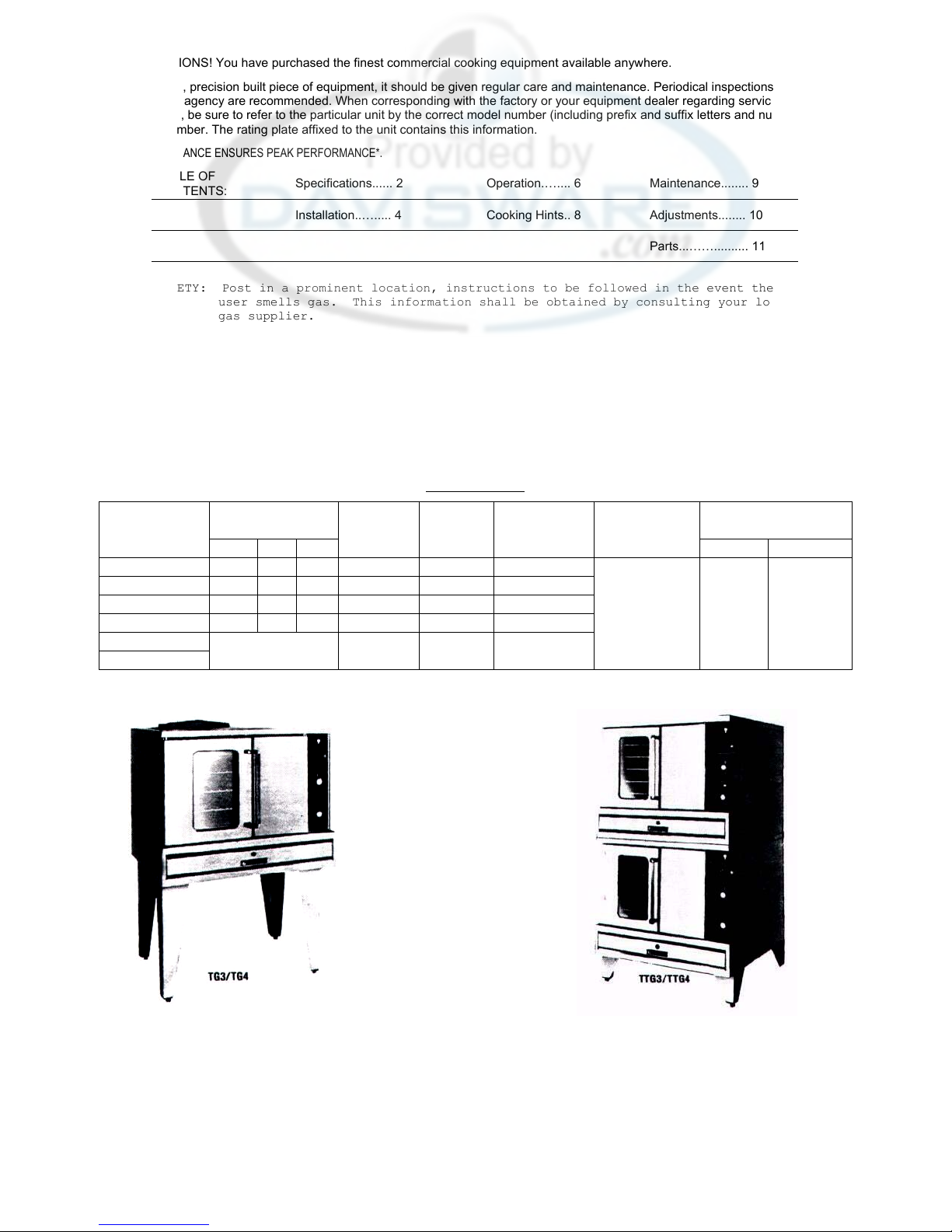
CONGRATULATIONS! You have purchased the finest commercial cooking equipment available anywhere.
Like any other fine, precision built piece of equipment, it should be given regular care and maintenance. Periodical inspections by your dealer or
a qualified service agency are recommended. When corresponding with the factory or your equipment dealer regarding service problems or
replacement parts, be sure to refer to the particular unit by the correct model number (including prefix and suffix letters and numbers) and the
serial or. code number. The rating plate affixed to the unit contains this information.
*REGULAR MAINTENANCE ENSURES PEAK PERFORMANCE*.
TABLE OF
CONTENTS:
Specifications...... 2
Installation..…..... 4
Operation.….... 6
Cooking Hints.. 8
Maintenance........ 9
Adjustments........ 10
Parts...…….......... 11
FOR YOUR SAFETY: Post in a prominent location, instructions to be followed in the event the
user smells gas. This information shall be obtained by consulting your local
gas supplier.
SPECIFICATIONS
DIMENSIONS NAT. GAS GAS
INPUT INLET
ELECT. CHAR GAS SUPPLY
@ 115 VAC. PRESSURE REQUIRED
MODEL NO. W D H BTU/HR N.P.T.. MOTOR SINHL"E PHASE NATURAL PROPANE
TG3 40" 36" 60" 80,000 (1) 3/4" (1) 3/4 HP
TG4 40" 42" 60" 80,000 (1) 3/4" (1) 3/4 HP 13.5 AMPS 7 "WC 11" WC
TTG3 40" 36" 72" 160,000 (1) 1" (2) 3/4 HP ea. Each
TTG4 40" 42" 72" 160,000 (1) 1" (2) 3/4 HP ea. Oven
All All
TG3-X/TG4-X See Appropriate 100,000 (1) 3/4 " (1) 3/4 HP Section Models Models
TTG3-X/TTG4-X Model Above 200,000 (1) 1" (2) 3/4 HP ea
NOTE: 6' LINE CORD SUPPLIED ON EACH OVEN SECTION.
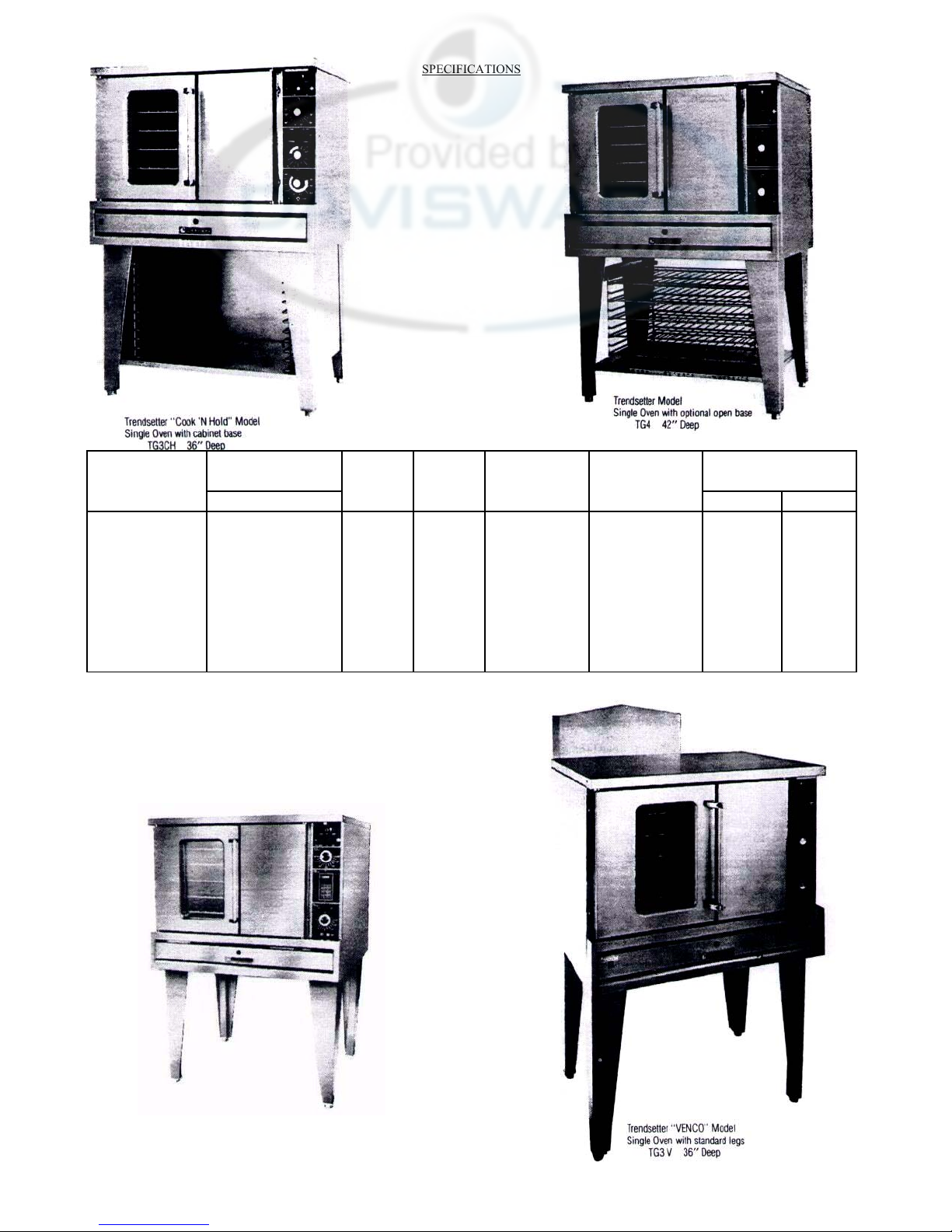
SPECIFICATIONS
MODEL NO. W D H 6TU/HR N.P.T. MOTOR SINGLE PHASE NATURAL PROPANE
TG3CH, TG3V,
TG3EC-CH
TG4CH, TG4V,
TG4EC-CH
TTG3CH, TTG3V,
TTG3EC-CH
TTG4CH, TTG4V,
TTG4EC-CH
DIMENSIONS INPUT INLET
40" 36" 60" 80, 000 (1) 3/4" (1) 3/4 HP
40" 42" 60" 80,000 (1) 3/4" (1) 3/4 HP 13.5 AMPS Each 7" WC 11" WC
40" 36" 72" 160,000 (1) 1" (2) 3/4 HP ea. Oven
40" 42" 72" 160,000 (1) 1" (2) 3/4 HP ea. Section
NAT. GAS GAS
ELECT. CHAR. GAS SUPPLY
@ 115 VAC. PRESSURE RFOIITRFD
All All
Models Models
COOK'N HOLD MODEL
ELECTRONIC CONTROL
INSTALLATION Before assembly and connection check gas supply.
A. The type of gas for which the unit is equipped is stamped on the data plate located behind lower front panel. Connect a
unit stamped "NAT" only to natural gas; connect those stamped "LP" only to propane gas.
B. If it is a new installation: have the gas authorities check meter size and piping to assure that the unit is supplied with
sufficient amount of gas pressure required to operate the UNIT.
C. If it is additional or replacement equipment: have gas authorities check pressure to make certain that existing meter and
piping will supply fuel at the unit with not more than 1/2" water column pressure drop.
NOTE: WHEN CHECKING PRESSURE BE SURE THAT ALL OTHER EQUIPMENT ON THE SAME GAS LINE IS ON. A
pressure regulator is supplied with GARLAND Convection Ovens. SET REGULATOR TO DELIVER GAS AT PRESSURE
SHOWN ON RATING PLATE.
Installation must conform with the National Fuel Gas Code ANSI-Z 223.1-1984 NFPA No. 54-1984 and/or local code to assure
safe and efficient operation.
The appliance and its individual shutoff valve must be disconnected from the gas supply piping system during any pressure
testing of that system at pressures in excess of 1/2 PSIG (3.45 KP2).
The appliance must be isolated from the gas supply piping system by closing its individual manual shutoff valve during any
pressure testing of the gas supply piping system at test pressures equal to or less than 1/2 PSIG (3.45 KP2).
NOTE: Adequate clearance must be provided for servicing and proper operation.
INSTALLATION FOR OVENS EQUIPPED WITH CASTERS
A. The installation shall be made with a connector that complies with the standard for connectors for movable gas appliances,
ANSI 221.69-1979.
B. The front casters of the unit are equipped with brakes to limit the movement of the oven without depending on the
connector and any quick-disconnect device or its associated piping to limit the appliance movement.
C. Please be aware, there is a restraint on the unit and if disconnection of the restraint is necessary, be sure to reconnect the
restraint after the oven has been returned to its originally installed position.
LEGS:
A. Position insert in bottom leg opening and tap insert up into leg till it seats at collar flange.
B. Raise oven. Do not lay unit on its back or sides. Place the front legs on the oven so as to line up with four attaching bolt
holes. Secure leg to oven frame using (4) 1/4 X 20 bolts and washers provided. Repeat at rear of unit.
C. Attach flue box over flue opening at the rear of unit with screws provided.
D. Maintain minimum wall clearance at the back and sides of the unit as noted on the unit rating plate.
E. Single and double deck ovens have a leveling adjustment at the bottom of each leg.
DOUBLE DECK UNITS.
A. Attach 8" legs to lower section. Follow same procedure as above for mounting legs.
B. Remove combustion chamber front of top deck (located under oven doors). Raise top deck into place and line up body sides
and back of the unit. Position mounting angle to line up with four attaching holes
located in center of the unit. Secure mounting angle with 4 metal screws provided.
Replace combustion chamber front. Fasten the rear of the 2 units together. with
mounting angle to "line up with four attaching holes located in the base of the top
deck and the lower deck flue box.
C. The flue for the TTG3/4 consist of three pieces. A lower flue box and an upper flue
box and a riser which connects the two flue boxes. Secure bottom ddtk flue box.
Attach flue riser to bottom flue box and secure. Attach top deck flue box.
D. Assemble stacking pipes according to illustration. Level unit four (4) ways and hook
up gas feed line. Plug in the cord set of each unit.
CLEARANCES: FROM COMBUSTIBLE MATERIAL 6" REAR AND 6" SIDES.
Each gas appliance shall be located with respect to building construction and other
equipment so as to permit access to the appliance. Such access and clearance may
be necessary for servicing and cleaning.
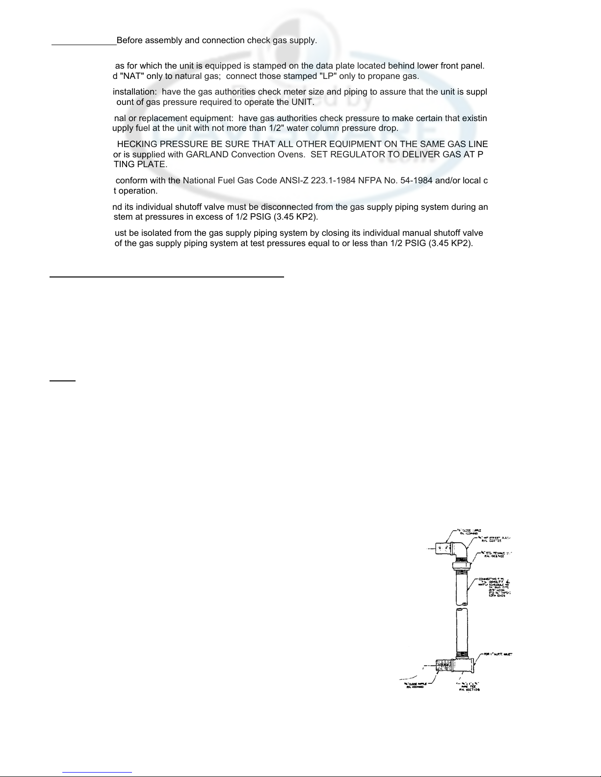
INSTALLATION GAS CONNECTIONS
The 1" NPT inlet of the tee must be considered in piping the gas supply for double stack units. Undersize gas supply 1ine(s)
may restrict the gas supply and affect performance. If other gas appliances are supplied by the same supply line, .the supply
line must be sized to carry the combined volume without causing more than 1/2" pressure drop at the Manifold of each appliance
on the line at full rate.
ELECTRICAL CONNECTIONS
A separate 15 AMP service must be provided for each oven section. For 115V usage, a cord and plug is provided but
connection to the electrical service must comply with local codes; or in the absence of local codes, with the National Electrical
Code, ANSI/NFPA No. 54-1984.
Each oven is electrically equipped with a cord set with a three prong plug which fits any standard 115V three prong grounded
receptacle.
wiring diagram is attached to the rear of the unit. WARNING:
ELECTRICAL GROUNDING INSTRUCTIONS
This appliance is equipped with a three-prong (grounding) plug for your protection against shock hazard and should
be plugged directly into a properly grounded three-prong receptacle. Do not cut or remove the grounding prong from
this plug.
VENTILATION AND AIR SUPPLY
Proper ventilation is highly important for good operation. The ideal method of ventilating a GAS Convection Oven is the use of a
properly designed canopy which should extend 6" beyond all sides of the appliance and 6'6" from the floor.
A strong exhaust fan will create a vacuum in the room, for an exhaust system vent to work properly, replacement air must enter
the room in which the vent is located. The amount of air which enters must equal the amount exhausted.
A11 gas burners and pilots need sufficient air to operate and large objects should not be placed in front of this oven which would
obstruct the air flow through the front.
If the unit is to be connected directly to a direct flue, it is recommended that a flue hood assembly and 8" draft diverter (for
double deck units) or a flue hood assembly and 6" draft diverter (for single units) be installed to insure proper ventilation. A11
parts described above are available from GARLAND.
NOTE: DO NOT DIRECT VENT THE V-SERIES. THIS UNIT SHOULD BE INSTALLED UNDER A POWER
VENT HOOD ONLY. DRAFT HOOD
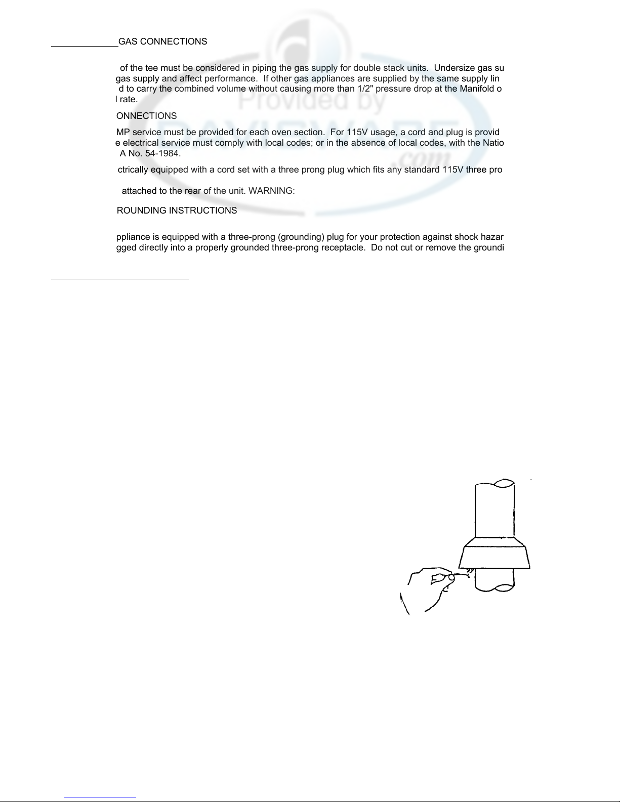
If your oven(s) are connected to a direct flue vent it will require periodical examination and cleaning. Commercial cooking
equipment requires an adequate ventilation system. For additional information refer to the National Fire Protection Association
Standard No. 96. If you experience pilot outage or erratic bake results you can
make an easy check on the direct flue system.
After the appliance has been on for approximately 15 minutes, strike a wooden
kitchen match. Blow it out and while still smoking hold it near the draft hood relief
opening (see sketch). If the smoke is not easily drawn into the opening the vent is
not functioning properly. Consult your vent installer or factory service agent for
further action.
NOTE: Each oven has been factory tested and adjusted prior to shipment. It may be
necessary to further adjust the oven as part of a proper installation. Such
adjustments are the responsibility of the installer Adjustments are not
considered defects in material and workmanship, and they are not covered
under the original equipment warranty.
TESTING AND LIGHTING INSTRUCTIONS
1. Turn on main gas valve. Leak test a11 fittings and connections ahead of the
service valve located upstream from the gas solenoid. (Open combustion chamber door to expose). Correct any leaks and
recheck.
2. Open service valve and gas will be flowing to the inlet side of the oven safety valve, including the inlet pilot fitting. Check all
fittings and pipe connections to the inlet side of the oven safety valve.
3. Depress and hold the red reset button located on the oven safety valve.
4. With a lighted taper, ignite pilot which is located to the right of the burner package about 9" inward from the manifold, air
should be purged from the line to achieve pilot ignition.
5. After the pilot is lit, leak test the rest of the system.
OPERATION OPERATION CHECK: ALL MODELS
1. When all gas connections have been checked out, proceed as follows to put the unit into operation.
A. Activate power switch located on top of control panel. Lamp will light indicating power on.
B. Activate fan switch.
C. Set thermostat to desired temperature. The burner indicator lamp will be on only while the thermostat is supplying gas
to the main burners, when the lamp is out, the oven temperature is at the temperature indicated by the thermostat dial.
2. COOL DOWN INSTRUCTIONS
A. Turn thermostat off.
B. Power switch must remain on.
3. SHUT DOWN INSTRUCTIONS
A. Turn a11 controls off.
B. Return a11 switches to the off position.
C. If the unit is to shut down for an extended period of time, dose the manual service valve located behind the combustion
chamber door.
STANDARD CONVECTION OVEN WITH COOK 'N HOLD OPTION.
PROCEDURE FOR CHECKING AS STANDARD CONVECTION OVEN
A. Activate "COOK" switch. Activate "HIGH" speed on two (2) speed fan switch.
B. Set low temperature with "COOK" thermostat.
C. Activate "TIMED" switch. Set timer at a low time setting.
D. Activate "BUZZER" switch. For shut down, reverse above steps.
PROCEDURE FOR CHECKING COOK 'N HOLD
A. Activate "COOK" switch. Activate "LOW" speed on two (2) speed fan switch.
B. Set desired cook temperature with "COOK" thermostat.
C. Activate "TIMED" switch. Activate "HOLD" switch.
D. Set "TIMER" at a low time setting.
E. Set "HOLD" thermostat for desired holding temperature. At the end of timed "COOK" cycle, unit
automatically switches to the hold control.
"PRODUCT READY" lamp will not illuminate until oven temperature coast down to the holding temperature. For shut
down, reverse above steps.
COOL DOWN INSTRUCTIONS
A. Return all switches and control to the "OFF" position. Open door.
B. Activate cool down switch and desired speed on fan switch. BUZZER AND TIMER
When using the timer, and buzzer, switch must be activated. Buzzer will sound when set time has passed. Buzzer
continues sounding until unit timer is manually moved to "OFF" or untimed position or buzzer switch returned to "OFF"
position.
OPERATION CHECK: V SERIES
1. Turn on main gas valve which is installed in main supply line.
2. V Series ovens are supplied with 2 gas valves. One is located upstream fro«J)the combination gas valve and one is
part of the combination gas valve. (Open combustion chamber door to expose both valves).
3. Open the gas shutoff valve upstream of the combination valve and leak test all joints and fittings.
 Loading...