

Page 1
INSTALLATION/OPERATION MANUAL
TRENDSETTER Gas Convection Oven
MODELS: TG3/4, TTG3/4
TG3/4-CH: TTG3/4-CH;
TG3/4-X: TTG3/4-X
TG3/4V; TTG3/4V;
TG3/4EC-CH; TTG3/4EC-CH
PLEASE READ ALL SECTIONS OF THIS MANUAL
THIS PRODUCT HAS BEEN CERTIFIED AS COMMERCIAL COOKING EQUIPMENT AND MUST BE INSTALLED
BY PROFESSIONAL PERSONNEL AS SPECIFIED.
WE SUGGEST INSTALLATION, MAINTENANCE AND REPAIRS SHOULD BE PERFORMED BY YOUR LOCAL
AUTHORIZED GARLAND SERVICE AGENCY LISTED IN YOUR INFORMATION MANUAL PAMPHLET.
In the event you have any questions concerning the installation, use, care or service of the product, write our
Customer Service Department.
NOTE: Unit must be installed with no less than 6" clearance from Combustible construction at rear and sides.
RETAIN FOR FUTURE REFERENCE.
Continuous product improvement is a Garland policy, therefore
specifications and design are subject to change without notice.
Garland Commercial Industries, Inc. Phone (717) 636-1000
Freeland, Pennsylvania 18224 Telex 887610
Printed in U.S.A.
Page 2
CONGRATULATIONS! You have purchased the finest commercial cooking equipment available anywhere.
Like any other fine, precision built piece of equipment, it should be given regular care and maintenance. Periodical inspections by your dealer or
a qualified service agency are recommended. When corresponding with the factory or your equipment dealer regarding service problems or
replacement parts, be sure to refer to the particular unit by the correct model number (including prefix and suffix letters and numbers) and the
serial or. code number. The rating plate affixed to the unit contains this information.
*REGULAR MAINTENANCE ENSURES PEAK PERFORMANCE*.
TABLE OF
CONTENTS:
Specifications...... 2
Installation..…..... 4
Operation.….... 6
Cooking Hints.. 8
Maintenance........ 9
Adjustments........ 10
Parts...…….......... 11
FOR YOUR SAFETY: Post in a prominent location, instructions to be followed in the event the
user smells gas. This information shall be obtained by consulting your local
gas supplier.
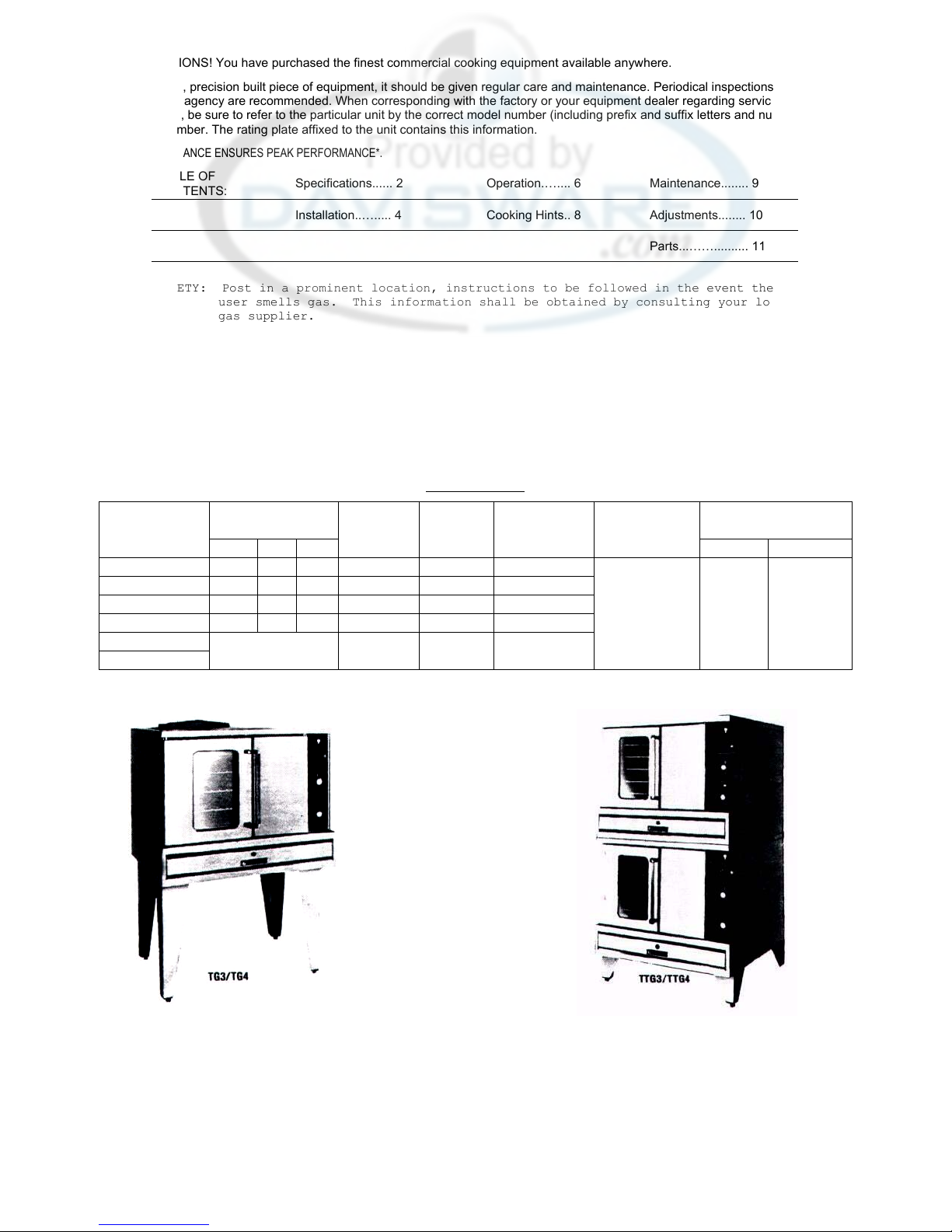
SPECIFICATIONS
DIMENSIONS NAT. GAS GAS
INPUT INLET
ELECT. CHAR GAS SUPPLY
@ 115 VAC. PRESSURE REQUIRED
MODEL NO. W D H BTU/HR N.P.T.. MOTOR SINHL"E PHASE NATURAL PROPANE
TG3 40" 36" 60" 80,000 (1) 3/4" (1) 3/4 HP
TG4 40" 42" 60" 80,000 (1) 3/4" (1) 3/4 HP 13.5 AMPS 7 "WC 11" WC
TTG3 40" 36" 72" 160,000 (1) 1" (2) 3/4 HP ea. Each
TTG4 40" 42" 72" 160,000 (1) 1" (2) 3/4 HP ea. Oven
All All
TG3-X/TG4-X See Appropriate 100,000 (1) 3/4 " (1) 3/4 HP Section Models Models
TTG3-X/TTG4-X Model Above 200,000 (1) 1" (2) 3/4 HP ea
NOTE: 6' LINE CORD SUPPLIED ON EACH OVEN SECTION.
Page 3
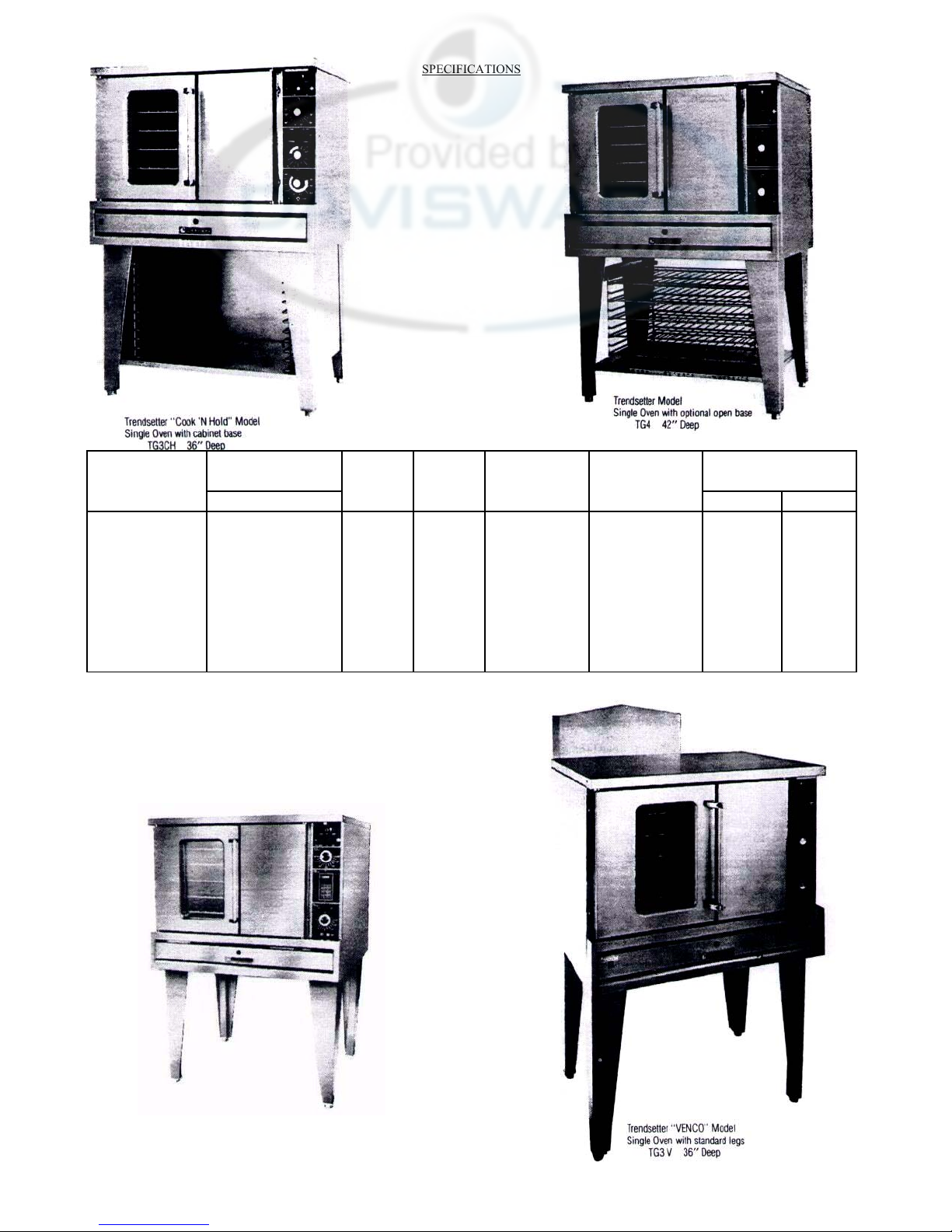
SPECIFICATIONS
MODEL NO. W D H 6TU/HR N.P.T. MOTOR SINGLE PHASE NATURAL PROPANE
TG3CH, TG3V,
TG3EC-CH
TG4CH, TG4V,
TG4EC-CH
TTG3CH, TTG3V,
TTG3EC-CH
TTG4CH, TTG4V,
TTG4EC-CH
DIMENSIONS INPUT INLET
40" 36" 60" 80, 000 (1) 3/4" (1) 3/4 HP
40" 42" 60" 80,000 (1) 3/4" (1) 3/4 HP 13.5 AMPS Each 7" WC 11" WC
40" 36" 72" 160,000 (1) 1" (2) 3/4 HP ea. Oven
40" 42" 72" 160,000 (1) 1" (2) 3/4 HP ea. Section
NAT. GAS GAS
ELECT. CHAR. GAS SUPPLY
@ 115 VAC. PRESSURE RFOIITRFD
All All
Models Models
COOK'N HOLD MODEL
ELECTRONIC CONTROL
Page 4
INSTALLATION Before assembly and connection check gas supply.
A. The type of gas for which the unit is equipped is stamped on the data plate located behind lower front panel. Connect a
unit stamped "NAT" only to natural gas; connect those stamped "LP" only to propane gas.
B. If it is a new installation: have the gas authorities check meter size and piping to assure that the unit is supplied with
sufficient amount of gas pressure required to operate the UNIT.
C. If it is additional or replacement equipment: have gas authorities check pressure to make certain that existing meter and
piping will supply fuel at the unit with not more than 1/2" water column pressure drop.
NOTE: WHEN CHECKING PRESSURE BE SURE THAT ALL OTHER EQUIPMENT ON THE SAME GAS LINE IS ON. A
pressure regulator is supplied with GARLAND Convection Ovens. SET REGULATOR TO DELIVER GAS AT PRESSURE
SHOWN ON RATING PLATE.
Installation must conform with the National Fuel Gas Code ANSI-Z 223.1-1984 NFPA No. 54-1984 and/or local code to assure
safe and efficient operation.
The appliance and its individual shutoff valve must be disconnected from the gas supply piping system during any pressure
testing of that system at pressures in excess of 1/2 PSIG (3.45 KP2).
The appliance must be isolated from the gas supply piping system by closing its individual manual shutoff valve during any
pressure testing of the gas supply piping system at test pressures equal to or less than 1/2 PSIG (3.45 KP2).
NOTE: Adequate clearance must be provided for servicing and proper operation.
INSTALLATION FOR OVENS EQUIPPED WITH CASTERS
A. The installation shall be made with a connector that complies with the standard for connectors for movable gas appliances,
ANSI 221.69-1979.
B. The front casters of the unit are equipped with brakes to limit the movement of the oven without depending on the
connector and any quick-disconnect device or its associated piping to limit the appliance movement.
C. Please be aware, there is a restraint on the unit and if disconnection of the restraint is necessary, be sure to reconnect the
restraint after the oven has been returned to its originally installed position.
LEGS:
A. Position insert in bottom leg opening and tap insert up into leg till it seats at collar flange.
B. Raise oven. Do not lay unit on its back or sides. Place the front legs on the oven so as to line up with four attaching bolt
holes. Secure leg to oven frame using (4) 1/4 X 20 bolts and washers provided. Repeat at rear of unit.
C. Attach flue box over flue opening at the rear of unit with screws provided.
D. Maintain minimum wall clearance at the back and sides of the unit as noted on the unit rating plate.
E. Single and double deck ovens have a leveling adjustment at the bottom of each leg.
DOUBLE DECK UNITS.
A. Attach 8" legs to lower section. Follow same procedure as above for mounting legs.
B. Remove combustion chamber front of top deck (located under oven doors). Raise top deck into place and line up body sides
and back of the unit. Position mounting angle to line up with four attaching holes
located in center of the unit. Secure mounting angle with 4 metal screws provided.
Replace combustion chamber front. Fasten the rear of the 2 units together. with
mounting angle to "line up with four attaching holes located in the base of the top
deck and the lower deck flue box.
C. The flue for the TTG3/4 consist of three pieces. A lower flue box and an upper flue
box and a riser which connects the two flue boxes. Secure bottom ddtk flue box.
Attach flue riser to bottom flue box and secure. Attach top deck flue box.
D. Assemble stacking pipes according to illustration. Level unit four (4) ways and hook
up gas feed line. Plug in the cord set of each unit.
CLEARANCES: FROM COMBUSTIBLE MATERIAL 6" REAR AND 6" SIDES.
Each gas appliance shall be located with respect to building construction and other
equipment so as to permit access to the appliance. Such access and clearance may
be necessary for servicing and cleaning.
Page 5
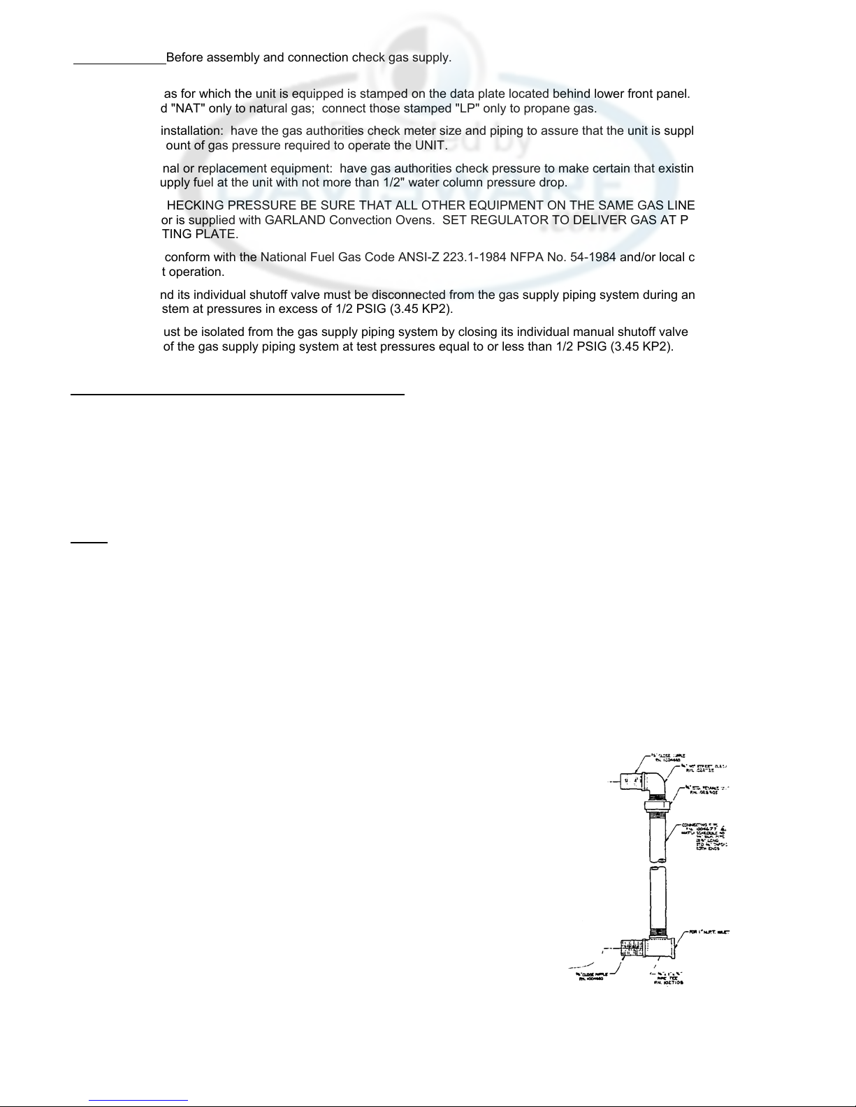
INSTALLATION GAS CONNECTIONS
The 1" NPT inlet of the tee must be considered in piping the gas supply for double stack units. Undersize gas supply 1ine(s)
may restrict the gas supply and affect performance. If other gas appliances are supplied by the same supply line, .the supply
line must be sized to carry the combined volume without causing more than 1/2" pressure drop at the Manifold of each appliance
on the line at full rate.
ELECTRICAL CONNECTIONS
A separate 15 AMP service must be provided for each oven section. For 115V usage, a cord and plug is provided but
connection to the electrical service must comply with local codes; or in the absence of local codes, with the National Electrical
Code, ANSI/NFPA No. 54-1984.
Each oven is electrically equipped with a cord set with a three prong plug which fits any standard 115V three prong grounded
receptacle.
wiring diagram is attached to the rear of the unit. WARNING:
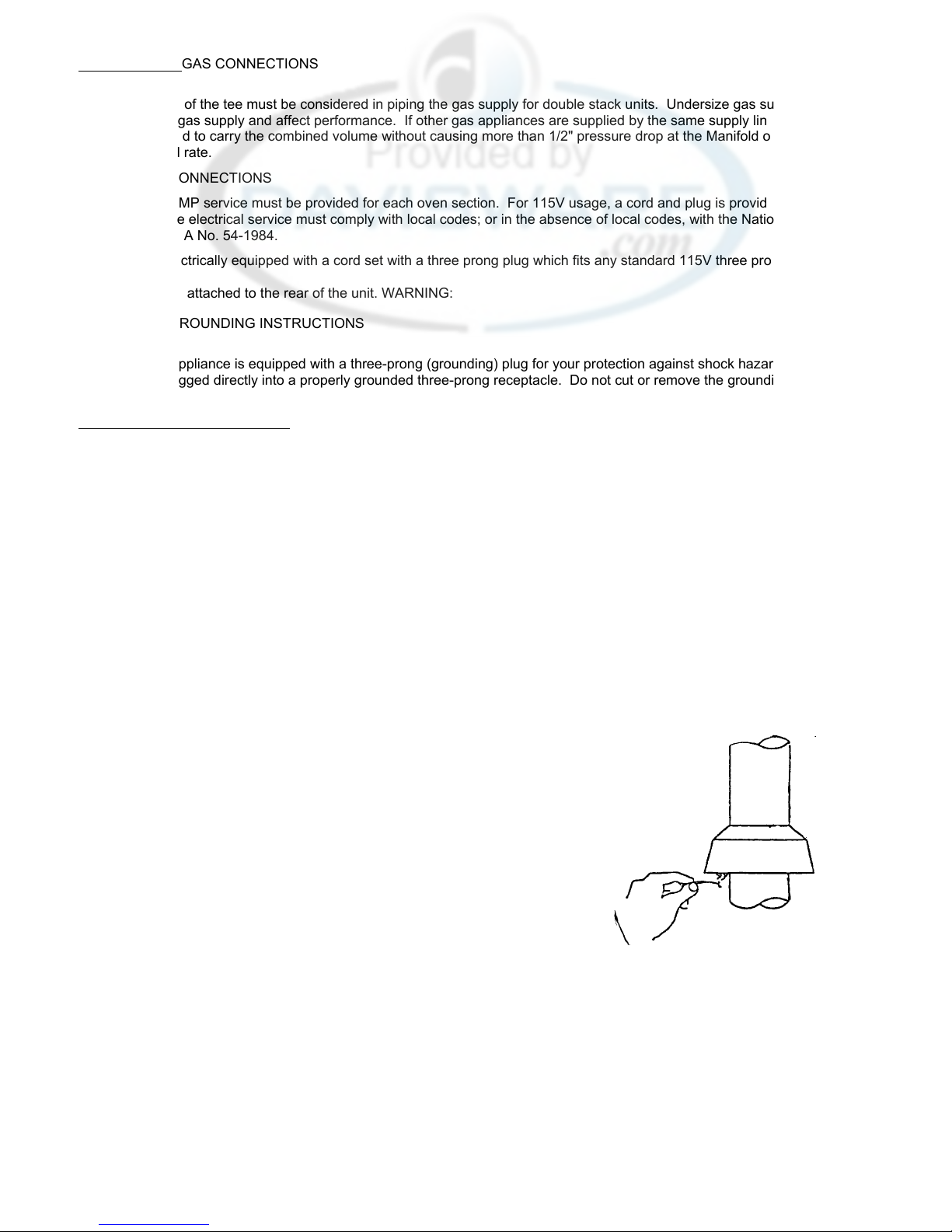
ELECTRICAL GROUNDING INSTRUCTIONS
This appliance is equipped with a three-prong (grounding) plug for your protection against shock hazard and should
be plugged directly into a properly grounded three-prong receptacle. Do not cut or remove the grounding prong from
this plug.
VENTILATION AND AIR SUPPLY
Proper ventilation is highly important for good operation. The ideal method of ventilating a GAS Convection Oven is the use of a
properly designed canopy which should extend 6" beyond all sides of the appliance and 6'6" from the floor.
A strong exhaust fan will create a vacuum in the room, for an exhaust system vent to work properly, replacement air must enter
the room in which the vent is located. The amount of air which enters must equal the amount exhausted.
A11 gas burners and pilots need sufficient air to operate and large objects should not be placed in front of this oven which would
obstruct the air flow through the front.
If the unit is to be connected directly to a direct flue, it is recommended that a flue hood assembly and 8" draft diverter (for
double deck units) or a flue hood assembly and 6" draft diverter (for single units) be installed to insure proper ventilation. A11
parts described above are available from GARLAND.
NOTE: DO NOT DIRECT VENT THE V-SERIES. THIS UNIT SHOULD BE INSTALLED UNDER A POWER
VENT HOOD ONLY. DRAFT HOOD
If your oven(s) are connected to a direct flue vent it will require periodical examination and cleaning. Commercial cooking
equipment requires an adequate ventilation system. For additional information refer to the National Fire Protection Association
Standard No. 96. If you experience pilot outage or erratic bake results you can
make an easy check on the direct flue system.
After the appliance has been on for approximately 15 minutes, strike a wooden
kitchen match. Blow it out and while still smoking hold it near the draft hood relief
opening (see sketch). If the smoke is not easily drawn into the opening the vent is
not functioning properly. Consult your vent installer or factory service agent for
further action.
NOTE: Each oven has been factory tested and adjusted prior to shipment. It may be
necessary to further adjust the oven as part of a proper installation. Such
adjustments are the responsibility of the installer Adjustments are not
considered defects in material and workmanship, and they are not covered
under the original equipment warranty.
TESTING AND LIGHTING INSTRUCTIONS
1. Turn on main gas valve. Leak test a11 fittings and connections ahead of the
service valve located upstream from the gas solenoid. (Open combustion chamber door to expose). Correct any leaks and
recheck.
2. Open service valve and gas will be flowing to the inlet side of the oven safety valve, including the inlet pilot fitting. Check all
fittings and pipe connections to the inlet side of the oven safety valve.
3. Depress and hold the red reset button located on the oven safety valve.
4. With a lighted taper, ignite pilot which is located to the right of the burner package about 9" inward from the manifold, air
should be purged from the line to achieve pilot ignition.
5. After the pilot is lit, leak test the rest of the system.
Page 6
OPERATION OPERATION CHECK: ALL MODELS
1. When all gas connections have been checked out, proceed as follows to put the unit into operation.
A. Activate power switch located on top of control panel. Lamp will light indicating power on.
B. Activate fan switch.
C. Set thermostat to desired temperature. The burner indicator lamp will be on only while the thermostat is supplying gas
to the main burners, when the lamp is out, the oven temperature is at the temperature indicated by the thermostat dial.
2. COOL DOWN INSTRUCTIONS
A. Turn thermostat off.
B. Power switch must remain on.
3. SHUT DOWN INSTRUCTIONS
A. Turn a11 controls off.
B. Return a11 switches to the off position.
C. If the unit is to shut down for an extended period of time, dose the manual service valve located behind the combustion
chamber door.
STANDARD CONVECTION OVEN WITH COOK 'N HOLD OPTION.
PROCEDURE FOR CHECKING AS STANDARD CONVECTION OVEN
A. Activate "COOK" switch. Activate "HIGH" speed on two (2) speed fan switch.
B. Set low temperature with "COOK" thermostat.
C. Activate "TIMED" switch. Set timer at a low time setting.
D. Activate "BUZZER" switch. For shut down, reverse above steps.
PROCEDURE FOR CHECKING COOK 'N HOLD
A. Activate "COOK" switch. Activate "LOW" speed on two (2) speed fan switch.
B. Set desired cook temperature with "COOK" thermostat.
C. Activate "TIMED" switch. Activate "HOLD" switch.
D. Set "TIMER" at a low time setting.
E. Set "HOLD" thermostat for desired holding temperature. At the end of timed "COOK" cycle, unit
automatically switches to the hold control.
"PRODUCT READY" lamp will not illuminate until oven temperature coast down to the holding temperature. For shut
down, reverse above steps.
COOL DOWN INSTRUCTIONS
A. Return all switches and control to the "OFF" position. Open door.
B. Activate cool down switch and desired speed on fan switch. BUZZER AND TIMER
When using the timer, and buzzer, switch must be activated. Buzzer will sound when set time has passed. Buzzer
continues sounding until unit timer is manually moved to "OFF" or untimed position or buzzer switch returned to "OFF"
position.
OPERATION CHECK: V SERIES
1. Turn on main gas valve which is installed in main supply line.
2. V Series ovens are supplied with 2 gas valves. One is located upstream fro«J)the combination gas valve and one is
part of the combination gas valve. (Open combustion chamber door to expose both valves).
3. Open the gas shutoff valve upstream of the combination valve and leak test all joints and fittings.
Page 7

LIGHTING INSTRUCTIONS: V Series
1. Activate power 'ON" switch.
2. Activate "COOK" switch.
3. Turn thermostat on full.
4. At this time the damper operator is energized and the damper will be fully open in 15 seconds.
5. Once the damper has opened fully, pilot valve and spark transformer are energized.
6. Spark will continue until pilot gas is present and pilot has lit.
7. Once the pilot flame has been established the main burner gas valve will open and ignition to the burners will take place.
NOTE: When the oven temperature reaches the dial setting, the ignition system is de-energized and the damper operator is
energized. Damper closes in 15 seconds.
NOTE: The V-Series is supplied with a redundant gas valve, with a built in pressure regulator. Therefore the unit is not
supplied with an external pressure regulator.
OPERATION CHECK COOK 'N HOLD EQUIPPED WITH ELECTRONIC CONTROL PANEL:
Procedure for using as standard convection oven.
A. A11 switches and controls in 'OFF" position. Timed/Untimed switch in "UNTIMED" position.
B. Activate "COOK" switch. Activate "HIGH" speed on fan switch.
C. Set desired temperature with "COOK" thermostat.
NOTE: "HEAT ON" pilot lamp will remain on until the preset temperature is reached. This lamp will cycle on and off with the
thermostat.
After preheat insert product. TIMER
OPERATION
FEATURES
1. Minute minder operation.
2. Timed cook operation.
3. Cook 'n Hold operation.
MINUTE MINDER OPERATION
A. Press clear pad on timer.
B. Enter time in hours and minutes by pressing appropriate keypads.
C. Press start pad.
Timer will count down as indicated by flashing lower colon in display. When display reaches 00:00 a beep tone will
sound for 30 seconds, to alert operator. Timer will then count up as indicated by flashing upper colon and will indicate
elapsed time on the display. Pressing clear pad win return timer to standby mode 00:00.
TIMED COOK OPERATION:
A. All switches and controls in "OFF" position timed/untimed switch in untimed position.
B. Activate "COOK" switch, activate "HIGH" speed on fan switch.
C. Set cook thermostat to desired temperature. When preset temperature is reached "HEAT ON" lamp wi11 go off. After
preheat - insert product.
D. Activate "TIMED" switch. Enter desired cooking time in hours and minutes.
E. Press start pad on timer. At the end of the cooking time, the oven will switch off and a beeping tone win sound for 30
seconds to alert operator. Timer will now count up to indicate elapsed time. Pressing "CLEAR" will return timer to
standby mode.
Page 8

OPERATION COOK 'N HOLD OPERATION
A. All switches and controls must be in 'OFF" position. Timer in standby mode (press clear pad).
B. Activate "COOK" switch. Activate "LOW" speed on fan switch. Set desired temperature with "COOK"
thermostat.
NOTE: Preheat until "HEAT ON" lamp goes off.
C. Activate "TIMED" switch. Activate "HOLD" switch set timer for desired cooking period.
D. Set hold thermostat for desired holding temperature.
E. Press start pad on timer. At end of cook cycle unit automatically switches to the hold control.
"PRODUCT READY" lamp wi11 illuminate after coast down to holding temperature. At this time product
may be removed or held in the hold mode. Timer Wi11 indicate elapsed time since end of cook cycle.
POWER FAILURE: In the event of a power failure, no attempt should be made to operate this oven.
TO CONSERVE ENERGY: Do not waste energy by leaving controls at high temperature settings during idle
IMPORTANT: All gas burners and pilots need sufficient air to operate and large objects should not be
FOR YOUR SAFETY: KEEP YOUR APPLIANCE AREA FREE FROM COMBUSTIBLES.
This unit is gas operated but also has electrical features, motor, thermostat and
solenoid.
periods. Lower settings will keep oven warm and ready for next use period. Reset
controls as required for heavy load period.
placed in front of this unit which would obstruct the air flow through the front.
Objects should not be placed on main top rear of unit white in use. This could obstruct
the venting system of the units flue products.
NOTE- THE SUGGESTED TIMES AND TEMPERATURES MAY VARY CONSIDERABLY FROM THOSE SHOWN ABOVE. THEY ARE
AFFECTED BY WEIGHT OF LOAD, TEMPERATURE OF THE PRODUCT, RECIPE, TYPE OF PAN AND CALIBRATION OF
THERMOSTATS, ETC.
Page 9

USE GUIDE HELPFUL SUGGESTIONS:
1. Preheat oven thoroughly before use. It is best to preheat 50° higher than the cooking temperature. Then turn thermostat
back to desired temperatures after oven is loaded. This win compensate for heat lost during loading procedure.
2. In loading, center pans on rack. Always load each shelf evenly, to allow for proper heat circulation around the sides.
3. When baking a variation of products, start with the product calling for the lowest temperature and work your way up.
4. If the edges of the product are done but the center is undone or if there is much color variation (some is normal) reduce
the thermostat setting 25° and continue reducing until desired results are achieved. High temperature will not speed up
cooking time. It wi11 cause uneven baking results.
NOTE: Moisture wi11 escape around the doors when baking products with heavy mositure content such as: chicken,
potatoes and etc. TO PREVENT EXCESSIVE PRESSURE BUILDUP INSIDE THE OVEN crack open the doors
throughout the baking cycle.
All units wi11 have a controllable vent. The vent control is located at the inner front top of the oven cavity. Movement to the
left wi11 close the vent and movement to the right wi11 open the vent. (Keep vent dosed during preheat).
The desired dryness or moistness of the finished product will dictate the setting of the vent.
MAINTENANCE OVEN INTERIOR - OPTIONAL CONTINUOUS CLEAN
A. "Break-in Period"
- When the oven is new, operate the oven for at least two hours at high heat, with the oven empty,
before any normal cooking operation. Continue preheating the oven for two hours prior to use during the first week or
two. During this break-in period, it is important that the oven surfaces be kept clean of any excessive soiling due to
spillage.
B. How to put "continuous cleaning" action to work - Each day, after baking and roasting operations have ceased, empty the
oven, turn the temperature control up to high heat. This high heat will accelerate the cleaning action and reduce the
time required to effectively clean the oven. Usually the cleaning operation wi11 take about 45 to 60 minutes.
C. Heavy Staining
- When the oven appears soiled, due to heavy staining, we suggest pre-heating the empty oven each
day for 1 or 2 hours (depending on the condition of the oven) for effective results. Also, ordinary household ammonia
has proven to be effective in removing baked-on "soil" build-up, and has the beneficial effect of keeping the microscopic
"pores" of the coating open and free to perform its cleaning action. An occasional light swabbing with household
ammonia while the oven is at room temperature wi11 prove extremely beneficial.
Abrasives should not be used
- In order to maintain continuous cleaning action, it is very important to avoid the use of
abrasive materials such as steel wool scouring pads, abrasives or sharp implements which can cause permanent
damage to the surface coating. In addition, oven cleaners such as Easy Off or Dow Oven Cleaners will clog the
"PORES" of the special coating and will retard the cleaning action.
D. Period "Tune-Up"
- Although the oven appears dean, we recommend operating the oven at high heat for 2 hours
approximately once each month. This wi11 insure against build-up of solids in hard to see places and in the pores of
the coating.
EXTERIOR FINISHES
Painted and stainless surface may be cleaned and kept in good condition by applying a light oil such as Shiela Shine.
Saturate a soft doth and wipe oven exterior when cold. Wipe excess with a dean doth.
OVEN INTERIOR
Before cleaning oven interior, remove oven racks and rack guides. Oven racks and rack guides can be cleaned with a
mild soap and warm water.
The porcelain interior can be easily cleaned with oven cleaners such as Easy-Off, or Dow Oven Cleaner. Apply only when
oven is cold.
MAINTENANCE - MOTOR CARE
The motor on your GARLAND convection oven is maintenance free since it is constructed with self-lubricating sealed ball
bearings. It is designed to provide durable service when treated with ordinary care. We have a few suggestions to follow on
the care of your motor. When the motor is operating, it cools itself internally by air entering at the rear of the motor case,
provided proper clearance has been allowed.
Page 10

Since the blower wheel is in the oven cavity it is at the same temperature as the oven. If the motor
is stopped while the oven is hot, the heat from the blower wheel is conducted down the shaft and into
the armature of the motor. This action could shorten motor life.
We recommend, at the end of the bake or roasting period, when the oven will be idle for any period of
time or before shutting down completely, that the doors be left open, and by use of the cool-down
position of the fan switch, the fan continues to run at least 5 minutes. The "FAN" should never be
turned "OFF" when the oven is "HOT".
ADJUSTMENTS CALIBRATION. COOK THERMOSTAT. AND COOK 'N HOLD THERMOSTAT
Field recalibration is seldom necessary and should not be resorted to unless experience with cooking
results definitely proves that the control is not maintaining the temperature to which the dial is set.
To check oven temperature when calibrating use only a reliable mercury thermometer or preferably an
oven pyrometer. To check calibration proceed as follows:
1. Place the weighted thermocouple of the test instrument or reliable mercury thermometer in the
center of the oven.
2. Activate cook or power switch and high fan switch.
3. Turn oven temperature control dial to 400°F. In order to allow the oven temperature to stabilize
the oven control must be allowed to cycle twice before taking a test reading.
4. Check temperature reading when control just cycles "OFF" and again when control just cycles
"ON" as indicated by the cycling pilot lamp above control.
5. If the AVERAGE of the two temperature readings do not read within 15° of the dial setting,
recalibrate as follows:
6. Carefully remove the thermostat dial, not disturbing dial setting.
7. Hold dial shaft steady and with a thin bladed screwdriver turn calibration screw, located inside
the dial shaft clockwise to decrease and counter-clockwise to increase the temperature, e.g.: 1/4
turn = 35°F
8. Replace thermostat dial and repeat step 3 through 5 to verify correct adjustment has
been made.
HOLD THERMOSTAT CALIBRATION ON OVENS WITH COOK 'N HOLD OPTION
Calibration check of the HOLD thermostat is very important.
1. Place the weighted thermocouple of the test instrument or reliable mercury thermometer in center
of oven. Calibration should be checked with dial setting at 150°F.
2. Activate cook or power switch; low fan switch, timed and hold switches.
3. Set "HOLD" thermostat at 150°F and set timer at hold position. Allow thermostat to cycle on and
off indicated by pilot lamp over control at least twice to allow oven temperature to stabilize.
4. Check temperature reading when control cycles 'OFF" and again when control cycles "ON" as
indicated by cycling pilot lamp.
5. If the average of the 2 temperature readings are not within plus or minus 10° of the dial
setting, recalibrate as follows:
6. Carefully remove the thermostat dial, not disturbing the dial setting.
7. Hold dial shaft steady and with a thin bladed screw-driver, turn calibration screw, located inside
the dial shaft, clockwise to decrease and counter-clockwise to increase the temperature, e/g/:
1/4 turn = 12°
8. Replace thermostat dial and repeat steps 3 through 5 to verify correct adjustment has been made.
Page 11

1. Remove combustion chamber front (located under oven doors). This win expose the door mechanism.
2. Close both doors.
3. Adjust both turnbuckles by "opening equally" so the mechanism and chains can be installed over the
sprockets.
4. Place the chains around the sprockets, so there are 8 regular links plus one master link on the
forward side of each chain.
5. Adjust the turnbuckles so the right door doses about 1/4 to 1/2 inch ahead of the left door. The
left turnbuckle adjust the right door and right turnbuckle adjust the left door.
6. Secure the turnbuckles by tightening lock nuts.
PARTS LIST
PART NO.
1003099
1003000
1003003
1003010
1021904
1021903
1304201
1304210
1304202
1304211
1029279
1011605
1010999
1120002
1016701
1016703
1016700
1016702
1013400
1013401
1297199
1019418
1269701
1269703
1330201
1028720
1028289
1269700
1028288
1021299
1021100
1014201
1014200
1015000
1012600
1012700
1315700
1315701
1317600
1029278
1301507
1019600
1301302
DESCRIPTION TG3
Motor Assembly - With Blower Wheel 1
Motor 3/4 HP 115V , 1
Motor 3/4 HP 115V - CH Models Only 1
Capacitor (Replacement on Motor)
Ooor Catch - Spring Type 1 3/4" Wide 1
Door Catch - Spring Type 1 3/4" Wide 1
Side Seal - Stainless Steel 2
Gasket Seal - Fiberglass 2
Top Seal Only - Bottom not required - Stainless Steel 1
Top and Bottom Seal Gasket Seat 2
Left Door Assembly (With Window) 1
Door Panel - Left Hand (With Window) 1
Oven Door Window 1
1/4 - 20 X 3" Alien Head Screw 2
Oven Door Handle End - Bottom 1
Oven Handle Spacer 2
Oven Door Handle 1
Oven Door Handle End - Top 1
Fireplate 1
Fireplate - Deep Fireplate Support 2
Thermocouple 18" 1
Pilot Sensing Probe Y75 (Venco Only) 1
Pilot Sencing Probe Y75 (Venco Only) 1
Ceramic Rod (Venco Only) 1
1/4" Tubing (TS11 to Pilot) 1
Pilot Assembly - Natural 1
Pilot Burner (Venco Only) 1
Pilot Assembly - Propane 1
Connecting Link Assembly 4
Roller Chain No. 40 2
Left Door Rod - Long 2
Right Door Rod - Short 2
Turnbuckle 2
Oven Rack Assembly 5
Oven Rack Assembly - Deep Rack Guide Assembly Right or Left Hand 2
Rack Guide Assembly Right or Left Hand - Deep Clip Rack Guide - New Style 6
Right Door Assembly Complete 1
Micro Switch Bracket 1
Micro Switch 1
Micro Switch Activator Assembly 1
TG4
1
1
1
1
1
2
2
1
2
1
1
1
2
1
2
1
1
1
2
1
1
1
1
1
1
1
1
4
2
2
2
2
5
2
6
1
1
1
1
Page 12

PART NO.
1027300
1027001
1019010
1019011
1032400
1230601
1314001
1314121
1285700
1285600
1019203
1019209
1019207
1019209
1019209
1019204
1019207
1019209
1006489
1006496
1006490
1270000
1181000
1252400
1244501
1244600
1252100
1265548
1265556
1265544
1265555
1302700
1302701
1269600
1269601
1369800
1302400
1270299
DESCRIPTION TG3
Solenoid Valve (120V Coi"1)± 1
TS11J Safety Valve 1
Regulator (Natural) 1
Regulator (Propane) 1
Oven Thermostat - 200°P to 500°F 1
Oven Thermostat - 100°F to 250°F (For CH Models Only) 1
Dial 2
Dial Insert 2
60 Minute Timer (115V, 50/60 HZ) 1
12 Hour Timer - CH Models Only (115V , 50/60 HZ) 1
Power (On-Off S.P.S.T.) 1
Fan - Cook/Cool Down (On-On D.P.D.T.) 1
Cook/Cool Down (On-Off-On D.P.D.T.) 1
Hi/Lo Fan (On-On D.P.D.T.) 1
Timer/Untuned (On-On D.P.D.T.) 1
Buzzer/Hold (On-Off-On S.P.D.T.) 1
Cook/Cool Down (On-Off-On D.'B.D.T.) 1
Hi/Lo Fan (On-On D.P.D.T.) 1
Pilot Lamp Assembly - Green 1
Pilot Lamp Assembly - Amber 1
Pilot Lamp Assembly - White - CH Models Only 1
Amber Pilot Lamp (Venco Only) 1
Momentary Push Button - Switch 1
Relay Mounting Spring - CH Models Only 1
Relay (120V Coil) - CH Models Only 1
Relay Socket - CH Models Only 1
Capacitor - CH Models Only 1
Burner Orifice #48 DMS - Natural 5
Burner Orifice #56 DMS - Propane 5
Burner Orifice M DMS - Natural - X Model 5
Burner Orifice #55 DMS - Propane - X Models 5
Vent Damper 1
Damper Cable 1
Spark Ignition Control Natural 1
Spark Ignition Control LP 1
Transformer 24V 1
Redundant Combination Gas Valve Natural 1
Propane Conversion Kit 1
PARTS LIST (CONTINUED)
ROCKER SWITCH TG MODELS
COOK 'N HOLD MODELS
TG MODELS WITH 2 SPEED MOTOR
VENCO
TG4
1
1
1
1
1
1
2
2
1
1
1
1
1
1
1
1
1
1
1
1
1
1
1
1
1
1
1
5
5
5
5
1
1
1
1
1
1
1
Page 13

Page 14

Page 15

Page 16

Page 17

 Loading...