

Page 1
INSTALLATION AND
OPERATION MANUAL
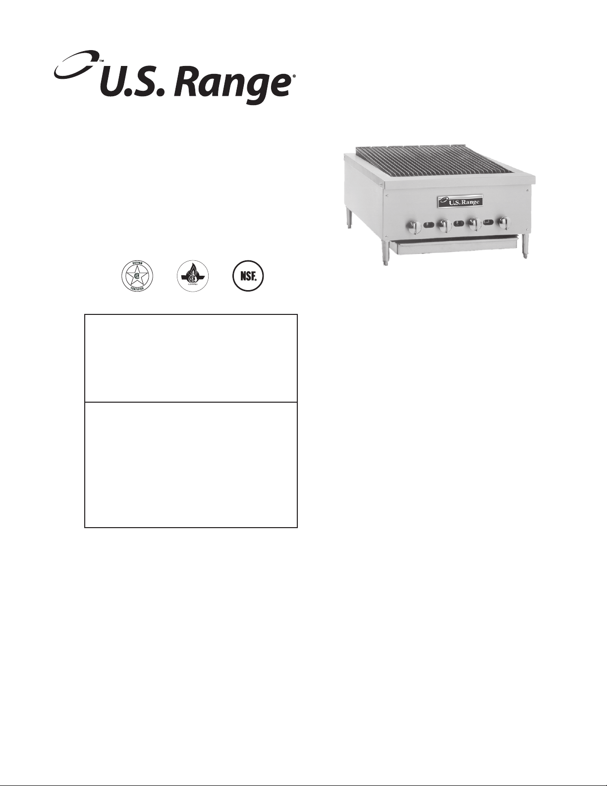
“REGAL” SERIES RADIANT
CHAR-BROILERS, (RBA)
FOR YOUR SAFETY:
DO NOT STORE OR USE GASOLINE
OR OTHER FLAMMABLE VAPORS OR
LIQUIDS IN THE VICINITY OF
THIS OR ANY OTHER
APPLIANCE
WARNING:
IMPROPER INSTALLATION, ADJUSTMENT,
ALTERATION, SERVICE OR MAINTENANCE
CAN CAUSE PROPERTY DAMAGE, INJURY,
OR DEATH. READ THE INSTALLATION,
OPERATING AND MAINTENANCE
INSTRUCTIONS THOROUGHLY
BEFORE INSTALLING OR
SERVICING THIS EQUIPMENT
AND RETAIN FOR FUTURE REFERENCE.
THIS PRODUCT HAS BEEN CERTIFIED AS
COMMERCIAL COOKING EQUIPMENT AND
MUST BE INSTALLED BY PROFESSIONAL
PERSONNEL AS SPECIFIED.
IN THE COMMONWEALTH OF MASSACHUSETTS
THIS PRODUCT MUST BE INSTALLED BY A
LICENSED PLUMBER OR GAS FITTER. APPROVAL
NUMBER: G-1-07-05-28
For Your Safety:
Post in a prominent location, instructions to be
followed in the event the user smells gas. This
information shall be obtained by consulting
your local gas supplier.
Users are cautioned that maintenance and repairs must be performed by a Garland authorized service agent
using genuine Garland replacement parts. Garland will have no obligation with respect to any product that has been
improperly installed, adjusted, operated or not maintained in accordance with national and local codes or installation
instructions provided with the product, or any product that has its serial number defaced, obliterated or removed,
or which has been modified or repaired using unauthorized parts or by unauthorized service agents.
For a list of authorized service agents, please refer to the Garland web site at http://www.garland-group.com.
The information contained herein, (including design and parts specifications), may be superseded and is subject
to change without notice.
PLEASE READ ALL SECTIONS OF THIS MANUAL
GARLAND COMMERCIAL INDUSTRIES
185 East South Street
Freeland, Pennsylvania 18224
Phone: (570) 636-1000
Fax: (570) 636-3903
Part # 1382692 Rev 3 (02/22/08) © 2005 Garland Commercial Industries, Inc.
Part # 1382692 Rev 3 (02/22/08) Page 1
GARLAND COMMERCIAL RANGES, LTD.
1177 Kamato Road, Mississauga, Ontario L4W 1X4
CANADA
Phone: 905-624-0260
Fax: 905-624-5669
Enodis UK LTD.
Swallow eld Way, Hayes, Middlesex UB3 1DQ ENGLAND
Telephone: 081-561-0433
Fax: 081-848-0041
Page 2

IMPORTANT INFORMATION
WARNING:
This product contains chemicals known to the state of California to cause cancer and/or birth defects
or other reproductive harm. Installation and servicing of this product could expose you to airborne
particles of glass wool/ceramic fibers. Inhalation of airborne particles of glass wool/ceramic fibers
is known to the state of California to cause cancer. Operation of this product could expose you to
carbon monoxide if not adjusted properly. Inhalation of carbon monoxide is known to the state of
California to cause birth defects or other reproductive harm.
Keep appliance area free and clear of combustibles.
Part # 1382692 Rev 3 (02/22/08)Page 2
Page 3

Part # 1382692 Rev 3 (02/22/08) Page 3
TABLE OF CONTENTS
IMPORTANT INFORMATION..........................................2
INTRODUCTION.....................................................4
Uncrating........................................................................4
Rating Plate......................................................................4
INSTALLATION......................................................4
Clearances.......................................................................4
Positioning and Setup............................................................4
Air Supply and Ventilation........................................................4
Standards .......................................................................5
Gas Supply ......................................................................5
Statutory Regulations ............................................................5
Manual Shut-O Valve...........................................................5
Pressure Regulator...............................................................5
Rigid Connections ...............................................................6
Flexible Couplings & Connectors..................................................6
Manual Pilot Valve...............................................................6
Testing and Adjustments.........................................................6
INITIAL OPERATION.................................................7
Initial Pilot Light .................................................................7
Final Preparation.................................................................7
CLEANING AND MAINTENANCE......................................7
General Cleaning ................................................................7
Daily ............................................................................7
Weekly..........................................................................8
Periodic.........................................................................8
Cleaning Stainless Steel ..........................................................8
SERVICE AND PARTS ................................................8
Page 4

INTRODUCTION
U.S. Range manufactures the “Regal” Char-Broiler (RBA) in
widths from two to six feet, to be used either as freestanding
counter units or built into either a “Cuisine” or “Performer”
range. All broilers are shipped completely assembled, with
the double drip pans and pressure regulator packed on
top of the broiler. A piece of 2x4 lumber is strapped to the
radiants to prevent vibration damage. All units are inspected
at the factory before shipping.
Uncrating
After uncrating, immediately check the equipment for visible
signs of shipping damage.
If such damage has occurred, do not refuse shipment, but
contact the shipper and le the appropriate freight claims.
INSTALLATION
Rating Plate
The rating plate is attached to the right side of the appliance.
When corresponding with the factory or your local
authorized factory service center regarding service problems
or replacement parts, be sure to refer to the particular unit
by the correct model number (including the prex and sux
letters and numbers) and the warranty serial number. The
rating plate axed to the unit contains this information.
Other information on this plate is the BTU/hr input to the
burners, outlet gas pressure in inches WC, and whether
oriced for natural or propane gas.
WARNING All U.S. Range char-broilers must be connected
only to the type of gas identied on the rating plate!
Clearances
The appliance area must be kept free and clear of all
combustibles. This unit is design-certied for the following
installations:
1. For installation in non-combustible locations only.
2. For use only with four-inch high adjustable legs.
3. Zero clearance is required from non-combustible
construction at sides and rear.
Adequate clearances must be maintained at all times in front
and at the sides of the appliance for servicing and proper
operation.
Positioning and Setup
Place a carpenter’s spirit level left-to-right on the front
landing ledge and across the back trim, and also front-toback on the right and left end trims. Level to the high corner
with the screw adjustment built into the foot of each leg.
Air Supply and Ventilation
The area around the appliance must be kept clear to avoid
any obstruction to the ow of combustion and ventilation
air, as well as, for ease of maintenance, service and proper
appliance operation. Keep proper clearances for adequate air
supply.
Means must be provided for any commercial, heavy-duty
cooking appliance to exhaust combustion waste products
to the outside of the building. This is doubly important
for open-grate broilers, since the design promotes grease
dripping through the grate onto the hot radiants, sending
smoke back up through the product as avor enhancement.
“Regal” series char-broilers must be installed under a
vent hood. Filters and drip troughs should be part of any
industrial hood, but consult local codes before construction
and installation.
Air movement should be checked during installation. Strong
exhaust fans in the hood or in the overall air conditioning
system can produce a slight vacuum in the room and/or
cause air drafts. These can interfere with pilot or burner
performance and can be hard to diagnose. If pilot or burner
outage problems persist, make-up air openings or baes
may have to be provided in the room. If pilot/burner outage
problems persist make-up air openings or baes may have
to be provided in the room.
Part # 1382692 Rev 3 (02/22/08)Page 4
Page 5

Part # 1382692 Rev 3 (02/22/08) Page 5
INSTALLATION Continued
Standards
Installation must be planned in accordance with all
applicable state and local codes, taking into account the
following standards (or latest edition):
Grease Extractor ANSI/NFPA 96-1992
Power Ventilators ANSI/NFPA 96-1987
Filter Unit ANSI/NFPA 96-1987
Smoke Detectors ANSI/NFPA 728-1986. CAN/ULC 85531986
Fire Extinguisher (C02) ANSI/NFPA 12-1989
This section is not intended to be complete and other
nationally recognized standards may be appropriate.
Gas Supply
1. Installation of the equipment should be made by a
licensed plumber.
2. A gas shut-o valve must be installed in the gas supply
line ahead or the appliance for safety and for ease of
future service.
2. The appliance must be isolated from the gas supply
piping system by closing its individual manual shuto
valve during any pressure testing of the gas supply piping
system at test pressures equal to or less than 1/2 psi (3.45
kPa)
Manual Shut-O Valve
This installer-supplied valve must be installed in the gas
service line ahead of the appliance and regulator in the gas
stream and in a position where it can be reached quickly in
the event of an emergency.
Pressure Regulator
All commercial cooking equipment must have a pressure
regulator on the incoming service line for safe and ecient
operation. The pressure regulator installed must be listed by
a nationally recognized agency. Line service pressure may
uctuate with local demand.
All “Regal” char-broilers must be installed with the included
gas pressure regulator.
Regulators are adjusted at the factory for 5” WC (natural gas)
or 10” WC (LP gas) depending on the customer’s ordering
instructions.
3. A gas pressure regulator must be installed at the
appliance prior to connecting the equipment to the gas
line. Failure to install a regulator will void the equipment
warranty.
NOTE: The gas supply (service) line must be the same size or
greater than the inlet line of the appliance. U.S. Range “Regal”
char-broilers use a 3/4” NPT inlet. Sealant on all pipe joints
must be resistive to LP gas.
To convert to propane or natural gas, contact a certied
service agency.
Statutory Regulations
Safe and satisfactory operation of your equipment depends,
to a great extent, on its proper installation. Installation must
conform to local codes or, in the absence of local codes with
the National Fuel code, ANSI Z223.1, Natural Gas Installation
Code, CAN/CGA-B149.1, or the Propane Installation Code,
CAN/CGA-B149.2, as applicable, including:
1. The appliance and its individual shuto valve must be
disconnected from the gas supply piping system during
any pressure testing of that system at test pressures in
excess of 1/2 psi (3.45 kPa).
Prior to connecting the regulator, check the incoming line
pressure, as these regulators can withstand a maximum
pressure of 1/2 psi (14” WC). If the Line pressure is beyond
this limit, a step-down regulator will be required. Doublecheck the arrow forged onto the bottom of the regulator
body which shows gas ow directions; it should point
downstream to the appliance. The red air-vent cap is part of
the regulator and should not be removed unless local codes
require external venting.
Regulators can be adjusted in the eld, but it is
recommended that they not be tampered with unless that
part is known to be out of adjustment or serious pressure
uctuations are found to exist and can be solved no other
way. Any adjustments to regulators must be made by
qualied service personnel with proper test equipment.
If a vent line from the gas appliance pressure regulator is
used, it should be installed to the outdoors in accordance
with local codes or code ANSI Z223.1, Natural Gas Installation
code, CAN/CGA-B149.1, or The Propane Installation code,
CAN/CGA-B149.2.
Page 6

INSTALLATION Continued
WARNING Failure to install a pressure regulator will void
the equipment warranty!
Rigid Connections
Double-check any installer-supplied intake pipes visually
and clear any dirt particles, threading chips, or other foreign
matter before installing in a service line. Those particles will
clog orices when gas pressure is applied.
WARNING All connections must be sealed with a joint
compound suitable for LP gas, and all connections must be
tested with a soapy solution before lighting any pilots!
Flexible Couplings & Connectors.
If the unit is to be installed with exible couplings and/or
quick disconnect ttings, the installer must use an AGA
design-certied commercial exible connector or at least
3/4” NPT (with suitable strain relief’s) in compliance with
the Standard for Connectors for Movable Gas Appliances,
ANSI Z21.69 /CSA 6.16, and a quick-disconnect device that
complies with the Standard for Quick-Disconnect Devices
for Use With Gas Fuel, ANSI Z21.41 / CSA 6.9. Domestic
connectors are not suitable!
Manual Pilot Valve
All burners are equipped with constant-burning pilots.
These should be manually lighted immediately after the
gas is turned on and the system is checked for leaks. Pilots
can be reached with a long match or taper down from the
top if the grates and radiants have not yet been installed, or
through the observation/adjustment openings in the valve
cover between the burner valve knobs. These openings also
contain the pilot valves, which are screwdriver adjustable.
Testing and Adjustments
Check all gas connections for leaks using a soapy solution
before lighting any pilots. DO NOT USE OPEN FLAME
TO CHECK FOR LEAKS! Putting open ame beside a new
connection is not only dangerous, but will often miss small
leaks that a soapy solution would nd.
All U.S. Range appliances are adjusted and tested before
leaving the factory, eectively matching them to sea
level conditions. Adjustments and calibrations to assure
proper operation may be necessary on installation to meet
local conditions, low gas pressure, dierences in altitude;
variations in gas characteristics, to correct possible problems
caused by rough handling or vibration during shipment, and
are to be performed only by qualied service personnel.
These adjustments are the responsibility of the customer,
installer and/or dealer and are not covered by the U.S. Range
warranty.
Part # 1382692 Rev 3 (02/22/08)Page 6
Page 7

Part # 1382692 Rev 3 (02/22/08) Page 7
INITIAL OPERATION
Initial Pilot Light
WARNING Keep appliances free and clear from combustibles
at all times. When lighting pilots and checking for burner
performance, do not keep your face close to the burners. The
burner may light with a “pop” and could ash back and cause
facial burns.
Before lighting any pilots, make sure that the burner valves
and thermostats are turned “OFF”.
Initial pilot light is in the following sequence:
1. Turn the manual shut-o valve on the incoming service
line “OFF”.
2. Turn all burner valves “OFF”.
3. Close all pilot adjusting screws (clockwise turn all the
way in).
4. Wait for any accumulated gas to disperse.
5. Open the manual shut-o valve.
6. Apply a lighted match or taper to a pilot burner and open
that pilot’s adjustment screw gradually until the pilot
lights.
7. Adjust the pilot ame for the desired characteristics.
8. Turn “ON” that main burner and watch to make sure it
lights from the pilot, then turn the burner “OFF”.
9. Repeat steps 6 through 8 to light all remaining pilots.
If only one pilot has gone out, it is not necessary to follow
the entire procedure outlined above. Merely apply a lighted
match or taper to the pilot until it lights, then adjust the pilot
valve. If the pilot will not light, close the adjustment valve
completely, do not use that burner, and call for service.
NOTE: It may be necessary to re-light the pilots several
times until the new lines are purged of any trapped air and
constant gas ow is attained.
Final Preparation
New units are wiped clean with solvents at the factory
to remove any visible signs of dirt, oil, grease, bacteria,
remaining from the manufacturing process.
They should be washed thoroughly with hot, soapy water
to remove lm residues and any installation dust or debris
before being used for food preparation. The top grates
should be removed and washed before use.
CLEANING AND MAINTENANCE
WARNING If gas odors are detected, the gas supply must
be turned “OFF’ at the main shut-o valve and the local
gas company or authorized service agency contacted for
service.
General Cleaning
Any piece of equipment works better and lasts longer when
maintained properly and kept clean. Cooking equipment is
no exception. Your U.S. Range “Regal” Char-Broiler must be
kept clean during the working day and thoroughly cleaned
at the end of each day.
Daily
1. Remove the broiler grates. Wire brush them clean or
any encrusted materials and wash in hot, soapy water. A
common cleaning practice is to turn grates up side-down
to burn o encrusted material. Do not do this with the
“Regal”Char-Broiler! The ame from the burner is shielded
by a cast iron radiant with the result that heat not ame
reaches the grate. It is likely that cooked-on matter will
cook in even deeper rather than burn o.
2. Remove the radiants and wire brush them clean, then
wash in hot soapy water. A rule of thumb is that if the
grates are becoming encrusted, so are the radiants.
Page 8

CLEANING AND MAINTENANCE Continued
3. The “Regal” Char-Broiler uses a double drip tray. The front
grease trough (at the top of the unit) downspouts to a 35/8” tray running the width of the body; remaining grease
which drips past the radiants is collected by a second
pan covering the remainder of the broiler bottom. The
front tray must be checked frequently during operation
and drained as necessary; the rear drip pan should also
be checked occasionally. Spills should be wiped as they
occur and, at the end of the day, both pans should be
washed in hot, soapy water.
Weekly
If a daily maintenance is performed as recommended above,
weekly maintenance will not be required beyond the daily
cleaning for the last day of the working week.
Periodic
Your U.S. Range “Regal” Char-Broiler should be checked and
adjusted periodically by qualied service personnel as part of
a regular kitchen maintenance program.
Cleaning Stainless Steel
1. During the day, all stainless steel body parts should be
wiped regularly with hot, soapy water. At the end of each
day, a liquid cleaner designed for this material should be
used.
2. Do not use steel wool, abrasive cloths, cleansers, or
powders. If it is necessary to scrape stainless steel to
remove encrusted material, soak the area with hot cloths
to loosen the material, then use a wood or nylon scraper.
3. Do not use a metal knife, spatula, or any other metal tool
to scrape stainless steel! Scratches are almost impossible
to remove.
SERVICE AND PARTS
Installation, maintenance and repairs should be performed
by your local authorized U.S. Range service agency listed in
your information manual pamphlet.
Part # 1382692 Rev 3 (02/22/08)Page 8
Page 9

Part # 1382692 Rev 3 (02/22/08) Page 9
Page 10

Page 11

Page 12

Pièce nº 1382692 Rev 3 (02/22/08) Page 9
dont le nom gure dans le manuel d’informations.
e ectués par l’agence de service U.S. Range locale autorisée
L’installation, l’entretien et les réparations devront être
SERVICE ET PIÈCES
Page 13

Pièce nº 1382692 Rev 3 (02/22/08)Page 8
chaude.
lèchefrites devront être nettoyés à l’eau savonneuse
dès qu’ils se produisent et, à la n de la journée les deux
lèchefrite arrière. Les débordements devront être essuyés
vider au besoin. Véri ez également de temps en temps la
lèchefrite avant pendant l’utilisation de l’appareil et de la
du grilloir. Il est nécessaire de véri er fréquemment la
dans une seconde lèchefrite qui recouvre le reste du fond
Le reste de la graisse s’égouttant des radiants est collecté
de 3 5/8 po faisant toute la largeur de la partie carrelée.
le dessus de l’unité carrelée) se vide dans une lèchefrite
d’une double lèchefrite. Le collecteur à graisse avant (sur
pratiquement impossibles à enlever.
- pour racler l’acier inoxydable. Les rayures sont
3. N’utilisez pas d’outils métalliques - couteau, spatule
Nylon.
les matières et utilisez ensuite une raclette en bois ou en
zone a ectée avec des torchons chauds pour décoller
pour nettoyer des matières incrustées, détrempez la
est nécessaire de gratter la surface en acier inoxydable
poudres de nettoyage ou autres produits abrasifs. S’il
2. N’utilisez pas de laine d’acier, de chi ons abrasifs, de
recommandé pour ce type de matériau.
de travail, utilisez un produit de nettoyage liquide
humide d’eau savonneuse chaude. A la n de la journée
essuyées pendant la journée de travail avec un chi on
1. Les parties de l’appareil en acier inoxydable devront être
3. Les grilloirs de type à charbon de bois « Regal » sont munis
de même des radiants.
D’une manière générale, si les grilles sont sales, il en est
métallique, avant de les laver à l’eau savonneuse chaude.
2. Retirez les radiants et nettoyez-les avec une brosse
d’avantage plutôt que de se décoller.
la grille. Il est probable que les aliments vont s’incruster
fait que c’est la chaleur et non pas la amme qui atteint
du brûleur est protégée par un radiant en fonte, ce qui
grilloir de type à charbon de bois « Regal ». La amme
brûler les résidus accumulés. Ne le faites pas avec votre
nettoie parfois les grilles en les retournant et en faisant
incrustés et lavez les dans l’eau savonneuse chaude. On
à l’aide d’une brosse métallique pour éliminer les résidus
1. Enlevez les grilles du grilloir. Brossez et nettoyez les grilles
Nettoyage De L’acier Inoxydable
cuisine.
dans le cadre du programme régulier d’entretien de la
réglé périodiquement par du personnel d’entretien quali é
Les grilloirs de type à charbon à bois « Regal » être véri é et
Périodiquement
dernière journée de travail de la semaine.
à l’entretien hebdomadaire autre que l’entretien normal de la
recommandé ci-dessus, il ne sera pas nécessaire de procéder
Si l’entretien quotidien est bien e ectué comme
Chaque Semaine
Chaque Jour
à fond à la n de la journée.
maintenu propre durant la journée de travail et être nettoyé
Votre grilloir de type à charbon de bois « Regal » doit être
équipements de cuisine ne font pas exception à cette règle.
plus longtemps s’il est bien entretenu et nettoyé. Les
N’importe quel appareil fonctionne mieux et dure
Nettoyage Général
ou un service de réparation autorisé.
principal et l’on doit contacter la compagne locale de gaz
l’alimentation en gaz’doit être coupée au robinet d’arrêt
AVERTISSEMENT : Si l’on détecte une odeur de gaz,
NETTOYAGE ET ENTRETIEN
Page 14

Pièce nº 1382692 Rev 3 (02/22/08) Page 7
retirées et lavées avant l’utilisation de l’appareil.
la préparation d’aliments. Les grilles supérieures devront être
poussières, de saletés et de débris avant de les utiliser pour
savonneuse chaude pour éliminer les dépôts possible de
Les appareils doivent être soigneusement lavés à l’eau
fabrication.
de graisse, d’huile ou de bactéries, résultant des procédés de
leur expédition a n d’en enlever toute trace visible de saleté,
Les appareils neufs sont nettoyés au solvant en usine avant
Instruction D’arrêt
canalisation et de laisser s’établir un débit de gaz constant.
veilleuse, a n de laisser s’échapper l’air emprisonné dans la
NOTE : Il peut être nécessaire de rallumer plusieurs fois la
et appelez pour le service.
complètement le robinet de réglage, n’utilisez pas ce brûleur
robinet de la veilleuse. Si la veilleuse ne s’allume pas, fermez
de la veilleuse jusqu’à ce qu’elle s’allume, puis réglez le
simplement une allumette ou une mèche en ammée
de poursuivre la procédure décrite plus haut. Approchez
Si une seule veilleuse s’est éteint, il n’est pas nécessaire
9. Répétez les étapes 6 à 8 pour allumer les autres veilleuses.
brûleur.
s’en amme bien à partir de la veilleuse, puis arrêtez le
8. Ouvrez le robinet du brûleur principal et véri ez qu’il
7. Réglez la amme de la veilleuse à l’intensité voulue.
veilleuse jusqu’à ce que celle-ci s~allume
et ouvrez progressivement la vis de réglage de la
6. Approchez une allumette ou une mèche d’une veilleuse
5. Ouvrez le robinet d’arrêt manuel.
4. Attendez que le gaz accumulé se disperse.
droite jusqu’au bout).
3. Fermez toutes les vis de réalaae des veilleuses (tournez à
position « OFF ».
2. Placez tous les robinets des brûleurs ou thermostats en
en position « OFF ».
1. Tournez le robinet manuel d’arrêt de la conduite d’entrée
suivant :
Procédez à l’allumage des veilleuses dans l’ordre
des brûleurs et les thermostats sont en position « OFF ».
Avant d’allumer une veilleuse, assurez-vous que les robinets
brûlures au visage.
faisant un « pop » et le retour de amme peut causer. des
visage des brûleurs. Les brûleurs peuvent s’en ammer en
et des essais de fonctionnement des brûleurs, éloignez votre
tout produit combustible. Lors de l’allumage des veilleuses
AVERTISSEMENT : Maintenez toujours l’appareil à l’écart de
Allumage Initial Des Veilleuses
UTILISATION INITIALE
Page 15

Pièce nº 1382692 Rev 3 (02/22/08)Page 6
et ne sont pas couvertes par la garantie de U. S. Range.
Ces opérations incombent au client et/ou au concessionnaire
service quali é.
les réglages doivent être e ectuées par du personnel de
manutention brutale ou les vibrations pendant le transport,
du gaz. Pour corriger les problèmes possibles causés par un
di érences d’altitude ou aux variations de caractéristiques
conditions locales, à une faible pression du gaz, à des
nécessaires pour faire correspondre l’installation aux
opérations de réglage et de calibrage peuvent être
réalés en usine en fonction du niveau de la mer. Certaines
Tous les appareils fabriqués par U.S. Range sont testés et
l’eau savonneuse.
fuites ne seront pas repérées alors qu’elles le seraient avec de
non seulement dangereuse, mais en plus certaines petites
L’utilisation d’une amme nue sur des connexions neuves est
JAMAIS DE FLAMME NUE POUR DÉTECTER LES FUITES.
savonneuse avant d’allumer les veilleuses. N’UTILISEZ
Véri ez toutes les connexions de -az à l’aide d’eau
veilleuses.
testées à l’aide d’eau savonneuse avant l’allumage des
pétrole liqué é.Toutes les canalisations doivent être
scellés avec un produit d’étanchéité résistant au gaz de
AVERTISSEMENT : Les joints des connexions doivent être
du gaz appliquée.
particules risquent de boucher les ori ces une fois la pression
commencer l’installation de la conduite de service. Ces
copeau de letage ou autre matière étrangère, avant de
fournies par l’installateur pour les nettoyer de toute particule,
Procédez à la véri cation visuelle des tuyauteries d’entrée
Connexions Rigides
Essais Et Réglages
des veilleuses, que l~on peut régler avec un tournevis.
brûleurs. Dans ces trous se trouvent éc,alement les robinets
couvercle des robinets, entre les boutons des robinets des
été installés, ou par les trous d’observation/réglage dans le
depuis le dessus si les grilles et les radiants n’ont pas encore
les veilleuses à l’aide d’une grande allumette ou d’une mèche
qu’on a véri er les fuites du système. Il est facile d’atteindre
manuellement dès que l’alimentation de gaz est ouverte et
en permanence. Ces veilleuses doivent être allumées
Tous les brûleurs sont munis de veilleuses allumées
Robinet De Veilleuse Manuel
ne conviennent pas pour cette application!
ANSI Z21.41 / CSA 6.9. Les connecteurs à usage domestique
pour les Dispositifs à débranchement rapide pour le gaz,
dispositif de débranchement rapide conforme à la norme
pour appareils mobiles, ANSI Z21.69 / CSA 6.16, et un
convenable) conformément à la norme pour connecteurs
commerciale ou au minimum de 3/4 po NPT (avec renfort
utiliser un connecteur exible approuvé AGA de qualité
exibles et/ou des raccords rapides, l’installateur doit
Si l’appareil doit être installé avec des accouplements
Accouplements Flexibles, Connecteurs
annulera la garantie de l’équipement!
AVERTISSEMENT : Toute absence de régulateur de pression
CAN/CGA-B 149.2.
CAN/CGA-B149.1, ou au code d’installation du gaz propane,
au code ANSI Z223. 1, au Code d’installation du gaz naturel,
installée vers l’extérieur conformément aux codes locaux ou
régulateur de pression de l’appareil à gaz, elle doit être
Si l’on utilise une conduite de mise à l’air libre depuis le
service quali é muni de matériel d’essai approprié.
régulateurs doit être fait uniquement par du personnel de
qui ne peuvent pas être réglées autrement. Tout réglage des
l’on sait qu’il existe d’importantes variations de pressions
la certitude que cette pièce est déréglée ou dans le cas où
toutefois recommandé de ne pas les modi er, à moins d’avoir
Il est possible de régler les régulateurs sur place, mais il est
l’appareil et ne doit pas être retiré.
l’appareil. Le bouchon d’aération rouge fait aussi partie de
le sens du débit du gaz. La èche doit être orientée vers
èche forgée au fond du corps du régulateur qui indique
d’installer un réducteur de pression. Véri ez le sens de la
la conduite est supérieure à cette limite, il sera nécessaire
véri ez la pression de la conduite d’entrée. Si la pression de
(14 po CE). Avant d’installer le régulateur,
2
de 1/2 lb/po
Les régulateurs peuvent résister à une pression maximale
INSTALLATION suite
Page 16

de la commande du client.
naturel) ou pour 10 po CE (GPL) en fonction des 0instructions
Les régulateurs sont calibrés en usine pour 5 po CE (gaz
être équipés du régulateur de pression du gaz fourni.
Tous les grilloirs de type à charbon de bois « Regal » doivent
Pièce nº 1382692 Rev 3 (02/22/08) Page 5
de pétrole liqué é.
produit d’étanchéité sur tous les joints doivent résister au gaz
à bois « Regal » sont munis d’une prise de 3/4 po NPT. Le
d’admission de l’appareil. Les grilloirs de type à charbon
dimension ou de dimension supérieure à la conduite
La canalisation d’alimentation du gaz doit être de même
canalisation de gaz.
sur l’appareil avant le branchement de l’appareil à la
3. Un régulateur de pression de gaz doit être installé
la demande locale.
pression de service de la conduite peut varier en fonction de
sur la liste d’une agence reconnue au niveau national. La
et satisfaisant. Le régulateur de pression installé doit gurer
d’alimentation pour assurer un fonctionnement sécuritaire
être muni d’un régulateur de pression sur la conduite
Tout équipement de cuisson à usage commercial doit
simpli er les opérations d’entretien.
canalisation de gaz pour des raisons de sécurité et pour
et le régulateur de pression de gaz doit être installé sur la
canalisation d’alimentation de gaz en amont de l’appareil,
2. Une valve d’arrêt manuelle doit être installée sur la
technicien en installation de gaz licencié.
1. L’installation doit être faite par un plombier ou un
Régulateur De Pression
Alimentation En Gaz
en cas d’urgence.
régulateur de pression et à un endroit facilement accessible
conduite d’alimentation de gaz en amont de l’appareil et du
Un robinet fourni par l’installateur doit être monté sur la
2
) ANSI/NFPA 12-1989
Robinet D’arrêt Manuel
(3.45kPa).
2
2
pressions d’essai sont égales ou inférieures à 1/2 lb/po
essai de pression du système d’alimentation en gaz si les
gaz en fermant son robinet d’arrêt individuel lors de tout
2. L’appareil doit être isolé de la conduite d’alimentation en
(3.45kPa).
pression si la pression d’essai est supérieure à 1/2 lb/po
de la conduite d’alimentation en gaz durant tout essai de
1. Il convient de débrancher l’appareil et son robinet d’arrêt
CAN/CGA-B149.2, selon les cas et en particulier :
CAN/CGA-B149.1, ou au Code d’installation du gaz propane,
Code, ANSI Z223. 1, au Code d’installation du gaz naturel,
ou, en cas d’absence de telles normes, au National Fuel Gas
correcte. L’installation doit être conforme aux normes locales
appareil dépend, dans une large mesure, d’une installation
Le fonctionnement satisfaisant et sécuritaire des votre
Réglementation Légale
veuillez contacter une agence de service certi ée.
Pour procéder à la conversion au propane ou au gaz naturel,
d’autres normes et codes nationaux peut s’avérer nécessaire.
Cette section n’est pas supposée être complète. L’application
Extincteur (C0
8553-1986
Détecteurs De Fumée ANSI/NFPA 728-1986. CAN/ULC
Unité De Filtre ANSI/NFPA 96-1987
Ventilateurs Électriques ANSI/NFPA 96-1987
Extracteurs De Graisse ANSI/NFPA 96-1992
récentes).
compte des normes suivantes (ou leurs versions les plus
aux codes en vigueur dans votre états ou locaux, en tenant
L’installation de l’appareil doit être faite conformément
Normes
pièce.
prévoir des ouvertures ou dé ecteurs d’air d’appoint dans la
les veilleuses ou les brûleurs s’éteignent, il faudra peut-être
veilleuses ou des brûleurs et être di ciles à diagnostiquer. Si
Ces derniers peuvent interférer avec le fonctionnement des
un léger vide dans la pièce et/ou causer des courants d’air.
ou les systèmes de climatisation générale peuvent créer
ventilateurs d’extraction puissants installés dans la hotte
Le ux d’air doit être véri é durant l’installation. Les
INSTALLATION suite
Page 17

Pièce nº 1382692 Rev 3 (02/22/08)Page 4
le plus haut en utilisant la de réglage de chaque pied.
arrière sur les bords droit et gauche. Mettez de niveau le coin
locaux avant d’entreprendre la construction et l’installation.
de graisse, mais il est toutefois utile de consulter les codes
industrielle devrait comporter des ltres et des collecteurs
être installés sous une hotte aspirante. Toute hotte aspirante
goût. Les grilloirs de type à charbon de bois « Regal » doivent
de renvoyer la fumée vers les aliments pour en améliorer le
graisses à travers la grille vers les radiants, ce qui a pour e et
conception même de l’appareil optimise l’égouttement des
important dans le cas des grilloirs à grille ouverte, puisque la
appareils de cuisson commerciaux. Ceci est doublement
à l’extérieur du bâtiment les produits de combustion des
Toutes les mesures nécessaires doivent être prises évacuer
fonctionnement et en faciliter l’entretien.
l’avant et sur les côtés de l’appareil pour en optimiser le
recommandés doivent être maintenus en tout temps à
pour l’entretien ou les réparations. Les dégagements
de ventilation, ainsi que pour simpli er l’accès de l’appareil
a n d’éviter tout obstacle dans le ux d’air de combustion et
La zone entourant l’appareil doit être maintenue dégagée
avant et à travers la garniture arrière, ainsi que d’avant en
Placez un niveau à bulle de gauche à droite sur les rebord
Positionnement Et Installation
fonctionnement correct.
Prévoir un dégagement su sant pour les réparations et un
l’appareil.
construction incombustible sur les côtés et à l’arrière de
3. Aucune norme de dégagement n’est requise pour toute
uniquement.
2. Pour utilisation avec les pieds réglables hauts de 4 pouces
uniquement.
1. Pour installation dans des emplacements incombustibles
cet appareil est destiné aux installations suivantes :
exempte de toute matière combustible. Par sa conception,
La zone d’installation de l’appareil doit être gardée libre et
Alimentation En Air Et Ventilation
plaque signalétique.
canalisations d’alimentation en gaz du type indiqué sur la
de bois « Regal » doivent être connectés uniquement aux
AVERTISSEMENT : les grilloirs radiants de type à charbon
naturel ou pour le propane.
du gaz en pouces CE et si les ori ces sont conçus pour le gaz
la puissance en BTU/h des brûleurs, la pression d’admission
Les autres renseignements portés sur la plaque indiquent
signalétique xée à l’appareil contient ces informations.
et du su xe) et le numéro de série de garantie. La plaque
modèle correct (comprenant les lettres et chi res du pré xe
rechange, bien faire référence à l’appareil avec le numéro de
local concernant des problèmes de service ou des pièces de
Pour correspondre avec l’usine ou le centre de service agréé
La plaque signalétique est xée sur le côté droit de l’appareil.
Plaque Signalétique
Dégagement
INSTALLATION
réclamation de transport.
livraison, mais contactez le transporteur et remplissez une
Si de tels dommages se sont produits, ne refusez pas la
transport.
détecter tout éventuel dommage survenu pendant le
Dès le déballage de l’appareil, véri ez l’équipement pour
Déballage
unités sont inspectées en usine avant leur expédition.
pour empêcher les dommages dus aux vibrations. Toutes les
l’appareil. Une traverse en bois de 2x4 est xée sur l’appareil
lèchefrite et d’un régulateur de pression xé sur le dessus de
grilloirs sont livrés complètement montés, munis de doubles
un ensemble de type « Cuisine » ou « Performer ». Tous les
comme unité-comptoir autonome, soit à encastrer dans
de largeurs allant de 2 à 6 pieds, pouvant être utilisés soit
type à charbon de bois « Regal » dans une vaste gamme
La compagnie U.S. Range fabrique des grilloirs radiants de
INTRODUCTION
Page 18

Pièce nº 1382692 Rev 3 (02/22/08) Page 3
SERVICE ET PIÈCES . . . . . . . . . . . . . . . . . . . . . . . . . . . . . . . . . . . . . . . . . . . . . . . . . . 9
Nettoyage De L’acier Inoxydable . . . . . . . . . . . . . . . . . . . . . . . . . . . . . . . . . . . . . . . . . . . . . . . . . .8
Périodiquement . . . . . . . . . . . . . . . . . . . . . . . . . . . . . . . . . . . . . . . . . . . . . . . . . . . . . . . . . . . . . . . . .8
Chaque Semaine . . . . . . . . . . . . . . . . . . . . . . . . . . . . . . . . . . . . . . . . . . . . . . . . . . . . . . . . . . . . . . . . .8
Chaque Jour . . . . . . . . . . . . . . . . . . . . . . . . . . . . . . . . . . . . . . . . . . . . . . . . . . . . . . . . . . . . . . . . . . . . .8
Nettoyage Général . . . . . . . . . . . . . . . . . . . . . . . . . . . . . . . . . . . . . . . . . . . . . . . . . . . . . . . . . . . . . .8
NETTOYAGE ET ENTRETIEN . . . . . . . . . . . . . . . . . . . . . . . . . . . . . . . . . . . . . . . . . . 8
Instruction D’arrêt . . . . . . . . . . . . . . . . . . . . . . . . . . . . . . . . . . . . . . . . . . . . . . . . . . . . . . . . . . . . . . .7
Allumage Initial Des Veilleuses . . . . . . . . . . . . . . . . . . . . . . . . . . . . . . . . . . . . . . . . . . . . . . . . . . . .7
UTILISATION INITIALE . . . . . . . . . . . . . . . . . . . . . . . . . . . . . . . . . . . . . . . . . . . . . . . 7
Essais Et Réglages . . . . . . . . . . . . . . . . . . . . . . . . . . . . . . . . . . . . . . . . . . . . . . . . . . . . . . . . . . . . . . .6
Robinet De Veilleuse Manuel . . . . . . . . . . . . . . . . . . . . . . . . . . . . . . . . . . . . . . . . . . . . . . . . . . . . .6
Accouplements Flexibles, Connecteurs . . . . . . . . . . . . . . . . . . . . . . . . . . . . . . . . . . . . . . . . . . .6
Connexions Rigides . . . . . . . . . . . . . . . . . . . . . . . . . . . . . . . . . . . . . . . . . . . . . . . . . . . . . . . . . . . . . .6
Régulateur De Pression. . . . . . . . . . . . . . . . . . . . . . . . . . . . . . . . . . . . . . . . . . . . . . . . . . . . . . . . . . .5
Robinet D’arrêt Manuel . . . . . . . . . . . . . . . . . . . . . . . . . . . . . . . . . . . . . . . . . . . . . . . . . . . . . . . . . .5
Réglementation Légale . . . . . . . . . . . . . . . . . . . . . . . . . . . . . . . . . . . . . . . . . . . . . . . . . . . . . . . . . .5
Alimentation En Gaz . . . . . . . . . . . . . . . . . . . . . . . . . . . . . . . . . . . . . . . . . . . . . . . . . . . . . . . . . . . . .5
Normes . . . . . . . . . . . . . . . . . . . . . . . . . . . . . . . . . . . . . . . . . . . . . . . . . . . . . . . . . . . . . . . . . . . . . . . . .5
Alimentation En Air Et Ventilation . . . . . . . . . . . . . . . . . . . . . . . . . . . . . . . . . . . . . . . . . . . . . . . . .4
Positionnement Et Installation . . . . . . . . . . . . . . . . . . . . . . . . . . . . . . . . . . . . . . . . . . . . . . . . . . . .4
Dégagement . . . . . . . . . . . . . . . . . . . . . . . . . . . . . . . . . . . . . . . . . . . . . . . . . . . . . . . . . . . . . . . . . . . . 4
INSTALLATION . . . . . . . . . . . . . . . . . . . . . . . . . . . . . . . . . . . . . . . . . . . . . . . . . . . . . . 4
Plaque Signalétique . . . . . . . . . . . . . . . . . . . . . . . . . . . . . . . . . . . . . . . . . . . . . . . . . . . . . . . . . . . . . . 4
Déballage . . . . . . . . . . . . . . . . . . . . . . . . . . . . . . . . . . . . . . . . . . . . . . . . . . . . . . . . . . . . . . . . . . . . . . . 4
INTRODUCTION. . . . . . . . . . . . . . . . . . . . . . . . . . . . . . . . . . . . . . . . . . . . . . . . . . . . . 4
INFORMATIONS IMPORTANTES . . . . . . . . . . . . . . . . . . . . . . . . . . . . . . . . . . . . . . 2
TABLE DES MATIÈRES
Page 19

Pièce nº 1382692 Rev 3 (02/22/08)Page 2
AVERTISSEMENT
dégagés et ne pas y stocker de produits combustibles
Maintenir les abords de l’appareil
d’autres problèmes reproductifs.
est reconnue par l’état de Californie comme pouvant causer des malformations congénitales ou
exposer au monoxyde de carbone en cas de mauvais réglage. L’inhalation de monoxyde de carbone
est reconnue par l’état de Californie comme causant le cancer. L’utilisation de ce produit peut vous
verre/fibres céramiques. L’inhalation de ces particules de laine de verre ou de fibres céramiques
L’installation et l’entretien de ce produit peut vous exposer aux poussières de laine de
le cancer et/ou des malformations congénitales ou d’autres problèmes de reproduction.
Ce produit contient des produits chimiques reconnus par l’état de Californie comme causant
INFORMATIONS IMPORTANTES
Page 20

Pièce nº 1382692 Rev 3 (02/22/08) Page 1
Pièce nº 1382692 Rev 3 (02/22/08) © 2005 Garland Commercial Industries, Inc.
Télécopieur : 081-848-0041
Téléphone : 081-561-0433
ANGLETERRE
Swallow eld Way, Hayes, Middlesex UB3 1DQ
Enodis UK LTD.
.
être obtenue auprès du fournisseur de gaz local
détectée par l’utilisateur. Cette information peut
instructions à suivre en cas d’odeur de gaz
Placer dans un endroit bien en vue les
Pour votre sécurité
D’AUTORISATION : G-1-07-05-28
MONTEUR D’INSTALLATION AU GAZ. NUMÉRO
DOIT ÊTRE INSTALLÉ PAR UN PLOMBIER OU UN
DANS L’ÉTAT DU MASSACHUSETTS, CE PRODUIT
Télécopieur : 905-624-5669
Téléphone : 905-624-0260
CANADA
1177 Kamato Road, Mississauga, Ontario L4W 1X4
GARLAND COMMERCIAL RANGES, LTD.
L’ÉQUIPEMENT.
AVANT D’INSTALLER OU DE RÉPARER
D’UTILISATION ET D’ENTRETIEN
MENT LES INSTRUCTIONS D’INSTALLATION,
SURES OU LA MORT. LIRE SOIGNEUSE-
DES DOMMAGES MATÉRIELS, DES BLES-
ENTRETIEN MAL FAITS PEUVENT CAUSER
MODIFICATIONS, DES RÉPARATIONS OU UN
UNE INSTALLATION, DES RÉGLAGES, DES
AVERTISSEMENT
Télécopieur : (570) 636-3903
Téléphone : (570) 636-1000
Freeland, Pennsylvanie 18224
185 East South Street
GARLAND COMMERCIAL INDUSTRIES
conception et les spéci cations des pièces) peuvent être remplacés ou modi és sans préavis.
de Garland à : http://www.garland-group.com. Les renseignements contenus dans le présent document (y compris la
ou par des agents d’entretien non autorisés. Pour obtenir la liste des agents de service autorisés, consulter le site web
numéro de série aurait été mutilé, oblitéré ou supprimé ou qui aurait été modi é ou réparé avec des pièces non autorisées
codes nationaux et locaux ou aux instructions d’installation fournies avec le produit ou n’importe quel produit dont le
en ce qui concerne n’importe quel produit mal installé, réglé, utilisé ou qui n’aurait pas été entretenu conformément aux
d’entretien autorisé par Garland utilisant des pièces de rechange d’origine Garland. Garland n’aura aucune obligation
L’attention des utilisateurs est attirée sur le fait que l’entretien et les réparations doivent être e ectués par un agent
PROFESSIONNEL TEL QUE SPÉCIFIÉ.
ET DOIT ÊTRE INSTALLÉ PAR DU PERSONNEL
QU’ÉQUIPEMENT PROFESSIONNEL DE CUISSON
CE PRODUIT A ÉTÉ HOMOLOGUÉ EN TANT
ULTÉRIEUREMENT.
MANUEL ET LE CONSERVER POUR S’Y REPORTER
APPAREIL OU DE TOUT AUTRE APPAREIL
INFLAMMABLES À PROXIMITÉ DE CET
OU D’AUTRES VAPEURS OU LIQUIDES
NE PAS STOCKER NI UTILISER D’ESSENCE
POUR VOTRE SÉCURIT:
LIRE TOUTES LES SECTIONS DU PRÉSENT
SÉRIE « REGAL », (RBA)
TYPE À CHARBON DE BOIS
ET D’INSTALLATION
MANUEL D’UTILISATION
 Loading...