

Garland S680 SERIES, SS680 SERIES, SU680 SERIES, S686 Series, S686RC Series Installation And Service Manual
...
INSTALLATION AND
SERVICE MANUAL
GARLAND S680, SS680 &
SU680 SERIES RESTAURANT
RANGES AND SALAMANDERS
FOR YOUR SAFETY:
DO NOT STORE OR USE GASOLINE
OR OTHER FLAMMABLE VAPORS OR
LIQUIDS IN THE VICINITY OF
THIS OR ANY OTHER
APPLIANCE
PLEASE READ ALL SECTIONS OF THIS MANUAL
AND RETAIN FOR FUTURE REFERENCE.
THIS PRODUCT HAS BEEN CERTIFIED AS
COMMERCIAL COOKING EQUIPMENT AND
MUST BE INSTALLED BY PROFESSIONAL
PERSONNEL AS SPECIFIED.
WARNING:
IMPROPER INSTALLATION, ADJUSTMENT,
ALTERATION, SERVICE OR MAINTENANCE
CAN CAUSE PROPERTY DAMAGE, INJURY,
OR DEATH. READ THE INSTALLATION,
OPERATING AND MAINTENANCE
INSTRUCTIONS THOROUGHLY
BEFORE INSTALLING OR
SERVICING THIS EQUIPMENT
INSTALLATION AND ELECTRICAL CONNECTION
MUST COMPLY WITH CURRENT CODES:
IN CANADA - THE CANADIAN ELECTRICAL
CODE PART 1 AND / OR LOCAL CODES.
IN USA – THE NATIONAL ELECTRICAL CODE
ANSI / NFPA – CURRENT EDITION.
ENSURE ELECTRICAL SUPPLY CONFORMS WITH
ELECTRICAL CHARACTERISTICS SHOWN ON
THE RATING PLATE.
Users are cautioned that maintenance and repairs must be performed by a Garland authorized service agent
using genuine Garland replacement parts. Garland will have no obligation with respect to any product that has been
improperly installed, adjusted, operated or not maintained in accordance with national and local codes or installation
instructions provided with the product, or any product that has its serial number defaced, obliterated or removed,
or which has been modified or repaired using unauthorized parts or by unauthorized service agents.
For a list of authorized service agents, please refer to the Garland web site at http://www.garland-group.com.
The information contained herein, (including design and parts specifications), may be superseded and is subject
to change without notice.
GARLAND COMMERCIAL INDUSTRIES, LLC
185 East South Street
Freeland, Pennsylvania 18224
Phone: (570) 636-1000
Fax: (570) 636-3903
GARLAND COMMERCIAL RANGES, LTD.
1177 Kamato Road, Mississauga, Ontario L4W 1X4
CANADA
Phone: 905-624-0260
Fax: 905-624-5669
Part # P152 Rev 1 (01/13/10) © 2004 Garland Commercial Industries, LLC
Part # P152 Rev 1 (01/13/10) Page 1

IMPORTANT INFORMATION
WARNING:
This product contains chemicals known to the state of California to cause cancer and/or birth defects
or other reproductive harm. Installation and servicing of this product could expose you to airborne
particles of glass wool/ceramic fibers. Inhalation of airborne particles of glass wool/ceramic fibers
is known to the state of California to cause cancer.
Part # P152 Rev 1 (01/13/10)Page 2

TABLE OF CONTENTS
IMPORTANT INFORMATION. . . . . . . . . . . . . . . . . . . . . . . . . . . . . . . . . . . . . . . . . . 2
DIMENSIONS AND SPECIFICATIONS . . . . . . . . . . . . . . . . . . . . . . . . . . . . . . . . . . 4
INTRODUCTION. . . . . . . . . . . . . . . . . . . . . . . . . . . . . . . . . . . . . . . . . . . . . . . . . . . . . 8
Uncrating . . . . . . . . . . . . . . . . . . . . . . . . . . . . . . . . . . . . . . . . . . . . . . . . . . . . . . . . . . . . . . . . . . . . . . . .8
Rating Plate . . . . . . . . . . . . . . . . . . . . . . . . . . . . . . . . . . . . . . . . . . . . . . . . . . . . . . . . . . . . . . . . . . . . . .8
Safety Precautions . . . . . . . . . . . . . . . . . . . . . . . . . . . . . . . . . . . . . . . . . . . . . . . . . . . . . . . . . . . . . . .8
INSTALLATION . . . . . . . . . . . . . . . . . . . . . . . . . . . . . . . . . . . . . . . . . . . . . . . . . . . . . . 9
Clearances . . . . . . . . . . . . . . . . . . . . . . . . . . . . . . . . . . . . . . . . . . . . . . . . . . . . . . . . . . . . . . . . . . . . . . . 9
Positioning . . . . . . . . . . . . . . . . . . . . . . . . . . . . . . . . . . . . . . . . . . . . . . . . . . . . . . . . . . . . . . . . . . . . . .9
Legs . . . . . . . . . . . . . . . . . . . . . . . . . . . . . . . . . . . . . . . . . . . . . . . . . . . . . . . . . . . . . . . . . . . . . . . . . . . . .9
Casters . . . . . . . . . . . . . . . . . . . . . . . . . . . . . . . . . . . . . . . . . . . . . . . . . . . . . . . . . . . . . . . . . . . . . . . . . .9
Ventilation Air . . . . . . . . . . . . . . . . . . . . . . . . . . . . . . . . . . . . . . . . . . . . . . . . . . . . . . . . . . . . . . . . . . . 9
Installation Of Range Mount Salamander . . . . . . . . . . . . . . . . . . . . . . . . . . . . . . . . . . . . . . . . . . 9
Assembly of Backguard/High Shelf . . . . . . . . . . . . . . . . . . . . . . . . . . . . . . . . . . . . . . . . . . . . . .10
Code Requirements . . . . . . . . . . . . . . . . . . . . . . . . . . . . . . . . . . . . . . . . . . . . . . . . . . . . . . . . . . . . .10
Electrical Supply . . . . . . . . . . . . . . . . . . . . . . . . . . . . . . . . . . . . . . . . . . . . . . . . . . . . . . . . . . . . . . . .10
Single And Three Phase Connection . . . . . . . . . . . . . . . . . . . . . . . . . . . . . . . . . . . . . . . . . . . . .10
Commissioning . . . . . . . . . . . . . . . . . . . . . . . . . . . . . . . . . . . . . . . . . . . . . . . . . . . . . . . . . . . . . . . . .10
Thermostat Calibration . . . . . . . . . . . . . . . . . . . . . . . . . . . . . . . . . . . . . . . . . . . . . . . . . . . . . . . . . . 11
REPLACEMENT OF PARTS . . . . . . . . . . . . . . . . . . . . . . . . . . . . . . . . . . . . . . . . . . . 12
Door Switch . . . . . . . . . . . . . . . . . . . . . . . . . . . . . . . . . . . . . . . . . . . . . . . . . . . . . . . . . . . . . . . . . . . .12
Fan Cook/Cool Down Switch . . . . . . . . . . . . . . . . . . . . . . . . . . . . . . . . . . . . . . . . . . . . . . . . . . . .12
Thermostat . . . . . . . . . . . . . . . . . . . . . . . . . . . . . . . . . . . . . . . . . . . . . . . . . . . . . . . . . . . . . . . . . . . . .12
Heat On Lamp . . . . . . . . . . . . . . . . . . . . . . . . . . . . . . . . . . . . . . . . . . . . . . . . . . . . . . . . . . . . . . . . . .12
Miscellaneous . . . . . . . . . . . . . . . . . . . . . . . . . . . . . . . . . . . . . . . . . . . . . . . . . . . . . . . . . . . . . . . . . .12
Motor . . . . . . . . . . . . . . . . . . . . . . . . . . . . . . . . . . . . . . . . . . . . . . . . . . . . . . . . . . . . . . . . . . . . . . . . . .13
TROUBLE SHOOTING . . . . . . . . . . . . . . . . . . . . . . . . . . . . . . . . . . . . . . . . . . . . . . . 13
Griddle Diagnostics . . . . . . . . . . . . . . . . . . . . . . . . . . . . . . . . . . . . . . . . . . . . . . . . . . . . . . . . . . . . .13
Hot Top or Open Tubular Diagnostics . . . . . . . . . . . . . . . . . . . . . . . . . . . . . . . . . . . . . . . . . . . .13
Sealed Hotplate Diagnostics . . . . . . . . . . . . . . . . . . . . . . . . . . . . . . . . . . . . . . . . . . . . . . . . . . . . .13
Oven Diagnostics . . . . . . . . . . . . . . . . . . . . . . . . . . . . . . . . . . . . . . . . . . . . . . . . . . . . . . . . . . . . . . .14
RC Oven Diagnostics . . . . . . . . . . . . . . . . . . . . . . . . . . . . . . . . . . . . . . . . . . . . . . . . . . . . . . . . . . . .14
APPENDIX . . . . . . . . . . . . . . . . . . . . . . . . . . . . . . . . . . . . . . . . . . . . . . . . . . . . . . . . . 15
Wiring Diagrams and Loading Charts . . . . . . . . . . . . . . . . . . . . . . . . . . . . . . . . . . . . . . . . . . . .15
Part # P152 Rev 1 (01/13/10) Page 3
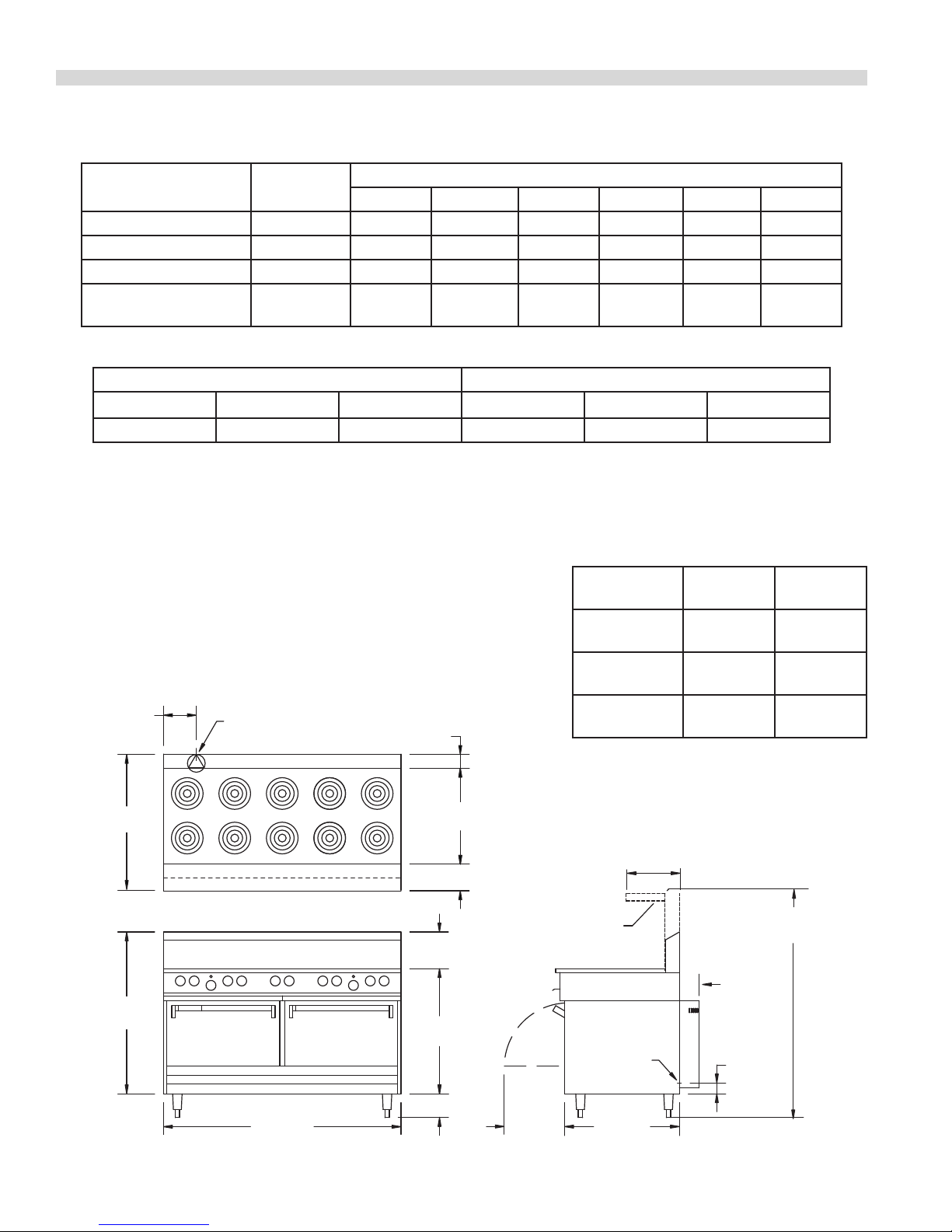
DIMENSIONS AND SPECIFICATIONS, MODELS S,SU & SS684
Model
Total Kw
Load
208V/1Ph 208V/3 Ph 240V/1Ph 240V/3 Ph 400 V/3N 415V/3N
Nominal Amps
S684* 27 127 76 110 66 — —
SS/SU684** 33 157 97 136 84 60 58
SS/SU684RC2*** 34 N/A 100 142 87 60 58
Salamander
7 N/A***** 23 29 20 4 4
Broiler****
*(All purpose tubular elements) **(Sealed -top elements, Model # SS684 in North America) *** Maximum on any 684 series range.
****Add when wired to range base (SER/SUER-680) *****Note: For 208V/1phase the salamander cannot be wired into the range.
Exterior Dimensions Oven Interior Dimensions
Height Width Depth
†
Height Width Depth
47" (1194mm) 60" (1524mm) 34-1/4" (870mm) 13-1/2" (343mm) 26-1/4” (667mm) 22" (559mm)
† With Front Rail Note: Shipping Cubic Feet is 84.5.
Ratings:
Tubular Elements - Small 6-1/2" (165mm) - 1250 Watts. Large 8-1/2" (216mm) - 2100 Watts
Sealed Elements - Small 7” (180mm) - 2000 Watts. Large 8-5/8” (220mm) - 2600 Watts
Hot Plate - (per 12"/305mm section) - Front and Rear sections each 1675 Watts, (3350 Watts total)
Griddle - (per 12"/305mm section) - 3350 Watts
Standard Oven - 4.85 kW
Convection Oven - 5.0 kW (plus 0.5kW fan motor, for 5.5kW total)
NOTE: Many local codes exist, and it is the responsibility of the Owner
and the Installer to comply with those codes.
7-1/2"
[190mm]
34-1/4"
[870mm]
REAR CABLE
ENTRANCE
3-1/2"
[829mm]
24-1/2"
[622mm]
[152mm]
NOTE: For ranges with convection oven(s), (models with
sux `RC’ or `RC2’), air circulation is required for proper
operation of fan motors. These models must not be dais
mounted or installed without legs.
6"
Installation
Clearances:
Range w/o
Salamander
Range w/
Salamander
Hot Plate
13-5/8"
[346mm]
Side Back
3” (76mm) 2” (51mm)
7” (178mm) 2” (51mm)
10”
(254mm)
—
41"
[1041mm]
60"
[1524mm]
9-1/4"
[235mm]
31-3/4"
[806mm]
6"
[152mm]
15-1/4"
[387mm]
OPTIONAL
HIGH SHELF
REAR CABLE
ENTRANCE
[737mm]
57-5/8"
[1465mm]
4-3/4"
[121 mm]
W/OPTIONAL
RC MOTOR
3"
[76mm]
29"
Part # P152 Rev 1 (01/13/10)Page 4
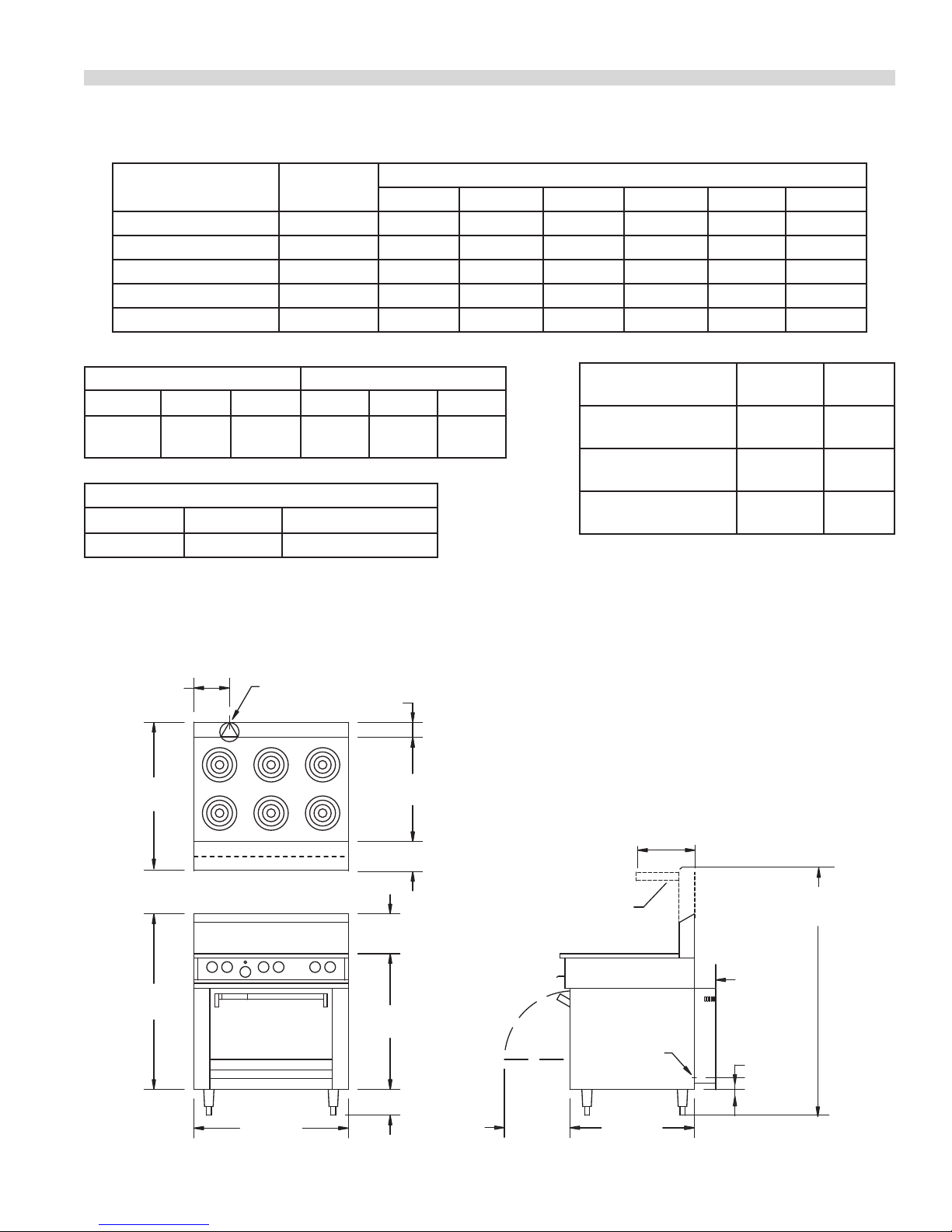
DIMENSIONS AND SPECIFICATIONS, MODELS S,SU & SS686
Model
Total Kw
Load
208V/1Ph 208V/3 Ph 240V/1Ph 240V/3 Ph 400 V/3N 415V/3N
Nominal Amps
S686* 15 72 48 62 42 — —
S686RC 16 75 51 64 44 — —
SS/SU686** 19 90 59 78 52 40 38
SS/SU686RC 20 93 62 80 54 40 38
Salamander Broiler*** 7 34 19 29 16 4 4
*Tubular elements; **Sealed -top elements, Model # SS686 in North America; ***Add when wired to range base (SER/SUER-680)
Exterior Dimensions Oven Interior Dimensions
Height Width Depth†Height Width Depth
47"
(1194mm)
†
With front rail Note: Shipping Cubic Feet is 58.5
36"
(914mm)
34-1/4"
(870mm)
13-1/2"
(343mm)
26-1/4"
(667mm)
(559mm)
Entry Clearances
Crated Uncrated Uncrated "RC" Model
22"
Installation
Clearances:
Range w/o
Salamander
Range w/
Salamander
Hot Top
Side Back
3"
(76mm)
7"
(178mm)
10"
(254mm)
45" (1143mm) 35" (889mm) 40" (1016mm)
NOTE: Many local codes exist, and it is the responsibility of the
Owner and the Installer to comply with those codes.
8-3/8"
[213mm]
34-1/4"
[870 mm]
REAR CABLE
ENTRANCE
3-1/2"
[89mm]
24-1/2"
[622mm]
Ratings:
Tubular Elements: 6-1/2" (165mm): 1250 Watts
8-1/2" (216mm): 2100 Watts
Sealed Elements: 7" (180mm): 2000 Watts
8-5/8" (220mm): 2600 Watts
Hot Tops: (per 12"/305mm section):
Front and Rear sections each 1675 Watts, (3350
Watts total)
Griddle (per 12"/305mm section): 3350 Watts
Standard Oven: 4.85 kW
Convection Oven: 5.0 kW (+0.5kW fan motor; for 5.5kW total)
NOTE: For ranges with convection oven, (models with sux `RC’),
air circulation is required for proper operation of fan motors. These
models must not be dais mounted or installed without legs.
13-5/8"
6"
[152mm]
[346mm]
2"
(51mm)
2"
(51mm)
—
41"
[1041mm]
36"
[914mm]
Part # P152 Rev 1 (01/13/10) Page 5
9-1/4"
[235mm]
31-3/4"
[806mm]
6"
[152mm]
15-1/4"
[387mm]
OPTIONAL
HIGH SHELF
REAR CABLE
ENTRANCE
[737mm]
57-5/8"
[1465mm]
4-3/4"
[121mm]
W/OPTIONAL
RC MOTOR
3"
[76mm]
29"

DIMENSIONS AND SPECIFICATIONS, RANGE MODELS
Range Sux Denitions
S/SS/SU 686/684 RC (2) -(1,2,3) (L,C,R) -(12,24,36) (L,C,R)
-12 = 12" (305 mm) wide griddle
-24 = 24" (610 mm) wide griddle
-36 = 36" (915 mm) wide griddle
- L = griddle on left hand side of range
- C = griddle in center of range
- R = griddle on right hand side of range
-1 = 12" (305mm) wide solid top
-2 = 24" (610mm) wide solid top
-3 = 36" (915mm) wide solid top
-L = Solid top on left hand side of range
-C = Solid top in center of range
-R = Solid top on right hand side of range
RC = Convection Oven
RC2 = Double convention oven base
686 = 36" (915mm) wide range
684 = 60" (1524mm) wide range
S = Sentry series range
SU = Sentry series range
CE marked design
SS = Sentry series range
with sealed top elements
Part # P152 Rev 1 (01/13/10)Page 6
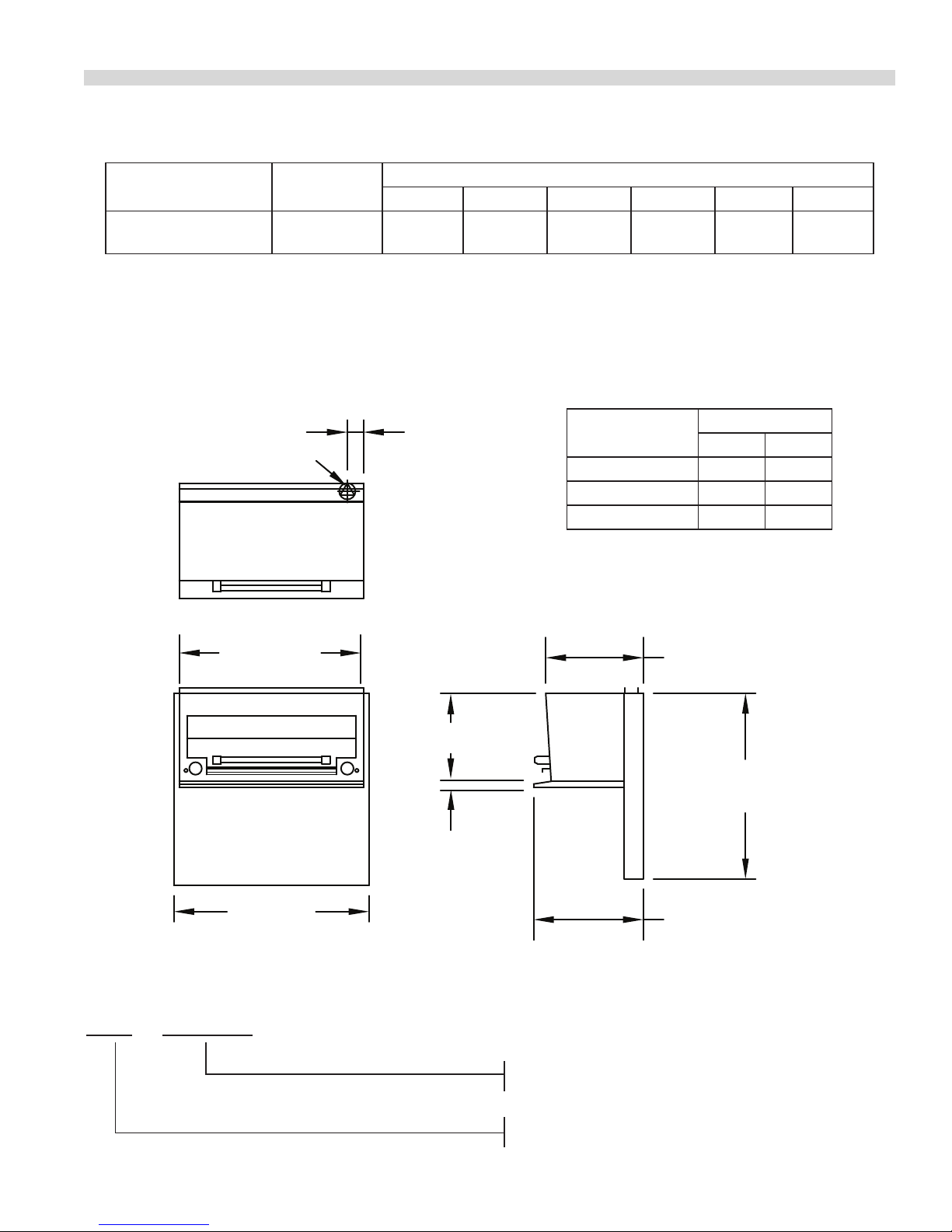
DIMENSIONS AND SPECIFICATIONS, MODELS SERC, SER-680
SU = Sentry series salamander CE marked design
Model Total Kw Load
SERC, SER-680
wired independently
Installation Notes:
Clearances from combustible surfaces should be minimum 7” (178mm) from sides, 2” (51mm) from back.
*Note: 3 phase ratings apply to SERC and SER-680 ordered separately. When a range and salamander are ordered together
it is standard for the salamander to be prewired at the factory to interconnect with the range (single phase). For further
information on ratings and connection options consult the factory.
7 34 29 29 25 15 15
208V/1Ph 208V/3 Ph 240V/1Ph 240V/3 Ph 400 V/3N 415V/3N
3"
REAR CABLE
[76mm]
ENTRANCE
TOTAL AMPS
Model
S/SUERC 11 210/95
S/SUER-686 25 176/80
S/SUER-684 35 209/95
KW Ratings
Total kW loading is 7.0 kW
Shipping
Cu Ft Lbs/Kg
34"
[864mm]
36"
[914mm]
Salamander Sux Denitions
S/SU ERC, ER-680
18"
[457mm]
16-1/4"
[413mm]
34-1/4"
[870mm]
1-1/8"
[29mm]
20-1/4"
[514mm]
-ERC = 34” (864mm) wide counter top salamander
-ER-680 = 34” (864mm) wide range mount salamander
Part # P152 Rev 1 (01/13/10) Page 7
S = Sentry series salamander

INTRODUCTION
The following instructions should be read carefully as the
manufacturer cannot be held responsible for any damage to
the property or persons by incorrect installation or operation
of the equipment.
Uncrating
1. Check the crate for possible damage sustained during
transit. Carefully remove the unit from the crate and
again check for damage. Any damage to the appliance
must be reported to the carrier immediately.
2. All packing material must be removed from the unit. The
protective material covering the stainless steel must be
removed immediately, after the unit is installed.
3. All ranges are shipped from the factory with legs or
casters tted unless specially ordered without.
4. The splash back and high shelf is packed and ordered
separately.
5. Do not remove permanently axed labels, warnings
or data plates from the appliance, for this may void
approvals and create a safety hazard.
Rating Plate
The data plate is readily accessible, located behind the lower
panel on ranges & behind the drip tray on salamanders.
It contains all the pertinent information required by the
installer.
When corresponding with the factory or your local
authorized factory service center regarding service problems
or replacement parts, be sure to refer to the particular unit
by the correct model number (including the prex and sux
letters and numbers) and the warranty serial number. The
rating plate axed to the unit contains this information.
Safety Precautions
This manual pertains to ranges and salamanders. The reader/
operator must interpret its contents to applicable needs. If
there is any question of interpretation of any of the literature
pertaining to Garland ranges or salamanders, please contact
your authorized service agency, or our customer service
department at the phone number listed on the front of this
manual or on our web site: http://www.garland-group.com.
A qualied person must make the installation of these
products in accordance with the local codes of the country of
destination.
Always follow these safety precautions when operating the
range or salamander.
1. The Unit must only be operated by qualied persons. DO
NOT operate without reading this manual and operation
manual.
2. DO NOT operate the product unless it has been properly
installed and grounded.
3. DO NOT operate the product unless all service and access
panels are in place and fastened properly.
4 DO NOT attempt to repair or replace any part of this
product unless all main power supplies have been
disconnected.
WARNING: to avoid personal injury: Use Extreme caution
in setting up, operating and cleaning the product to avoid
coming in contact with the hot grill surfaces or hot grease.
Suitable protective clothing should be worn to prevent the
risk of burns.
WARNING: this appliance must not be cleaned with a water
jet.
Part # P152 Rev 1 (01/13/10)Page 8
INSTALLATION
This equipment must be installed by a competent factory
trained, certied, licensed and / or authorized service
or installation person. Electrical work must be installed
by a qualied person as required by the local electrical
authorities.
WARNING: This appliance must be grounded.
CAUTION: Prior to installation check the electrical supply to
ensure the input voltage and phase match the equipment
voltage rating and phase as shown on the rating plate.
Clearances
The space in which the appliance is to be positioned must
include the minimum installation clearances to combustible
surfaces.
MINIMUM INSTALLATION CLEARANCES
Clearance To Combustible Material
Models
Location
Top * * *
Sides 3” (76mm) 10” (254mm) 7” (178mm)
Rear 2” (51mm) 2” (51mm) 2” (51mm)
* NOTE: Garland recommends equipment be installed under
a ventilation canopy.
Ranges
Ranges
c/w Hot Top
Salamander
Positioning
The range should be installed on a rm, smooth and level
oor designed to withstand the weight of the fully laden
appliance. Refer to dimension and specications for weights.
Place the range or salamander in desired position and level
from side to side and back to front and diagonally. This
leveling must be done with the unit under the hood and in
it’s normal operating position. If the range is to be dais or
cove mounted ,the base on which it is to be set should be
level. If it is not, the range must be shimmed to level.
Legs
All ranges are shipped from the factory with legs installed
unless otherwise specied. When the range is specied for
dais or cove base mounting, it is shipped less legs. Legs must
be adjusted to a minimum height of 6” (152mm) in order to
comply with NSF standards.
Casters
1. The front casters on the unit are equipped with brakes to
limit the movement of the range without depending on
the electrical connection to limit appliance movement.
2. A restraint can be attached to the unit near the electric
connection. If the restraint is disconnected, be sure to
reconnect it after the range has been returned to its
originally installed position.
LOCATION
Models Type Of Floor Or Base
Ranges Combustible
Ranges c/w Hot Top Combustible
Salamander Non-Combustible
IMPORTANT: For ranges with convention oven (models with
sux “RC”), air circulation is required for proper operation of
the fan motors. Allow 1” (25mm) rear clearance for ventilation
of the motor.
Adequate clearance must be provided for servicing,
ventilation and proper operation. The range must be kept
clear of combustible material.
Ventilation Air
The area in which the appliance is installed must be
adequately ventilated to provide air for removal of steam,
heat generated by the appliance, etc. These products are
recommended to be installed under a ventilation hood.
Proper operation of exhaust fans (proper speed, rotation and
adjustment) is essential. The hood, and the lters must be
cleaned on a regular bases and kept grease free.
Installation Of Range Mount Salamander
1. The rear of the range must be easily accessible.
2. Place the salamander in position on the range. Slide the
uprights into the opening at the oven rear. Secure the
salamander uprights to the range with the hex head bolts
provided.
Part # P152 Rev 1 (01/13/10) Page 9

INSTALLATION continued
3. Remove the terminal block access cover.
4. Pass the wires though cable entrance hole.
5. Secure the cable connector
6. Terminate the salamander wire at the terminal block
provided (Red to L1, Black to L2 or N, Green to GRN or E).
NOTE: When mounting a salamander over an existing range
in the eld, an independent fussed connection must be
made though the knock out plate provided in the main back
of the salamander.
Assembly of Backguard/High Shelf
The back guard or high shelf will have been shipped
separately. To install, put the backguard/high shelf on the
rear of the range, slipping the uprights into the opening on
each burner box side. Fasten the upright to the burner box
side with four hex fasteners provided.
Code Requirements
The Garland S/SS680 series complies with the standards CSA
C22.2 no.109 – latest edition, the UL197 – latest edition and
the NSF#4 – latest edition. The installation and connection
of this appliance must comply with current codes. In Canada
– The Canadian Electrical Code Part 1 and in the USA – The
National Electrical Code.
NOTE: A means of disconnection from the supply having
a contact separation of at least 3 mm in all poles must be
incorporated in the xed wiring.
This equipment is intended to be installed with xed
permanent wiring.
WARNING: This appliance must be grounded.
Single And Three Phase Connection
Unless otherwise noted, all ranges are shipped from the
factory for three phase connection. Salamanders are shipped
from the factory for single phase connection. A wiring
diagram is attached to the rear of each appliance. Visually
check all electrical connections. The range is wired at the
factory as specied on the order. If it is necessary to change
the phasing refer to the wiring diagram.
Commissioning
Ensure all circuit breakers located in the lower compartment
are set to the ON (1) position.
1. Ensure that all controls are in the OFF position and turn
on the main electrical supply.
2. Operate each section of the range or salamander in
accordance with the instructions given in the Use’s
Manual.
The Garland SU680 series complies with the essential
requirements of the Directives 73/23/EEC, 89/336/EEC,
89/392/EEC, 93/68/EEC and the standards, EN60335,
IEC801.2, IEC801.3, IEC801.4, IEC801.5, IEC801.6 and
IEC801.11.
Electrical Supply
Before attempting the electrical connection, the rating plate
should be checked to ensure that the equipment’s electrical
characteristics and supply electrical characteristics agree. On
ranges and salamanders the supply entrance is located at the
rear or alternatively on the main bottom. The supply terminal
block is accessible from the front. The electrical supply must
be adequate for the voltage, phase, and current marked on
the rating plate.
3. Check that the product functions correctly and that the
voltage supply to the unit does not drop more than 5%
when all sections are operated simultaneously.
When the operation has been checked, hand the OPERATING
INSTRUCTIONS to the User or purchaser for retention and
instruct them in the ecient and safe operation of the
appliance.
Part # P152 Rev 1 (01/13/10)Page 10
MAINTENANCE AND CLEANING
Regular servicing by a competent person is recommended to
ensure safe and ecient performance of the appliance.
WARNING: Turn o the electrical mains before
commencing any service work.
Thermostat Calibration
Oven
It is normal for an electromechanical thermostat to cycle with
a 45°F - 50° F (25°C - 28°C) range when checking calibration
allow the thermostat to cycle a minimum of two times.
1. Place the thermocouple of the test instrument in the
center of the oven.
2. Turn the oven temperature control dial to 400° F (205°
C). In order to allow the oven temperature to stabilize,
the oven control must be allowed to cycle twice before
taking a test reading.
3. Check the temperature reading just when the control
cycles “OFF” as indicated by the cycling pilot lamp. If the
temperature does not read with in 15° F (8°C) of the dial
setting, recalibrate as follows:
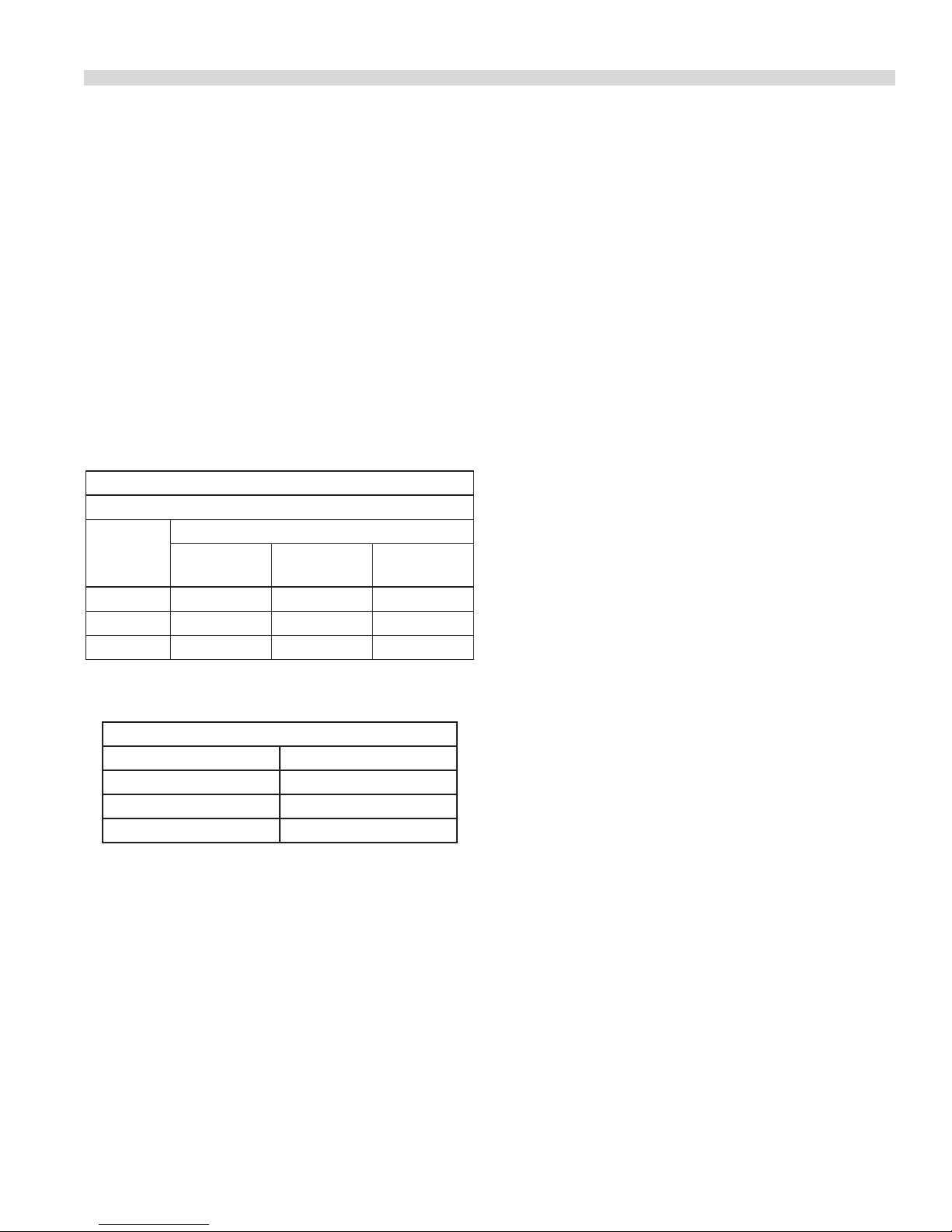
4. Carefully remove the thermostat dial, not disturbing the
dial setting.
5. Hold the thermostat shaft steady with a small at blade
screw driver. Turn the calibration screw located inside the
shaft clockwise to decrease the temperature and counter
clockwise to increase the temperature. NOTE: each ¼ turn
of the screw will create a change of approximately 35° F
(20°C).
6. Replace the thermostat dial and repeat steps 1 though 3
to verify that the correct adjustment has been made.
Dial Shaft
Calibration Screw Head
Calibration
Screw Head
1/4" Turn
Increase
Decrease
Griddle
1. Use a test instrument with a special disc type
thermocouple or a reliable surface type pyrometer. NOTE:
a drop of oil on the face of the disc will provide better
contact with the plate.
2. Set all griddle thermostats to 350°F (177°C). In order
to allow the griddle temperature to stabilize, the
thermostats must be allowed to cycle twice before taking
a test reading.
3. Check the griddle temperature when the thermostat just
cycles “OFF” by placing the thermocouple rmly on the
griddle directly about the sensing bulb of the thermostat.
The reading should be between 335° F (168°C) and 365°
F and (185°C). If the reading is outside of these limits,
calibrate as follows:
4. Carefully remove the dial, not disturbing the shaft
position.
5. Hold the shaft steady and with a small at screw
driver turn the calibration screw located inside the
shaft clockwise to decrease temperature and counter
clockwise to increase temperature. NOTE: Each ¼ turn
of the screw will create a change of approximately 35° F
(20°C).
6. Replace the thermostat dial and repeat steps 1 through 3
verify that a correct adjustment has been made.
Part # P152 Rev 1 (01/13/10) Page 11

MAINTENANCE AND CLEANING continued
Miscellaneous
1. Grease the door hinges and check for loose fasteners.
Tighten as necessary.
2. Wire brush the surface of the griddle to remove baked
on material, wash with hot water, dry thoroughly. Lightly
coat the surface with vegetable oil to prevent rusting.
REPLACEMENT OF PARTS
Servicing must be carried out by competent persons in
accordance with the law.
WARNING: Turn o the electrical mains before commencing
any servicing work.
Door Switch
1. Drop the lower kick panel.
2. Remove the screws securing the door switch and
mounting brackets and remove screws securing the door
switch.
3. Remove the terminal cover and disconnect the wires
from the terminals on the body of the switch.
4. Replace the faulty door switch.
5. Make certain that the newly installed door switch is
properly adjusted so as the interrupt the power supply
to the control system and fan motor when the door is
opened.
Fan Cook/Cool Down Switch
3. Wipe exposed cleanable surfaces with a mild detergent
and hot water. Stubborn residue may be removed with
a light weight non-metallic scouring pad. Stainless steel
areas should be washed with a mild detergent, hot water
and a soft cloth. If necessary use a nonmetallic scouring
pad always rub in the of the grain in the metal to prevent
scratching. NEVER USE STEEL WOOL.
4. Clean the oven racks shelves and guides with hot soapy
water and dry thoroughly. Clean the oven interior with a
propriety oven cleaner following instructions.
4. Replace the switch and reassemble in reverse order.
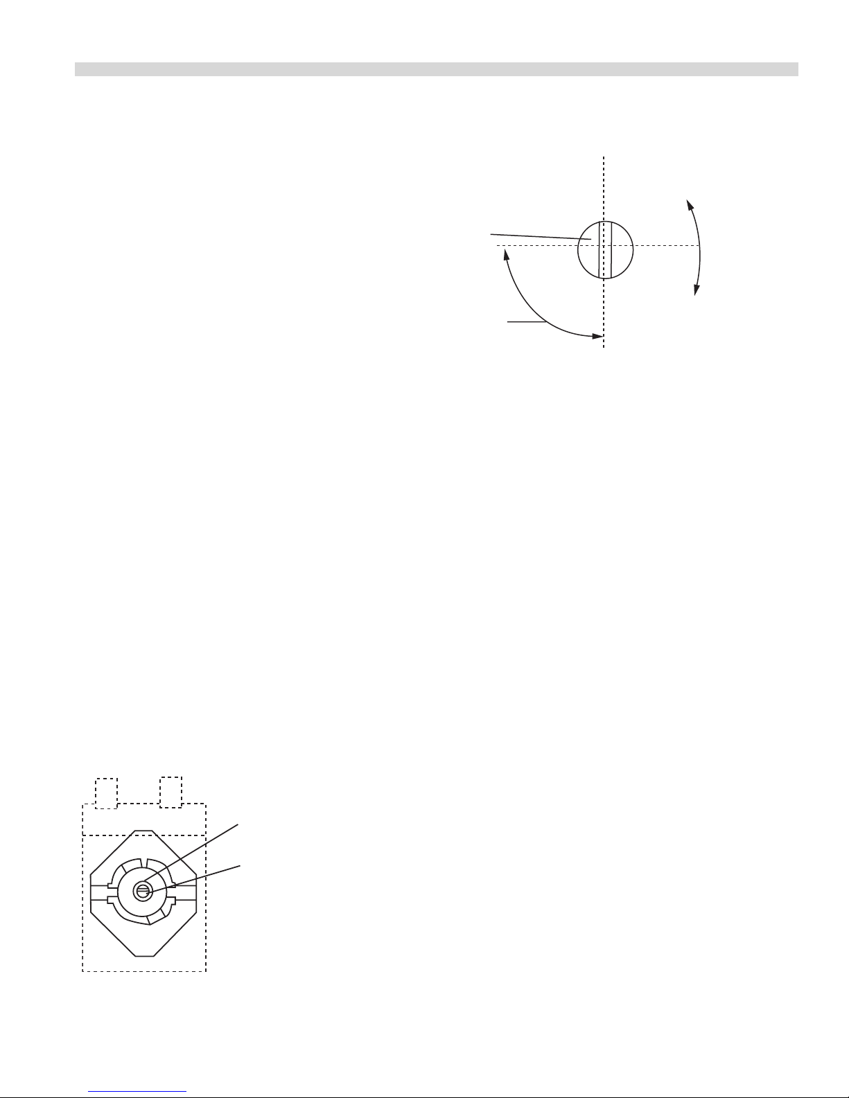
Thermostat
1. Remove the screws securing the front panel to the front
rail and drop the panel.
2. Disconnect the wires from the taps on the thermostat.
3. Remove the dial from the thermostat and the screws
securing the thermostat body to the control panel.
4. Remove the wires from the thermostat terminals. Be sure
to note which wire connects to which terminal on the
thermostat.
5. Remove the thermostat bulb.
6. Replace the faulty thermostat and reassemble in reverse
order.
Heat On Lamp
1. Remove the screws securing the front panel to the front
rail and drop the panel.
1. Remove the screws securing the front panel to the front
rail and drop the panel.
2. Disconnect the wires from the terminals on the switch.
3. Depress the tabs of the switch body and push the switch
through the opening in the control panel.
2. Disconnect the supply wires to the lamp and remove the
faulty lamp.
3 Reassemble in the reverse order.
Part # P152 Rev 1 (01/13/10)Page 12
REPLACEMENT OF PARTS continued
Motor
1. Open the door.
2. Remove the oven racks and guides
3. Remove the two (2) wing screws securing the fan guard
and remove the guard.
4. Using a hex head wrench loosen the screw securing the
blower wheel to the motor shaft and remove the wheel.
5. Remove the four (4) screws securing the motor mount
plate to the oven casing back and pull the plate froward
into the oven compartment.
6. Disconnect the motor wire connections (note which
wires connect to which) and replace faulty motor.
7. Reassemble in reverse order.
TROUBLE SHOOTING
NOTE: Servicing must be carried out by competent persons in accordance with the law.
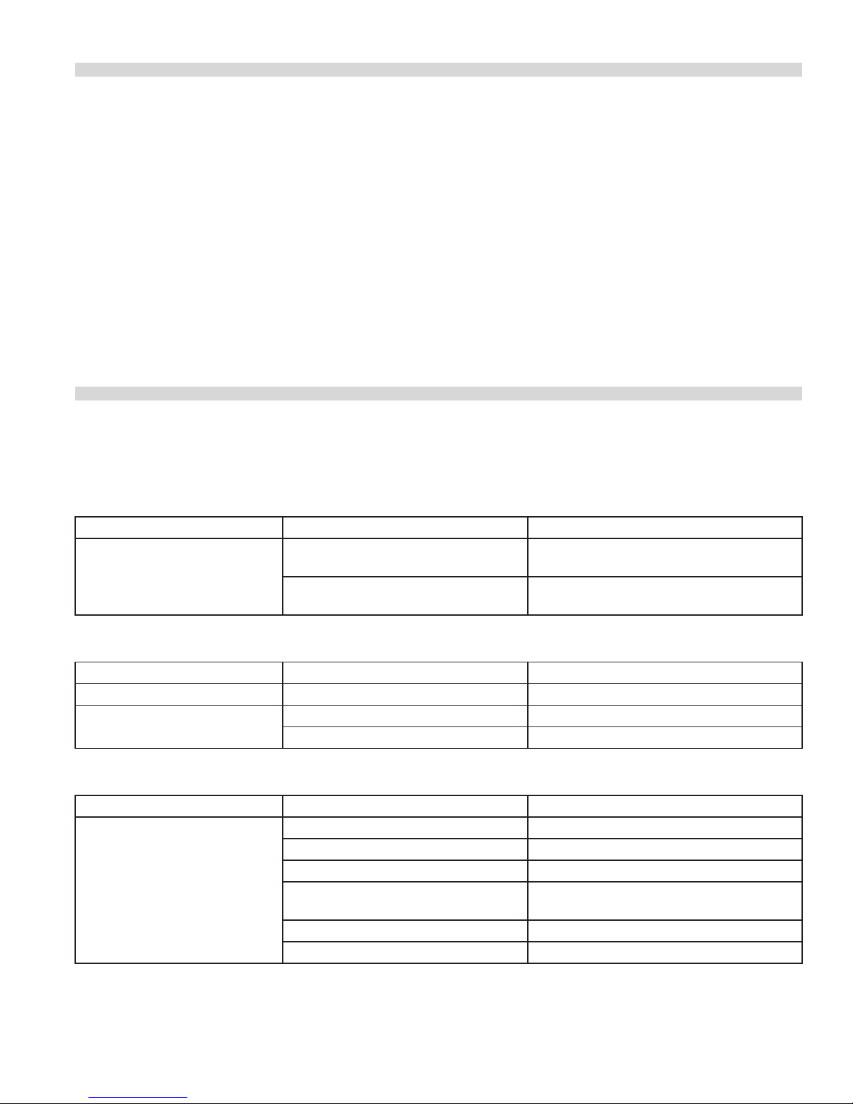
Griddle Diagnostics
PROBLEM POSSIBLE CAUSE SOLUTION
Griddle heating unevenly.
Adjacent griddle is operating at a
dierent temperature.
Griddle was not thoroughly heated
before using.
Check adjacent griddle section.
Allow more time for griddle to saturate.
Increase warm-up time.
Hot Top or Open Tubular Diagnostics
PROBLEM POSSIBLE CAUSE SOLUTION
Top to hot or too cold. Defective innite switch. Replace innite switch.
Top not heating at all. Defective element Replace element.
Defective innite switch. Replace Innite switch.
Sealed Hotplate Diagnostics
PROBLEM POSSIBLE CAUSE SOLUTION
Water in pot does not Boil. Water
takes to long to Boil. Switch set to
position ‘6’.
Pot has irregular bottom. Use at bottom pot.
Pot too large for element size. Use smaller diameter pot.
Pot too small for element size. Use larger diameter pot.
Element was preheated before pot was
placed on element.
One element circuit may be defective. Replace heating element.
Six heat switch may be defective. Replace 6 heat switch.
Allow element to cool. Protector will reset.
Part # P152 Rev 1 (01/13/10) Page 13
TROUBLE SHOOTING continued
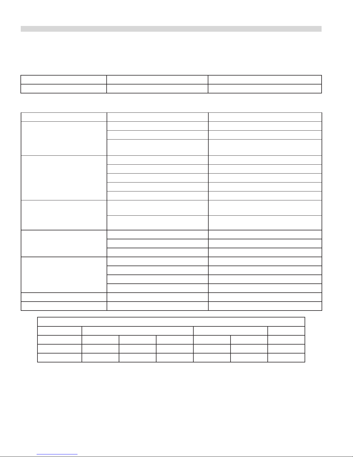
Oven Diagnostics
PROBLEM POSSIBLE CAUSE SOLUTION
Oven too hot or not hot enough. Thermostat out of calibration. Check Thermostat/replace thermostat.
RC Oven Diagnostics
PROBLEM POSSIBLE CAUSE SOLUTION
Cook/Cool Down Switch set to
“Cook” position. Light o. Motor
not working.
No Power to Oven. Check power supply.
Defective Cook/Cool Down switch. Replace switch.
Faulty wiring. Check condition of wires and all connections.
Cook/Cool Down Switch set to
“Cook” position. Light on. Motor
not working.
Cook/Cook Down Switch set to
“Cook” Position. Motor working,
thermostat set to temperature,
lamp “on”, oven not heating.
Noisy motor. Blower wheel rubbing on oven baed. Adjust blower wheel.
Cook/Cool Down switch set to
“Cool Down”, motor not working.
Oven too hot or not hot enough. Thermostat out of calibration. Check calibration/replace thermostat
Oven doors will not stay closed. Broken or damaged door spring. Replace door spring.
Application Boiling, Frying, Braising Simmering Warming
Dial Setting 6 5 4 3 2 1
8-5/8” (220mm) 2600W 1750W 1300W 450W 340W 240W
7” (180mm) 2000W 1400W 950W 450W 305W 200W
Defective door switch. Replace switch.
Oven door partially open. Close door.
Door switch out of alignment. Align switch.
Defective Motor. Replace Motor.
Faulty wiring. Check condition of wires and all connections.
Relay RL1 is defective. Replace relay.
Defective heating element or wiring. Replace heating element or repair wiring.
Blower wheel loose on motor shaft. Retighten blower wheel.
Defective Motor. Replace Motor.
Defective Cook/Cool Down switch. Replace switch.
Defective door switch. Replace switch.
Door switch out of alignment. Align switch.
Faulty wiring. Check condition of wires and all connections.
Sealed Hoptate Wattages and Applications
Part # P152 Rev 1 (01/13/10)Page 14

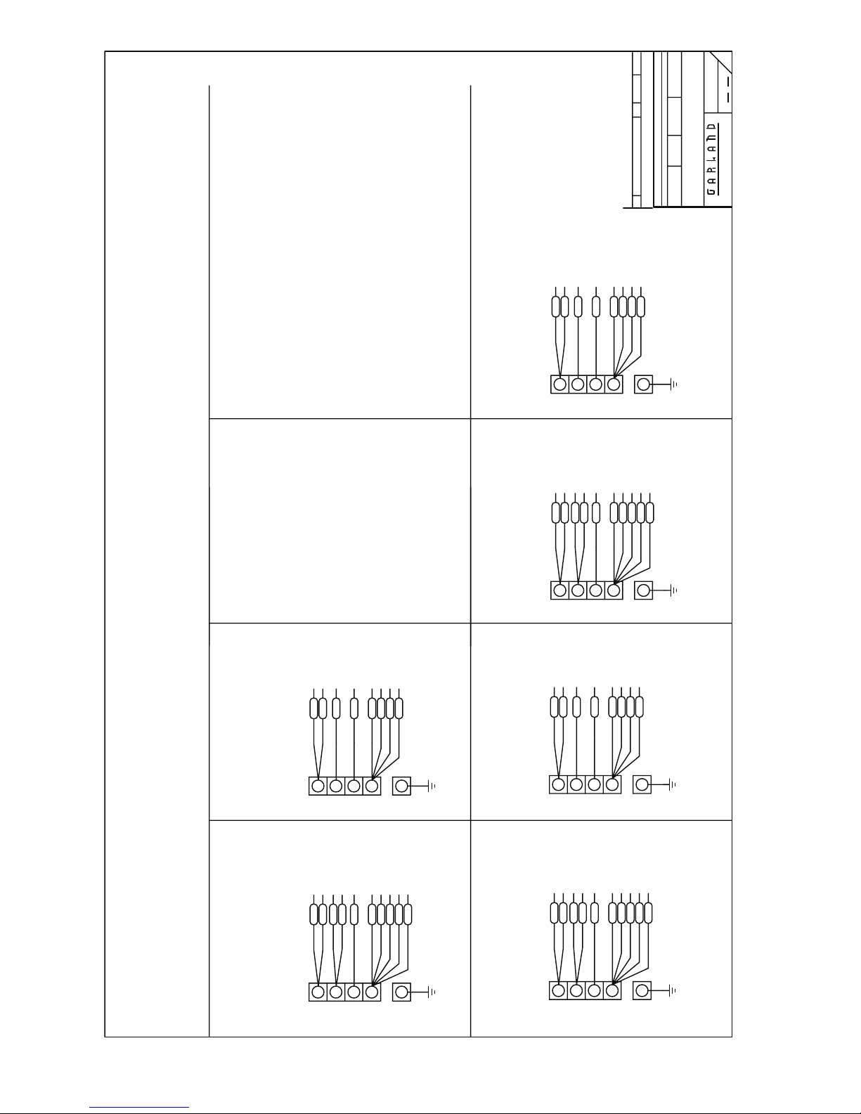
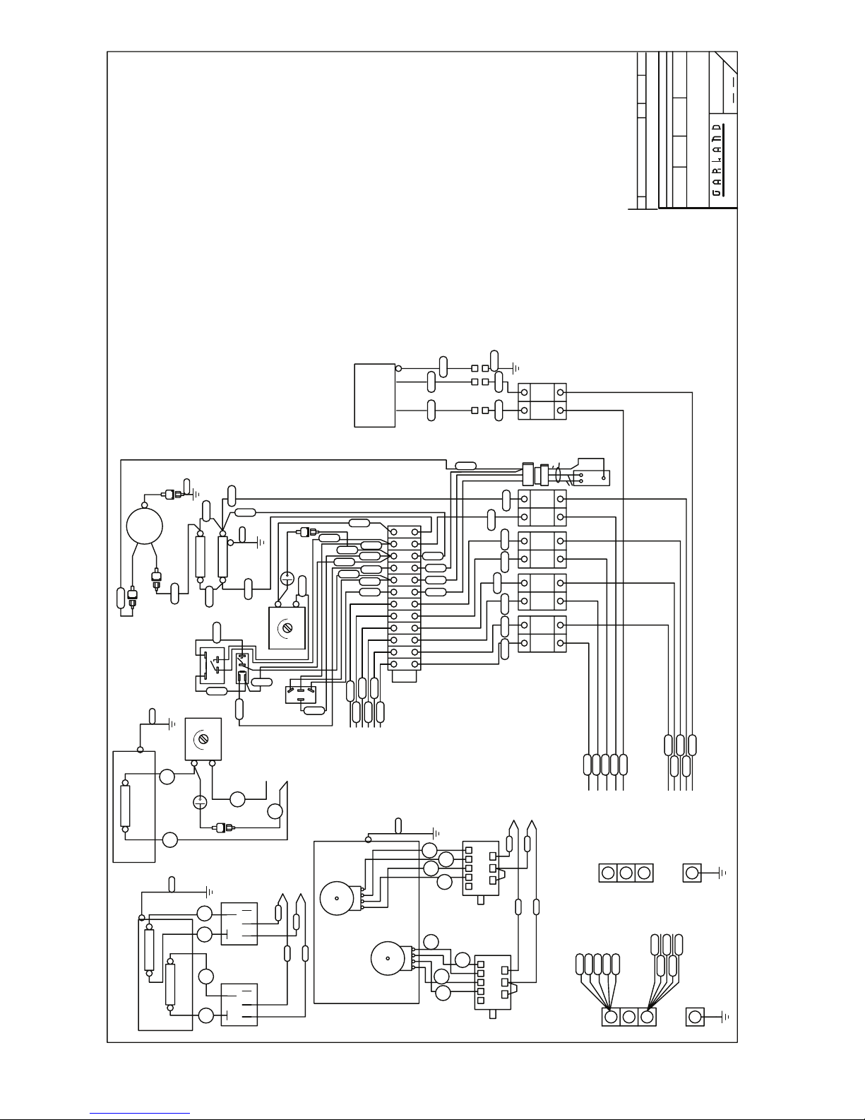
APPENDIX
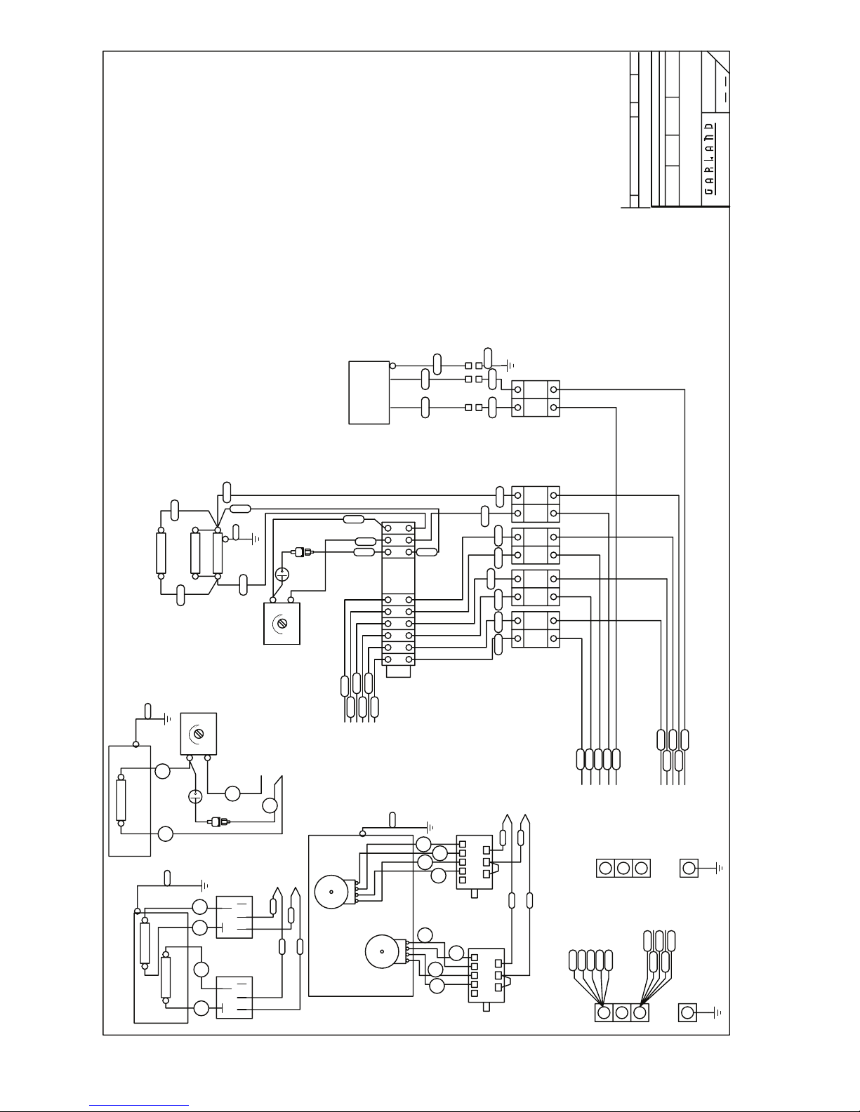
Wiring Diagrams and Loading Charts
Part # P152 Rev 1 (01/13/10) Page 15
REV.#
DATE
DR.DESCRIPTION
REVISIONS
ALL DIMENSIONS ARE IN INCHES
TOLERANCE ±0.015" UNLESS OTHERWISE SPECIFIED
REV
:
DATE
:
SCALE
:
CHK. BY
:
DR.
S680 SERIES
TITLE:
21
SHT OF
2693100
WIRING DIAGRAM S/SS686
COMMERCIAL RANGES LIMITED
MISSISSAUGA, ONTARIO, CANADA
APR 23,1999NAVC
HOT TOP / (OPEN TOP)
3.35kW
3.35kW TOTAL /(8"=2.1kW, 6"=1.25kW)
UPPER
OVEN ELEMENTS 4.85kW
E4
GRIDDLE
1675W
750W
G4
G2
E3
1675W
TB1-10f
TB1-12c
1900W
INNER
H1 H2
H2H1
2200W
OUTER
40°-230°C
GRIDDLE THERMOSTAT
H1
H2
H1
H2
O2(4)
OVEN
S(8)
S(5)
S(7)S(6)
ER 7kW
SALAMANDER
S(3) S(4)
SALAMANDER
30A_0A_0A_0A 40A
TB1-10a
E1b
TB1-12a
65°-290°C
OVEN THERMOSTAT
N (BLACK)
L (RED)
G3
G1
N (BLACK)
L1 (RED)
P
OT4
L2
OT3
OT2
OT1
TB1-12b
12
TB1-11a
TB1-10c
TB1-2
TB1-4
TB1-6
TB1-1
TB1-3
TB1-5
LNLNL
N
TOP 1
TOP 2
TOP 3
E2
3421
TB1-10a
1 2 3 4 5 6 10 11
TB1
4
3
1
2
3
3421
4
1
P L1
L1
L2
SEALED ELEMENT
2.6kW, 220mm
2.0kW, 180mm
2
O1(4)
O1(3)
T3(4)T3(3)
T2(4)
_0A _0A 30A 40A
_0A
T1(3) T1(4) T2(3)
TOP 1 TOP 2 TOP 3 OVEN
4600W TOPS = 30A
3350W TOPS = 20A
T1(2)
T3(2)
S(2)
T1(1)
T2(1)
T3(1)
O1(1)
S(1)
L (RED)
N (BLACK)
ST4
43125
6 HEAT SWITCH
ST3
P2
P1
P3
ST1
ST2
SEE TERMINAL BLOCK
43125
P2
P1
P3
6 HEAT SWITCH
TOP 3 RED
TOP 2 RED
TOP 1 RED
OVEN 1 RED
SALAMANDER RED
X
Y
3 PHASE
CONNECTION SHEETS
RED
RED
RED
RED
RED
T1(1)
T2(1)
T3(1)
O1(1)
S(1)
X
Y
1 PHASE
T2(2)
O1(2)
TOP 3 BLACK
TOP 2 BLACK
TOP 1 BLACK
OVEN 1 BLACK
SALAMANDER BLACK
Z
BLACK
T1(2)
Z
G
BLACK
BLACK
BLACK
BLACK
T3(2)
S(2)
O1(2)
T2(2)
G
Part # P152 Rev 1 (01/13/10)Page 16
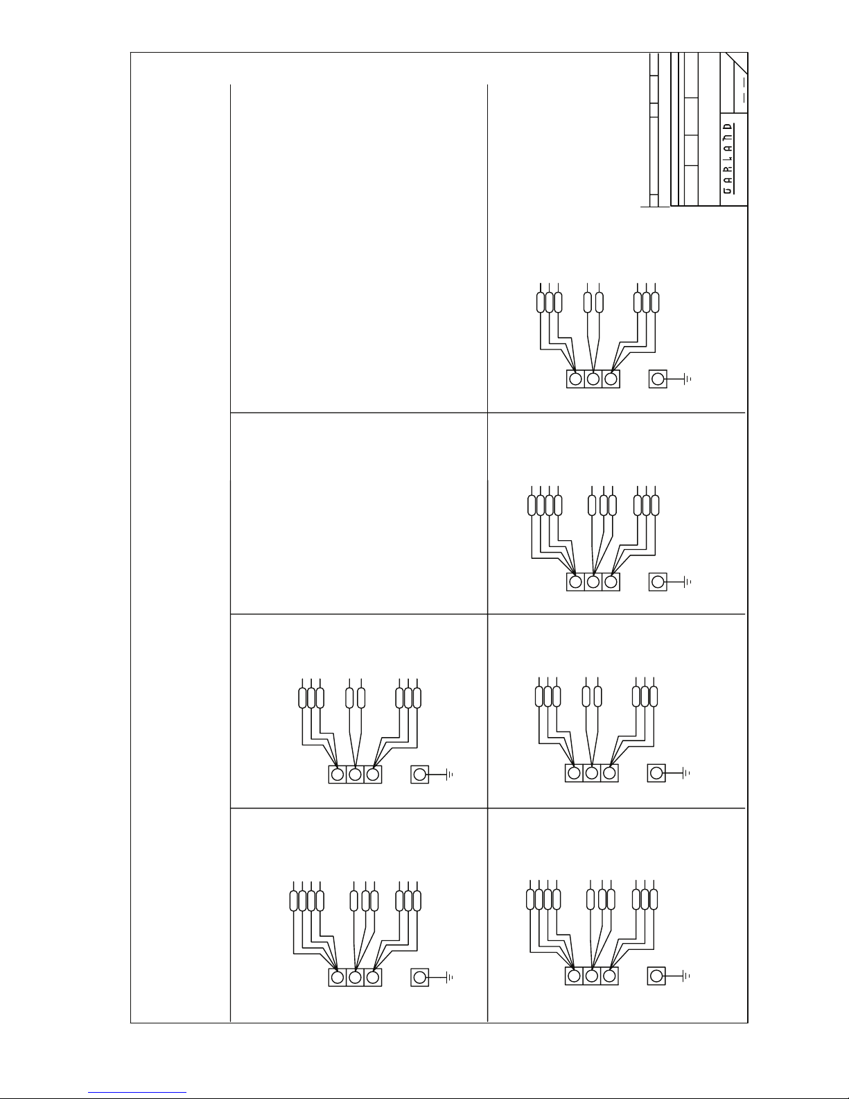
TOP 1 RED
TOP 2 RED
TOP 3 RED
REV.#
DATE
DR.DESCRIPTION
REVISIONS
TOLERANCE ±0.015" UNLESS OTHERWISE SPECIFIED
REV
TOP 3 BLACK
TOP 1 BLACK
TOP 2 BLACK
OVEN 1 RED
OVEN 1 BLACK
S680 SERIES
WIRING DIAGRAM S/SS686
TITLE:
22
SHT OF
2693100
COMMERCIAL RANGES LIMITED
MISSISSAUGA, ONTARIO, CANADA
:
APR 23,1999NAVC
DATE
:
SCALE
:
ALL DIMENSIONS ARE IN INCHES
CHK. BY
:
DR.
TOP 1 RED
T1(1)
TOP 2 RED
T2(1)
TOP 3 RED
T3(1)
OVEN 1 RED
O1(1)
T1(1)
GROUP 2
NO SALMANDER
TOP 1 RED
TOP 2 RED
T1(1)
T2(1)
GROUP 2
WITH SALMANDER
TOP 2 BLACK
TOP 1 BLACK
T1(2)
T2(2)
TOP 3 BLACK
T3(2)
OVEN 1 BLACK
O1(2)
TOP 1 RED
T1(1)
TOP 3 RED
T3(1)
TOP 2 RED
T2(1)
T3(1)
3 PHASE
OVEN 1 RED
O1(1)
3 PHASE
TOP 3 RED
O1(1)
Z
X
Y
TOP 3 BLACK
SALAMANDER RED
T3(2)
O1(2)
S(1)
Z
X
Y
TOP 3 BLACK
OVEN 1 RED
T3(2)
O1(1)
T2(2)
T3(1)
T2(1)
O1(2)
T3(2)
T1(2)
SS686 Models:
-12R, -1L-12R, -1R, -1R-12L,
-24L
G
TOP 2 BLACK
TOP 1 BLACK
OVEN 1 BLACK
T1(2)
T2(2)
SALAMANDER BLACK
S(2)
SS686 Models:
-12R, -1L-12R, -1R, -1R-12L,
-24L
G
OVEN 1 BLACK
TOP 1 BLACK
TOP 2 BLACK
O1(2)
T2(2)
T1(2)
GROUP 3
NO SALMANDER
GROUP 3
WITH SALMANDER
Part # P152 Rev 1 (01/13/10) Page 17
TOP 1 RED
T1(1)
TOP 2 RED
T2(1)
TOP 3 RED
T3(1)
3 PHASE
OVEN 1 RED
O1(1)
3 PHASE
S/SS686 Models:
-STD, -12L, -1C, -1C-12L,
-1L, -1L-24R, -1R-24L,
SS686 Models:
-1C-12R, -24R, -2R
Z
X
Y
SALAMANDER RED
OVEN 1 BLACK
TOP 1 BLACK
T1(2)
O1(2)
S(1)
Z
X
Y
TOP 2 BLACK
T2(2)
TOP 3 BLACK
T3(2)
G
SALAMANDER BLACK
S(2)
G
SS686 Models:
-1C-12R, -24R, -2R
GROUP 1
NO SALMANDER
TOP 3 RED
TOP 2 RED
TOP 1 RED
T3(1)
T2(1)
T1(1)
GROUP 1
WITH SALMANDER
3 PHASE
OVEN 1 RED
O1(1)
3 PHASE
X
Y
SALAMANDER RED
S(1)
X
Y
Z
TOP 2 BLACK
OVEN 1 BLACK
T2(2)
O1(2)
Z
G
TOP 3 BLACK
TOP 1 BLACK
SALAMANDER BLACK
S(2)
T3(2)
T1(2)
G
-2L, -2L-12R, -2R-12L, -36
S/SS686 Models:
-STD, -12L, -1C, -1C-12L,
-1L, -1L-24R, -1R-24L,
-2L, -2L-12R, -2R-12L, -36
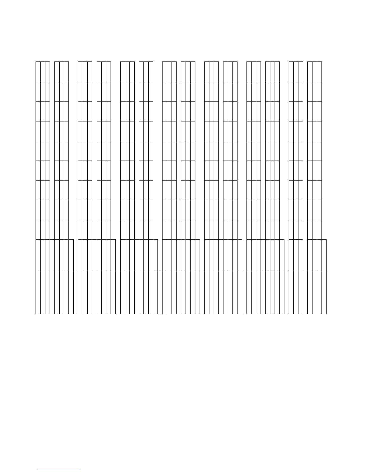
Phase grouping Loading chart
X-Z Top 1, Top 2 18.65 208 9.20 4.60 4.85 58.51 59.43 39.35 89.66
X-Y Top 3 18.65 240 9.20 4.60 4.85 50.71 51.50 34.10 77.71
Y-Z Oven
X-Z Top 1, Top 3 25.65 208 9.20 9.45 7.00 77.65 67.66 68.74 123.32
X-Y Top 2, Oven 25.65 240 9.20 9.45 7.00 67.30 58.64 59.58 106.88
Y-Z Salamander
X-Z Top 1, Top 2 17.40 208 7.95 4.60 4.85 52.87 53.81 39.35 83.65
X-Y Top 3 17.40 240 7.95 4.60 4.85 45.82 46.64 34.10 72.50
Y-Z Oven
X-Z Top 1, Top 2 24.40 208 7.95 9.45 7.00 72.54 62.29 68.74 117.31
X-Y Top 3, Oven 24.40 240 7.95 9.45 7.00 62.86 53.98 59.58 101.67
Y-Z Salamander
X-Z Top 1, Top 3 17.40 208 7.95 4.60 4.85 52.87 53.81 39.35 83.65
X-Y Top 2 17.40 240 7.95 4.60 4.85 45.82 46.64 34.10 72.50
Y-Z Oven
X-Z Top 1, Top 3 24.40 208 7.95 9.45 7.00 72.54 62.29 68.74 117.31
X-Y Top 2, Oven 24.40 240 7.95 9.45 7.00 62.86 53.98 59.58 101.67
Y-Z Salamander
X-Z Top 1, Top 2 16.15 208 6.70 4.60 4.85 47.32 48.29 39.35 77.64
X-Y Top 3 16.15 240 6.70 4.60 4.85 41.01 41.86 34.10 67.29
Y-Z Oven
X-Z Top 2, Top 3 23.15 208 6.70 9.45 7.00 67.57 57.05 68.74 111.30
X-Y Top 1, Oven 23.15 240 6.70 9.45 7.00 58.56 49.44 59.58 96.46
Y-Z Salamander
X-Z Top 1, Top 3 16.15 208 6.70 4.60 4.85 47.32 48.29 39.35 77.64
X-Y Top 2 16.15 240 6.70 4.60 4.85 41.01 41.86 34.10 67.29
Y-Z Oven
X-Z Top 1, Top 3 23.15 208 6.70 9.45 7.00 67.57 57.05 68.74 111.30
X-Y Top 2, Oven 23.15 240 6.70 9.45 7.00 58.56 49.44 59.58 96.46
Y-Z Salamander
X-Z Top 2, Top 3 16.15 208 6.70 4.60 4.85 47.32 48.29 39.35 77.64
X-Y Top 1 16.15 240 6.70 4.60 4.85 41.01 41.86 34.10 67.29
Y-Z Oven
X-Z Top 2, Top 3 23.15 208 6.70 9.45 7.00 67.57 57.05 68.74 111.30
X-Y Top 1, Oven 23.15 240 6.70 9.45 7.00 58.56 49.44 59.58 96.46
Y-Z Salamander
X-Z Top 1, Top 2 14.90 208 6.70 3.35 4.85 42.61 48.29 34.33 71.63
X-Y Top 3 14.90 240 6.70 3.35 4.85 36.93 41.86 29.75 62.08
Y-Z Oven
X-Z Top 1, Top 3 21.90 208 6.70 8.20 7.00 62.14 57.05 63.35 105.29
X-Y Top 2, Oven 21.90 240 6.70 8.20 7.00 53.86 49.44 54.91 91.25
Y-Z Salamander 2
MODEL
WITH SALAMANDER domestic (delta) load Total kW voltage kW X-Z kW X-Y kW Y-Z A X A Y A Z A 1 phase
SS686 STD NO SALAMANDER domestic (delta) load Total kW voltage kW X-Z kW X-Y kW Y-Z A X A Y A Z A 1 phase
NO SALAMANDER domestic (delta) load Total kW voltage kW X-Z kW X-Y kW Y-Z A X A Y A Z A 1 phase
SS686-1L
SS686-1C
SS686-12L
WITH SALAMANDER domestic (delta) load Total kW voltage kW X-Z kW X-Y kW Y-Z A X A Y A Z A 1 phase
NO SALAMANDER domestic (delta) load Total kW voltage kW X-Z kW X-Y kW Y-Z A X A Y A Z A 1 phase
SS686-1R
SS686-12R
WITH SALAMANDER domestic (delta) load Total kW voltage kW X-Z kW X-Y kW Y-Z A X A Y A Z A 1 phase
NO SALAMANDER domestic (delta) load Total kW voltage kW X-Z kW X-Y kW Y-Z A X A Y A Z A 1 phase
SS686-2L
SS686-1C-12L
SS686-24L
WITH SALAMANDER domestic (delta) load Total kW voltage kW X-Z kW X-Y kW Y-Z A X A Y A Z A 1 phase
NO SALAMANDER domestic (delta) load Total kW voltage kW X-Z kW X-Y kW Y-Z A X A Y A Z A 1 phase
SS686-1R-12L
SS686-1L-12R
WITH SALAMANDER domestic (delta) load Total kW voltage kW X-Z kW X-Y kW Y-Z A X A Y A Z A 1 phase
NO SALAMANDER domestic (delta) load Total kW voltage kW X-Z kW X-Y kW Y-Z A X A Y AZ A 1 phase
SS686-2R
SS686-1C-12R
SS686-24R
Part # P152 Rev 1 (01/13/10)Page 18
WITH SALAMANDER domestic (delta) load Total kW voltage kW X-Z kW X-Y kW Y-Z A X A Y A Z A 1 phase
NO SALAMANDER domestic (delta) load Total kW voltage kW X-Z kW X-Y kW Y-Z A X A Y AZ A 1phase
SS686-2L-12R
SS686-1L-24R
SS686-2R-12L
WITH SALAMANDER domestic (delta) load Total kW voltage kW X-Z kW X-Y kW Y-Z A X A Y A Z A 1 phase
SS686-1R-24L
SS686-36
SS686-1R-24L
S686 all models
REV.#
DATE
DR.DESCRIPTION
REVISIONS
ALL DIMENSIONS ARE IN INCHES
TOLERANCE ±0.015" UNLESS OTHERWISE SPECIFIED
REV
DATE
:
SCALE
:
CHK. BY
:
DR.
:
APR 26,1999NAVC
S680 SERIES
WIRING DIAGRAM SU686
TITLE:
21
SHT OF
2693101
COMMERCIAL RANGES LIMITED
MISSISSAUGA, ONTARIO, CANADA
OVEN ELEMENTS 4.85kW
3.35kW
HOT TOP / (OPEN TOP)
3.35kW TOTAL /(8"=2.1kW, 6"=1.25kW)
750W
UPPER
E4
G4
GRIDDLE
1675W
G2
E3
1675W
TB1-10f
TB1-12c
1900W
INNER
H1 H2
H2H1
2200W
OUTER
40°-230°C
GRIDDLE THERMOSTAT
H1
H2
H1
H2
O2(4)
OVEN
S(8)
S(5)
S(7)S(6)
ER 7kW
SALAMANDER
S(3) S(4)
SALAMANDER
TB1-10a
E1b
TB1-12a
65°-290°C
OVEN THERMOSTAT
N (BLACK)
L (RED)
G3
G1
N (BLACK)
L1 (RED)
P
OT4
L2
OT3
OT2
OT1
TB1-12b
12
TB1-11a
TB1-10c
TB1-2
TB1-4
TB1-6
TB1-1
TB1-3
TB1-5
LNLNL
N
TOP 1
TOP 2
TOP 3
E2
3421
TB1-10a
1 2 3 4 5 6 10 11
TB1
4
3
1
2
3
3421
4
1
P L1
L1
L2
SEALED ELEMENT
2.6kW, 220mm
2.0kW, 180mm
2
O1(4)
O1(3)
T3(4)T3(3)
T2(4)
_0A _0A 30A 40A
_0A
T1(3) T1(4) T2(3)
TOP 1 TOP 2 TOP 3 OVEN
4600W TOPS = 30A
3350W TOPS = 20A
T1(2)
T3(2)
S(2)
T1(1)
T2(1)
T3(1)
O1(1)
S(1)
L (RED)
N (BLACK)
ST4
P2
P1
P3
6 HEAT SWITCH
ST3
ST1
ST2
P2
P1
P3
43125
6 HEAT SWITCH
43125
TOP 3 RED
TOP 2 RED
TOP 1 RED
OVEN 1 RED
SALAMANDER RED
L1
L2
3 PHASE
SEE TERMINAL BLOCK CONNECTIONS
SHEET 2
T2(2)
O1(2)
TOP 3 BLACK
TOP 2 BLACK
TOP 1 BLACK
OVEN 1 BLACK
SALAMANDER BLACK
E
N
L3
Part # P152 Rev 1 (01/13/10) Page 19
TOP 1 RED
TOP 3 RED
TOP 2 RED
REV.#
DATE
DR.DESCRIPTION
REVISIONS
TOLERANCE ±0.015" UNLESS OTHERWISE SPECIFIED
REV
OVEN 1 BLACK
TOP 1 BLACK
TOP 3 BLACK
TOP 2 BLACK
OVEN 1 RED
S680 SERIES
:
APR 26,1999NAVC
DATE
:
SCALE
:
ALL DIMENSIONS ARE IN INCHES
CHK. BY
WIRING DIAGRAM SU686
:
TITLE:
DR.
22
SHT OF
2693101
COMMERCIAL RANGES LIMITED
MISSISSAUGA, ONTARIO, CANADA
TOP 2 RED
T2(1)
TOP 3 RED
T3(1)
TOP 1 RED
T1(1)
OVEN 1 RED
O1(1)
TOP 1 BLACK
T1(2)
TOP 2 BLACK
T2(2)
TOP 3 BLACK
T3(2)
OVEN 1 BLACK
O1(2)
GROUP 2
NO SALMANDER
GROUP 2
WITH SALMANDER
3 PHASE
3 PHASE
T1(1)
T1(1)
T3(1)
L1
TOP 1 RED
T1(1)
T2(1)
L1
TOP 1 RED
TOP 2 RED
T2(1)
TOP 2 RED
TOP 3 RED
T3(1)
TOP 3 RED
T3(1)
T2(1)
L2
L2
O1(2)
T1(2)
T3(2)
T2(2)
O1(1)
SU686 Models:
-12R, -1L-12R, -1R,
-1R-12L, -24L
E
N
L3
TOP 2 BLACK
TOP 3 BLACK
TOP 1 BLACK
SALAMANDER BLACK
T1(2)
N
TOP 1 BLACK
T1(2)
T2(2)
TOP 2 BLACK
T2(2)
T3(2)
TOP 3 BLACK
T3(2)
OVEN 1 BLACK
O1(2)
E
OVEN 1 BLACK
O1(2)
S(2)
SU686 Models:
-12R, -1L-12R, -1R,
-1R-12L, -24L
OVEN 1 RED
SALAMANDER RED
S(1)
O1(1)
L3
OVEN 1 RED
O1(1)
GROUP 3
NO SALMANDER
GROUP 3
WITH SALMANDER
3 PHASE
3 PHASE
SU686 Models:
-1C-12R, 24R, -2R
GROUP 1
NO SALMANDER
TOP 2 RED
T2(1)
N
L2
L3
TOP 3 BLACK
TOP 1 BLACK
TOP 2 BLACK
SALAMANDER RED
OVEN 1 RED
T1(2)
T2(2)
S(1)
L3
T3(2)
N
O1(1)
L2
E
L1
TOP 2 RED
TOP 3 RED
T2(1)
T3(1)
L1
N
L2
L3
OVEN 1 RED
TOP 2 BLACK
TOP 3 BLACK
TOP 1 BLACK
TOP 1 RED
SALAMANDER RED
O1(1)
S(1)
T1(1)
L2
L3
SALAMANDER BLACK
OVEN 1 BLACK
O1(2)
T2(2)
T3(2)
T1(2)
S(2)
SU686 Models:
-1C-12R, 24R, -2R
GROUP 1
E
N
WITH SALMANDER
3 PHASE
3 PHASE
TOP 1 RED
T1(1)
L1
TOP 3 RED
T3(1)
L1
E
OVEN 1 BLACK
O1(2)
E
SALAMANDER BLACK
S(2)
SU686RC Models:
-STD, -12L, -1C, -1C-12L,
-1L, 1L-24R, -1R-24L,
-2L, -2L-12R, -2R-12L, -36
SU686 Models:
-STD, -12L, -1C, -1C-12L,
-1L, 1L-24R, -1R-24L,
-2L, -2L-12R, -2R-12L, -36
Part # P152 Rev 1 (01/13/10)Page 20

Phase grouping Loading chart
L1 Top 1, Top 2 400V 3N~ 18.65 9.20 4.60 4.85 40.00 20.00 21.09 81.09
L2 Top 3 415V 3N~ 18.65 9.20 4.60 4.85 38.33 19.17 20.21 77.71
L3 Oven 380V 3N~ 17.06 8.42 4.21 4.44 38.26 19.13 20.17 77.56
L1 Top 1, Top 3 400V 3N~ 25.65 9.2 9.45 7.0 40.00 41.09 30.43 111.52
L2 Top 2, Oven 415V 3N~ 25.65 9.2 9.45 7.0 38.33 39.38 29.17 106.88
L3 Salamander 380V 3N~ 23.47 8.42 8.65 6.40 38.26 39.30 29.11 106.67
L1 Top 1, Top 2 400V 3N~ 17.40 7.95 4.60 4.85 34.57 20.00 21.09 75.65
L2 Top 3 415V 3N~ 17.40 7.95 4.60 4.85 33.13 19.17 20.21 72.50
L3 Oven 380V 3N~ 15.92 7.27 4.21 4.44 33.06 19.13 20.17 72.36
L1 Top 1, Top 3 400V 3N~ 24.4 7.95 9.45 7.00 34.57 41.09 30.43 106.09
L2 Top 2, Oven 415V 3N~ 24.4 7.95 9.45 7.00 33.13 39.38 29.17 101.67
L3 Salamander 380V 3N~ 22.32 7.27 8.65 6.40 33.06 39.30 29.11 101.47
L1 Top 1, Top 3 400V 3N~ 17.40 7.95 4.60 4.85 34.57 20.00 21.09 75.65
L2 Top 2 415V 3N~ 17.40 7.95 4.60 4.85 33.13 19.17 20.21 72.50
L3 Oven 380V 3N~ 15.92 7.27 4.21 4.44 33.06 19.13 20.17 72.36
L1 Top 1, Top 2 400V 3N~ 24.4 7.95 9.45 7.00 34.57 41.09 30.43 106.09
L2 Top 3, Oven 415V 3N~ 24.4 7.95 9.45 7.00 33.13 39.38 29.17 101.67
L3 Salamander 380V 3N~ 22.32 7.27 8.65 6.40 33.06 39.30 29.11 101.47
L1 Top 1, Top 2 400V 3N~ 16.15 6.7 4.6 4.85 29.13 20.00 21.09 70.22
L2 Top 3 415V 3N~ 16.15 6.7 4.6 4.85 27.92 19.17 20.21 67.29
L3 Oven 380V 3N~ 14.78 6.13 4.21 4.44 27.86 19.13 20.17 67.16
L1 Top 1, Top 2 400V 3N~ 23.15 6.7 9.45 7.0 29.13 41.09 30.43 100.65
L2 Top 3, Oven 415V 3N~ 23.15 6.7 9.45 7.0 27.92 39.38 29.17 96.46
L3 Salamander 380V 3N~ 21.18 6.13 8.65 6.40 27.86 39.30 29.11 96.28
L1 Top 1, Top 3 400V 3N~ 16.15 6.7 4.6 4.85 29.13 20.00 21.09 70.22
L2 Top 2 415V 3N~ 16.15 6.7 4.6 4.85 27.92 19.17 20.21 67.29
L3 Oven 380V 3N~ 14.78 6.13 4.21 4.44 27.86 19.13 20.17 67.16
L1 Top 1, Top 3 400V 3N~ 23.15 6.7 9.45 7.0 29.13 41.09 30.43 100.65
L2 Top 2, Oven 415V 3N~ 23.15 6.7 9.45 7.0 27.92 39.38 29.17 96.46
L3 Salamander 380V 3N~ 21.18 6.13 8.65 6.40 27.86 39.30 29.11 96.28
L1 Top 2, Top 3 400V 3N~ 16.15 6.7 4.6 4.85 29.13 20.00 21.09 70.22
L2 Top 1 415V 3N~ 16.15 6.7 4.6 4.85 27.92 19.17 20.21 67.29
L3 Oven 380V 3N~ 14.78 6.13 4.21 4.44 27.86 19.13 20.17 67.16
L1 Top 2, Top 3 400V 3N~ 23.15 6.7 9.45 7.0 29.13 41.09 30.43 100.65
L2 Top 1, Oven 415V 3N~ 23.15 6.7 9.45 7.0 27.92 39.38 29.17 96.46
L3 Salamander 380V 3N~ 21.18 6.13 8.65 6.40 27.86 39.30 29.11 96.28
L1 Top 1, Top 2 400V 3N~ 14.9 6.7 3.35 4.85 29.13 14.57 21.09 64.78
L2 Top 3 415V 3N~ 14.9 6.7 3.35 4.85 27.92 13.96 20.21 62.08
L3 Oven 380V 3N~ 13.63 6.13 3.07 4.44 27.86 13.93 20.17 61.97
L1 Top 1, Top 2 400V 3N~ 21.9 6.7 8.2 7.0 29.13 35.65 30.43 95.22
L2 Top 3, Oven 415V 3N~ 21.9 6.7 8.2 7.0 27.92 34.17 29.17 91.25
L3 Salamander 380V 3N~ 20.04 6.13 7.50 6.40 27.86 34.10 29.11 91.08
MODEL
WITH SALAMANDER export (wye) load voltage total kW kW L1 kW L2 kW L3 A L1 A L2 A L3 A 1 phase
SU686 STD NO SALAMANDER export (wye) load voltage total kW kW L1 kW L2 kW L3 A L1 A L2 A L3 A 1 phase
NO SALAMANDER export (wye) load voltage total kW kW L1 kW L2 kW L3 A L1 A L2 A L3 A 1 phase
SU686-1L
SU686-1C
SU686-12L
WITH SALAMANDER export (wye) load voltage total kW kW L1 kW L2 kW L3 A L1 A L2 A L3 A 1 phase
Part # P152 Rev 1 (01/13/10) Page 21
NO SALAMANDER export (wye) load voltage total kW kW L1 kW L2 kW L3 A L1 A L2 A L3 A 1 phase
SU686-1R
SU686-12R
WITH SALAMANDER export (wye) load voltage total kW kW L1 kW L2 kW L3 A L1 A L2 A L3 A 1 phase
NO SALAMANDER export (wye) load voltage total kW kW L1 kW L2 kW L3 A L1 A L2 A L3 A 1 phase
SU686-2L
SU686-1C-12L
SU686-24L
WITH SALAMANDER export (wye) load voltage total kW kW L1 kW L2 kW L3 A L1 A L2 A L3 A 1 phase
NO SALAMANDER export (wye) load voltage total kW kW L1 kW L2 kW L3 A L1 A L2 A L3 A 1 phase
SU686-1R-12L
SU686-1L-12R
WITH SALAMANDER export (wye) load voltage total kW kW L1 kW L2 kW L3 A L1 A L2 A L3 A 1 phase
NO SALAMANDER export (wye) load voltage total kW kW L1 kW L2 kW L3 A L1 A L2 A L3 A 1 phase
SU686-2R
SU686-1C-12R
SU686-24R
WITH SALAMANDER export (wye) load voltage total kW kW L1 kW L2 kW L3 A L1 A L2 A L3 A 1 phase
NO SALAMANDER export (wye) load voltage total kW kW L1 kW L2 kW L3 A L1 A L2 A L3 A 1 phase
SU686-2R-12L
SU686-2L-12R
SU686-1L-24R
SU686-1R-24L
SU686
WITH SALAMANDER export (wye) load voltage total kW kW L1 kW L2 kW L3 A L1 A L2 A L3 A 1 phase
REV.#
DATE
DR.DESCRIPTION
REVISIONS
ALL DIMENSIONS ARE IN INCHES
TOLERANCE ±0.015" UNLESS OTHERWISE SPECIFIED
REV
S680 SERIES
:
DATE
:
SCALE
:
CHK. BY
:
DR.
APR 23,1999NAVC
31
SHT OF
2693200
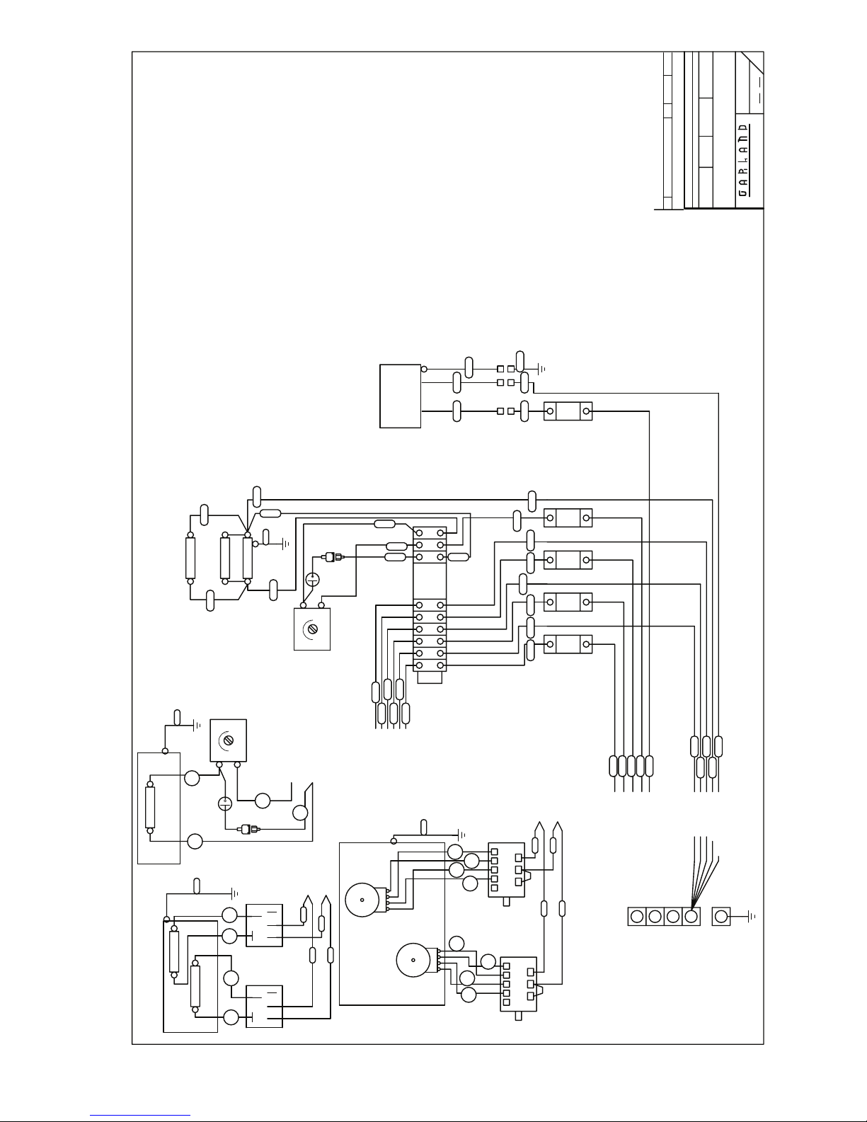
WIRING DIAGRAM S/SS686RC
COMMERCIAL RANGES LIMITED
MISSISSAUGA, ONTARIO, CANADA
TITLE:
BROWN
TB1-9c
3.35kW
HOT TOP / (OPEN TOP)
3.35kW TOTAL /(8"=2.1kW, 6"=1.25kW)
GREEN/YELLOW
M~
BLUE
E4
GRIDDLE
1675W
G4
G2
E3
1675W
S(8)
S(5)
S(7)S(6)
ER 7kW
SALAMANDER
E5a
O2(4)
5kW TOTAL
3-1a
0
40°-230°C
6
4
2.5kW
TB1-10e
GRIDDLE THERMOSTAT
H1
H2
H1
H2
TB1-10a
E1a
OVEN
TB1-12a
3
4
RL2
1
5
TB1-9b
G3
P
L2
OVEN THERMOSTAT
TB1-10b
COOK OFF COOL
L (RED)
G1
OT4
SWITCH
N (BLACK)
N (BLACK)
OT2
65°-290°C
OT3
0-6a
L1 (RED)
OT1
TOP
TB1-10c
TB1-12b
TB1-11b
TB1-10d
TB1-10b
TB1-8c
TB1-6
TB1-5
N
TOP 3
3421
12
TB1-11a
TB1-10c
TB1-9b
TB1-8b
TB1-7b
TB1-2
TB1-4
TB1-1
TB1-3
LNLNL
TOP 1
TOP 2
TB1-10a
TB1-9a
TB1-8a
TB1-7a
1 2 3 4 5 6 7 8 9 10 11
TB1
E2
4
3
1
2
3
3421
1
P L1
L1
L2
SEALED ELEMENT
2.6kW, 220mm
2.0kW, 180mm
2
TB1-10f
2.5kW
TB1-10g
TB1-12c
1
RL1
H1 H2
H2H1
S(3) S(4)
TB1-9c
SALAMANDER
O1(4)
1
232
H146
29"
GRN
NO
1
3
40A_0A_0A_0A 40A
2
0
1
NC
WHT
DOOR SWITCH LEFT
BLK
COM
O1(3)
T3(4)T3(3)
T2(4)
_0A _0A 40A 40A
_0A
T1(3) T1(4) T2(3)
TOP 1 TOP 2 TOP 3 OVEN
4600W TOPS = 30A
3350W TOPS = 20A
T1(2)
T3(2)
S(2)
T1(1)
T2(1)
T3(1)
O1(1)
S(1)
L (RED)
N (BLACK)
ST4
P2
P1
P3
6 HEAT SWITCH
ST3
ST1
ST2
P2
P1
P3
SEE TERMINAL BLOCK CONNECTIONS
43125
6 HEAT SWITCH
4
43125
TOP 3 RED
TOP 2 RED
TOP 1 RED
OVEN 1 RED
SALAMANDER RED
X
Y
3 PHASE
SHEET 2
RED
RED
RED
RED
RED
S(1)
O1(1)
T3(1)
T2(1)
T1(1)
X
Y
1 PHASE
T2(2)
O1(2)
TOP 3 BLACK
TOP 2 BLACK
TOP 1 BLACK
OVEN 1 BLACK
SALAMANDER BLACK
Z
Z
BLACK
T1(2)
T2(2)
BLACK
BLACK
T3(2)
BLACK
O1(2)
G
BLACK
S(2)
G
Part # P152 Rev 1 (01/13/10)Page 22
 Loading...