

Garland SU680 Series, SS680 Series, S684, SU684, SU684RC2 Installation, Operating And Service Instructions
...Page 1
INSTALLATION, OPERATING
& SERVICE INSTRUCTIONS
FOR THE GARLAND
S680, SS680 & SU680 SERIES RESTAURANT
RANGES AND SALAMANDERS
WARNING:
FOR YOUR SAFETY
DO NOT STORE OR USE GASOLINE OR OTHER
FLAMMABLE VAPORS OR LIQUIDS IN THE
VICINITY OF THIS OR ANY OTHER APPLIANCE.
PLEASE READ ALL SECTIONS OF THIS MANUAL AND RETAIN FOR FUTURE REFERENCE.
IMPROPER INSTALLATION, ADJUSTMENT,
ALTERATION, SERVICE OR MAINTENANCE CAN
CAUSE PROPERTY DAMAGE, INJURY OR DEATH.
READ THE INSTALLATION, OPERATION AND
MAINTENANCE INSTRUCTIONS THOROUGHLY
BEFORE INSTALLING OR SERVICING
THIS EQUIPMENT.
THIS PRODUCT HAS BEEN CERTIFIED AS COMMERCIAL COOKING EQUIPMENT AND MUST BE INSTALLED
BY PROFESSIONAL PERSONNEL AS SPECIFIED.
For Your Safety Post in a prominent location,.
Users are cautioned that maintenance and repairs must be performed by a Garland authorized service agent using genuine
Garland replacement parts. Garland will have no obligation with respect to any product that has been improperly installed,
adjusted, operated or not maintained in accordance with national and local codes or installation instructions provided
with the product, or any product that has its serial number defaced, obliterated or removed, or which has been modified
or repaired using unauthorized parts or by unauthorized service agents. For a list of authorized service agents, please refer
to the Garland web site at http://www.garland-group.com. e information contained herein, (including design and parts
specifications), may be superseded and is subject to change without notice.
Continuous product improvement is a Garland policy, therefore design and specifications are subject to change without notice.
GARLAND COMMERCIAL INDUSTRIES
185 East South Street
Freeland, Pennsylvania 18224
Phone: (570) 636-1000
Fax: (570) 636-3903
Part # P153 (11/06) Page 1
Part # P153 (11/06) © 2004 Garland Commercial Industries, Inc.
GARLAND COMMERCIAL RANGES,
LTD.
1177 Kamato Road, Mississauga, Ontario L4W 1X4
CANADA
Phone: 905-624-0260
Fax: 905-624-5669
Enodis UK LTD.
Swallowfield Way, Hayes, Middlesex UB3 1DQ ENGLAND
Telephone: 081-561-0433
Fax: 081-848-0041
Page 2

IMPORTANT INFORMATION
WARNING:
is product contains chemicals known to the State of California to cause cancer. Installation and servicing of
this product could expose you to airborne particles of glass wool/ceramic fibers. Inhalation of airborne particles
of glass wool/ceramic fibers is known to the State of California to causes cancer.
Part # P153 (11/06)Page 2
Page 3

TABLE OF CONTENTS
Important Information. . . . . . . . . . . . . . . . . . . . . . 2
Dimensions And Specifications,
Models S,SU& SS684 . . . . . . . . . . . . . . . . . . . . . . 4
Dimensions And Specifications,
Models S,SU& SS686 . . . . . . . . . . . . . . . . . . . . . . 5
Dimensions And Specifications, Range Models . . . 6
Dimensions And Specifications,
Models SERC, SER-680. . . . . . . . . . . . . . . . . . . . . 7
Introduction . . . . . . . . . . . . . . . . . . . . . . . . . . . . . . 8
Uncrating . . . . . . . . . . . . . . . . . . . . . . . . . . . . . . . . . . . . . .8
Rating Plate . . . . . . . . . . . . . . . . . . . . . . . . . . . . . . . . . . . .8
Safety Precautions . . . . . . . . . . . . . . . . . . . . . . . . . . . . . . .8
Installation . . . . . . . . . . . . . . . . . . . . . . . . . . . . . . . 9
Clearances . . . . . . . . . . . . . . . . . . . . . . . . . . . . . . . . . . . . .9
Siting . . . . . . . . . . . . . . . . . . . . . . . . . . . . . . . . . . . . . . . . .9
Legs . . . . . . . . . . . . . . . . . . . . . . . . . . . . . . . . . . . . . . . . . .9
Casters . . . . . . . . . . . . . . . . . . . . . . . . . . . . . . . . . . . . . . . .9
Ventilation Air . . . . . . . . . . . . . . . . . . . . . . . . . . . . . . . . . .9
Installation Of Range Mount Salamander . . . . . . . . . . . .10
Assembly Of Backguard/High Shelf . . . . . . . . . . . . . . . .10
Code Requirements . . . . . . . . . . . . . . . . . . . . . . . . . . . . .10
Electrical Supply . . . . . . . . . . . . . . . . . . . . . . . . . . . . . . .10
Single And ree Phase Connection . . . . . . . . . . . . . . . .10
Commissioning . . . . . . . . . . . . . . . . . . . . . . . . . . . . . . . .10
Product Application . . . . . . . . . . . . . . . . . . . . . . . 14
Griddles . . . . . . . . . . . . . . . . . . . . . . . . . . . . . . . . . . . . . .14
Solid Hot Tops. . . . . . . . . . . . . . . . . . . . . . . . . . . . . . . . .14
Sealed Hotplate (SS/SU Models) . . . . . . . . . . . . . . . . . . .14
Standard Ovens . . . . . . . . . . . . . . . . . . . . . . . . . . . . . . . .14
RC Convection Ovens . . . . . . . . . . . . . . . . . . . . . . . . . . .15
Maintenance And Cleaning . . . . . . . . . . . . . . . . . 15
General . . . . . . . . . . . . . . . . . . . . . . . . . . . . . . . . . . . . . . 15
Cleaning
Stainless Steel . . . . . . . . . . . . . . . . . . . . . . . . . . . . . . . . . . 15
Enameled Surfaces . . . . . . . . . . . . . . . . . . . . . . . . . . . . .15
Salamander . . . . . . . . . . . . . . . . . . . . . . . . . . . . . . . . . . .16
Ovens . . . . . . . . . . . . . . . . . . . . . . . . . . . . . . . . . . . . . . . .16
Griddles
After Each Use . . . . . . . . . . . . . . . . . . . . . . . . . . . . . . . . .16
For Heavy Build Up. . . . . . . . . . . . . . . . . . . . . . . . . . . . .16
Griddle Do’s & Don’ts . . . . . . . . . . . . . . . . . . . . . . . . . . .16
ermostat Calibration
Oven . . . . . . . . . . . . . . . . . . . . . . . . . . . . . . . . . . . . . . . .17
Griddle. . . . . . . . . . . . . . . . . . . . . . . . . . . . . . . . . . . . . . .17
Safety . . . . . . . . . . . . . . . . . . . . . . . . . . . . . . . . . . 18
Initial Operation . . . . . . . . . . . . . . . . . . . . . . . . . 11
Preparing A New Griddle. . . . . . . . . . . . . . . . . . . . . . . . .11
Seasoning Of e Griddle . . . . . . . . . . . . . . . . . . . . . . . .11
Operating Instructions. . . . . . . . . . . . . . . . . . . . . 11
Operation Of e Griddle: . . . . . . . . . . . . . . . . . . . . . . .11
Operating e Solid Hot Top . . . . . . . . . . . . . . . . . . . . .11
Operating e Sealed Hotplate (SS/SU) Models . . . . . . .12
Operation Of Standard Ovens . . . . . . . . . . . . . . . . . . . . .12
Operation Of e Convection Ovens . . . . . . . . . . . . . . .13
Operation Of e Salamander. . . . . . . . . . . . . . . . . . . . .13
Part # P153 (11/06) Page 3
Page 4
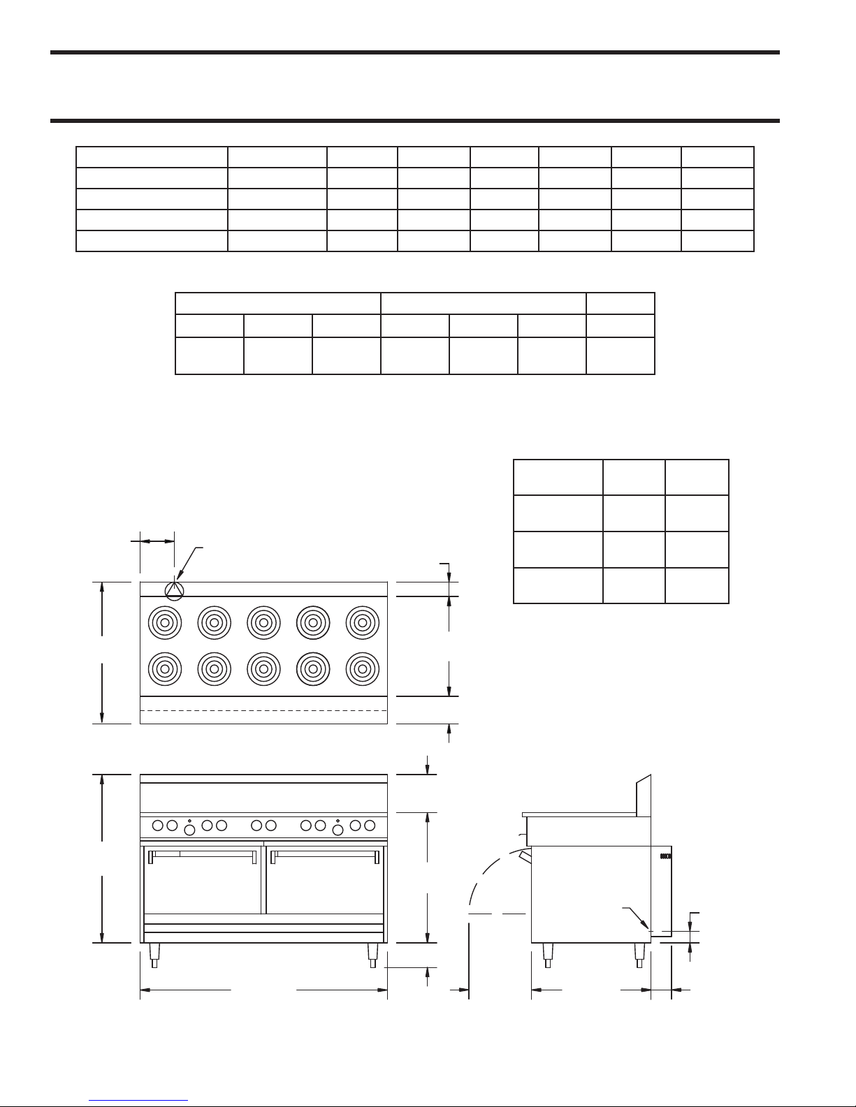
DIMENSIONS AND SPECIFICATIONS, MODELS S,SU & SS684
7-1/2"
[190mm]
REAR CABLE
ENTRANCE
3-1/2"
[829mm]
24-1/2"
[622mm]
34-1/4"
[870mm]
41"
[1041mm]
9-1/4"
[235mm]
31-3/4"
[806mm]
6"
[152mm]
60"
[1524mm]
REAR CABLE
ENTRANCE
15-1/4"
[387mm]
29"
[737mm]
3"
[76mm]
4-3/4"
[mm]
W/OPTIONAL
RC MOTOR
6"
[152mm]
Model Total Kw Load 208V/1Ph 208V/3 Ph 240V/1Ph 240V/3 Ph 400 V/3N 415V/3N
S684*
SU684**
SU684RC2***
Salamander Broiler**** 7 34 23 29 20 4 4
*(all purpose tubular elements) **(Sealed -top elements, North American Model # SS684) *** Maximum on any 684 series range.
****Add when wired to range base (SER /SUER-680)
Exterior Dimensions Oven Interior Dimensions Weight
Height Width Depth Height Width Depth Lbs/Kg
47”
(1194mm)
Ratings:
Tubular Elements - Small 6-1/2” (165mm) - 1250 Watts. Large 8-1/2” (216mm) - 2100 Watts
Sealed High Performance Elements - Small 7” (180mm) - 2000 Watts. Large 8-5/8” (220mm) - 2600 Watts
Hot Top (per 12”/305mm section) - Front and Rear sections each 1675 Watts, (3350 Watts total)
Griddle (per 12”/305mm section) - 3350 Watts
Standard Oven - 4.85 kW
Convection Oven - 5.0 kW (plus 0.5kW fan motor, for 5.5kW total)
27 127 76 110 66 — —
33 157 97 136 84 60 58
34 N/A 100 142 87 60 58
60”
(1524mm)
31-1/4”
(794mm)
13-1/2”
(343mm)
26-1/4”
(667mm)
22”
(559mm)
Installation
Clearances:
Range w/o
Salamander
Range w/
Salamander
Hot Sections
600/273
Side Back
3”
(76mm)
7”
(178mm)
10”
(254mm)
2”
(51mm)
2”
(51mm)
—
NOTE: For ranges with convection oven(s), (models
with suffix `RC’ or `RC2’), air circulation is required
for proper operation of fan motors. ese models must
not be dais mounted or installed without legs.
NOTE: Salamander can not be installed wired from
the range base on a S684 in 208/1/60. Salamander must
have a separate circuit.
NOTE: Many local codes exist, and it is the respon-
sibility of the Owner and the Installer to comply with
those codes.
Part # P153 (11/06)Page 4
Page 5
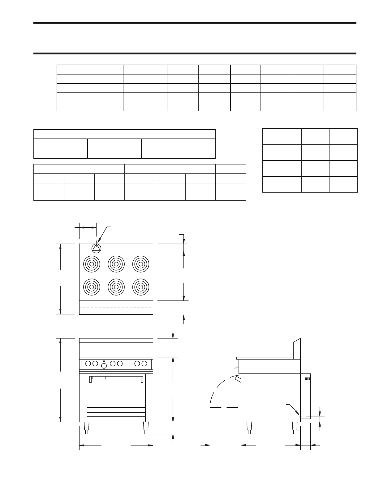
DIMENSIONS AND SPECIFICATIONS, MODELS S,SU & SS686
8-3/8"
[213mm]
34-1/4"
[870 mm]
3-1/2"
[89mm]
24-1/2"
[622mm]
REAR CABLE
ENTRANCE
41"
[1041mm]
9-1/4"
[235mm]
31-3/4"
[806mm]
6"
[152mm]
36"
[914mm]
15-1/4"
[387mm]
29"
[737mm]
3"
[76mm]
4-3/4"
[121mm]
W/OPTIONAL
RC MOTOR
REAR CABLE
ENTRANCE
6"
[152mm]
Model Total Kw Load 208V/1Ph 208V/3 Ph 240V/1Ph 240V/3 Ph 400 V/3N 415V/3N
S686*
SU686**
SU686RC2***
Salamander Broiler**** 7 34 19 29 16 4 4
*(All purpose tubular elements) **(Sealed -top elements, North American Model # SS686) *** Maximum on any 684 series range.
****Add when wired to range base (SER /SUER-680)
15 72 48 62 42 — —
19 90 59 78 52 40 38
20 93 62 80 54 40 38
Entry Clearances
Crated Uncrated Uncrated “RC” Model
45” (1143mm) 35” (889mm) 40” (1016mm)
Exterior Dimensions Oven Interior Dimensions Weight
Height Width Depth Height Width Depth Lbs/ Kg
47”
(1194mm)
36”
(914mm)
31-1/4”
(794mm)
13-1/2”
(343mm)
26-1/4”
(667mm)
22”
(559mm)
360/190
Ratings:
Tubular Elements: 6-1/2” (165mm): 1250 Watts
Sealed High Performance Elements: 7” (180mm): 2000 Watts
Hot Top (per 12”/305mm section):
Griddle (per 12”/305mm section): 3350 Watts
Standard Oven: 4.85 kW
Convection Oven: 5.0 kW (+0.5kW fan motor; for 5.5kW total)
NOTE: For ranges with convection oven(s), (models with suffix `RC’
or `RC2’), air circulation is required for proper operation of fan motors.
ese models must not be dais mounted or installed without legs.
NOTE: Many local codes exist, and it is the responsibility of the
Owner and the Installer to comply with those codes.
Installation
Clearances:
Range w/o
Salamander
Range w/
Salamander
Hot Sections
Side Back
3”
(76mm)
(51mm)
7”
(178mm)
(51mm)
10”
(254mm)
8-1/2” (216mm): 2100 Watts
8-5/8” (220mm): 2600 Watts
Front and Rear sections each 1675 Watts,
(3350 Watts total)
2”
2”
—
Part # P153 (11/06) Page 5
Page 6

S/SS/SU 686/684 RC (2) -(1,2,3) (L,C,R) -(12,24,36) (L,C,R)
-12 = 12" (305 mm) wide griddle
-24 = 24" (610 mm) wide griddle
-36 = 36" (915 mm) wide griddle
- L = griddle on left hand side of range
- C = griddle in center of range
- R = griddle on right hand side of range
-1 = 12" (305mm) wide solid top
-2 = 24" (610mm) wide solid top
-3 = 36" (915mm) wide solid top
-L = Solid top on left hand side of range
-C = Solid top in center of range
-R = Solid top on right hand side of range
RC = Convection Oven
RC2 = Double convention oven base
686 = 36" (915mm) wide range
684 = 60" (1524mm) wide range
S = Sentry series range
SU = Sentry series range
CE marked design
SS = Sentry series range
with sealed top elements
DIMENSIONS AND SPECIFICATIONS, RANGE MODELS
Part # P153 (11/06)Page 6
Page 7
3"
[76mm]
REAR CABLE
ENTRANCE
34"
[864mm]
16-14"
[413mm]
1-1/8"
[29mm]
18"
[457mm]
34-1/4"
[870mm]
20-1/4"
[514mm]
36"
[914mm]
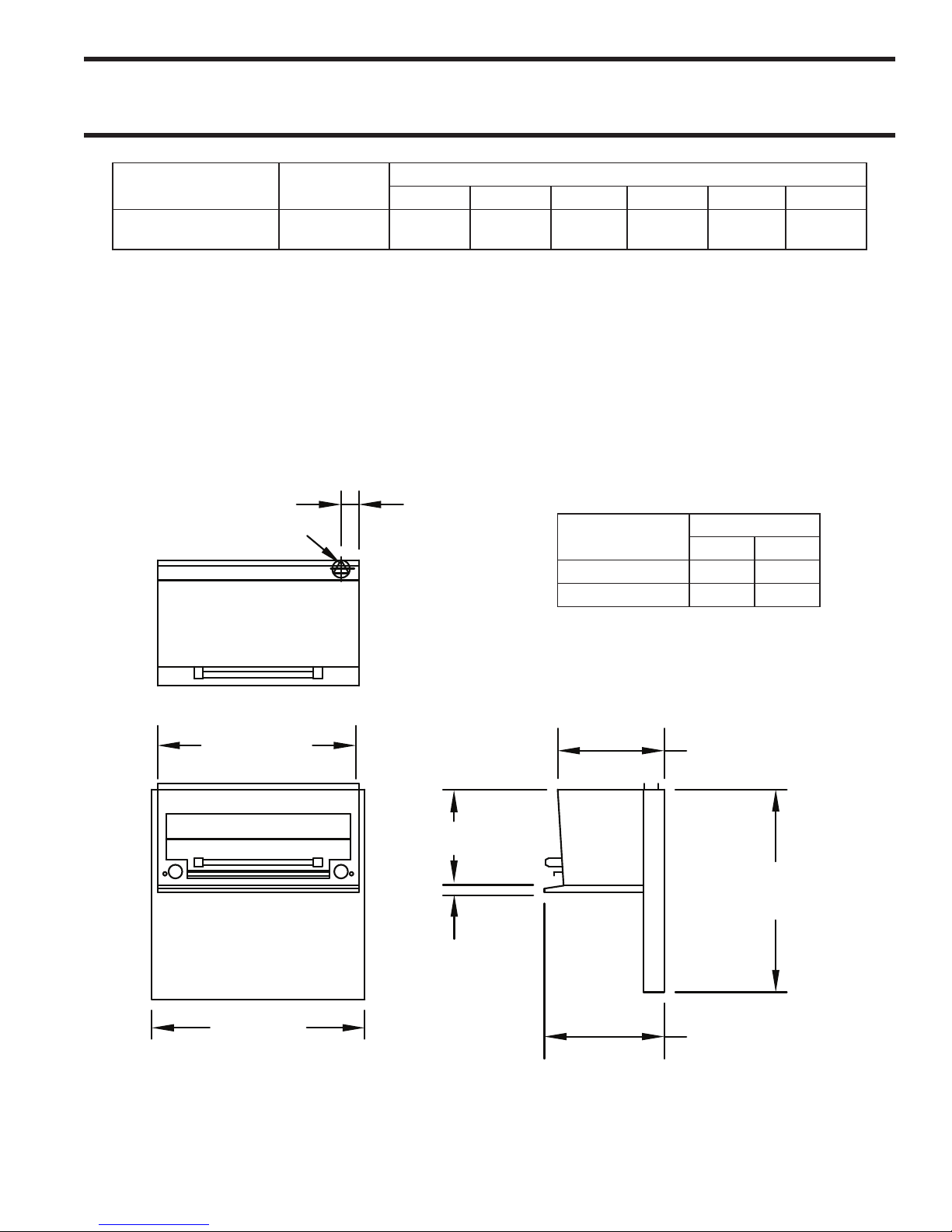
DIMENSIONS AND SPECIFICATIONS, MODELS SERC, SER-680
Model Total Kw Load
SERC, SER-680
wired independently
208V/1Ph 208V/3 Ph 240V/1Ph 240V/3 Ph 400 V/3N 415V/3N
7 34 29 29 25 15 15
TOTAL AMPS
Installation Notes:
Clearances from combustible surfaces should be minimum 7” (178mm) from sides, 2” (51mm) from back
Note: Salamander can not be installed wired from the range base on a S684 in 208/1/60. Salamander must have
a separate circuit.
KW Ratings
Total kW loading is 7.0 kW
Model
S/SUERC 164 76
S/SUER-680 190 86
Weight
Pounds KG
Part # P153 (11/06) Page 7
Page 8

INTRODUCTION
is appliance should be given regular care and
maintenance. Periodic inspections by your dealer or a
qualified service agency are recommended.
NOTE: Many parts of the equipment are raw steel, i.e..,
griddle top and solid hot top and can react with moisture
forming rust. is is normal and not considered a defect.
A light coating of salt free oil may be applied to prevent
further rusting.
Uncrating
1. Check the crate for possible damage sustained
during transit. Carefully remove the unit from the
crate and again check for damage. Any damage
to the appliance must be reported to the carrier
immediately.
2. All packing material must be removed from the
unit. e protective material covering the stainless
steel must be removed immediately, after the unit is
installed.
Safety Precautions
is manual pertains to ranges and salamanders. e
reader/operator must interpret its contents to applicable
needs. If there is any question of interpretation of
any of the literature pertaining to Garland ranges or
salamanders, please contact your authorized service
agency, or our customer service department at the phone
number listed on the front of this manual or on our web
site: http://www.garland-group.com.
A qualified person must make the installation of these
products in accordance with the local codes of the
country of destination.
Always follow these safety precautions when operating
the range or salamander.
1. e Unit must only be operated by qualified persons.
DO NOT operate without reading this manual.
2. DO NOT operate the product unless it has been
properly installed and grounded.
3. All ranges are shipped from the factory with legs or
casters fitted unless specially ordered without.
4. e splash back and high shelf is packed and ordered
separately.
5. Do not remove permanently affixed labels, warnings
or data plates from the appliance, for this may void
approvals and create a safety hazard.
Rating Plate
e data plate is readily accessible, located behind
the lower panel on ranges & behind the drip tray on
salamanders. It contains all the pertinent information
required by the installer.
When corresponding with the factory or your local
authorized factory service center regarding service
problems or replacement parts, be sure to refer to the
particular unit by the correct model number (including
the prefix and suffix letters and numbers) and the
warranty serial number. e rating plate affixed to the
unit contains this information.
3. DO NOT operate the product unless all service and
access panels are in place and fastened properly.
4 DO NOT attempt to repair or replace any part of
this product unless all main power supplies have
been disconnected.
WARNING: to avoid personal injury: Use Extreme
caution in setting up, operating and cleaning the product
to avoid coming in contact with the hot grill surfaces or
hot grease. Suitable protective clothing should be worn
to prevent the risk of burns.
NOTE Other Safety precautions are noted throughout
this manual, when applicable for specific operations.
Part # P153 (11/06)Page 8
Page 9

INSTALLATION
is equipment must be installed by a competent factory
trained, certified, licensed and / or authorized service
or installation person. Electrical work must be installed
by a qualified person as required by the local electrical
authorities.
WARNING: is appliance must be grounded.
CAUTION: Prior to installation check the electrical
supply to ensure the input voltage and phase match the
equipment voltage rating and phase as shown on the
rating plate.
Clearances
e space in which the appliance is to be positioned
must include the minimum installation clearances to
combustible surfaces
MINIMUM INSTALLATION CLEARANCES
Clearance To Combustible Material
Models
Location
Top * * *
Sides 3” (76mm) 10” (254mm) 7” (178mm)
Rear 2” (51mm) 2” (51mm) 2” (51mm)
Ranges
* NOTE: Garland recommends equipment be installed
under a ventilation canopy
LOCATION
Models Type Of Floor Or Base
Ranges Combustible
Ranges c/w Hot Top Combustible
Salamander Non-Combustible
IMPORTANT: For ranges with convention oven
(models with suffix “RC”), air circulation is required
for proper operation of the fan motors. Allow ” (mm)
rear clearance for ventilation of the motor.
Adequate clearance must be provided for servicing,
ventilation and proper operation. e range must be
kept clear of combustible material.
Ranges
c/w Hot Top
Salamander
Positioning
e range should be installed on a firm, smooth and
level floor designed to withstand the weight of the fully
laden appliance.
Place the range or salamander in desired position and
level from side to side and back to front and diagonally.
is leveling must be done with the unit under the hood
and in it’s normal operating position. If the range is to
be dais or cove mounted, the base on which it is to be set
should be level. If it is not, the range must be shimmed
to level.
Legs
All ranges are shipped from the factory with legs installed
unless otherwise specified. When the range is specified
for dais or cove base mounting, it is shipped less legs. Legs
must be adjusted to a minimum height of ” (mm)
in order to comply with NSF standards.
Casters
1. e front casters on the unit are equipped with
brakes to limit the movement of the range without
depending on the electrical connection to limit
appliance movement.
2. A restraint can be attached to the unit near the
electric connection. If the restraint is disconnected,
be sure to reconnect it after the range has been
returned to its originally installed position.
Ventilation Air
e area in which the appliance is installed must be
adequately ventilated to provide air for removal of steam,
heat generated by the appliance, etc. ese products
are recommended to be installed under a ventilation
hood.
Proper operation of exhaust fans (proper speed, rotation
and adjustment) is essential. e hood, and the filters
must be cleaned on a regular bases and kept grease
free.
Part # P153 (11/06) Page 9
Page 10

INSTALLATION Continued
Installation Of Range Mount Salamander
1. e rear of the range must be easily accessible.
2. Place the salamander in position on the range.
Slide the uprights into the opening at the oven rear.
Secure the salamander uprights to the range with
the hex head bolts provided.
3. Remove the terminal block access cover
4. Pass the wires though cable entrance hole.
5. Secure the cable connector
6. Terminate the salamander wire at the terminal
block provided (Red to L1, Black to L2 or N, Green
to GRN or E).
NOTE: When mounting a salamander over an existing
range in the field, an independent fussed connection
must be made though the knock out plate provided in
the main back of the salamander.
Assembly of Backguard/High Shelf
e back guard or high shelf will have been shipped
separately. To install, put the backguard/high self on the
rear of the range, slipping the uprights into the opening
on each burner box side. Fasten the upright to the burner
box side with four hex fasteners provided.
Code Requirements
Electrical Supply
Before attempting the electrical connection, the
rating plate should be checked to ensure that the
equipment’s electrical characteristics and supply electrical
characteristics agree. On ranges and salamanders the
supply entrance is located at the rear or alternatively on
the main bottom. e supply terminal block is accessible
from the front. e electrical supply must be adequate
for the voltage, phase, and current marked on the rating
plate.
NOTE: A means of disconnection from the supply
having a contact separation of at least mm in all poles
must be incorporated in the fixed wiring.
is equipment is intended to be installed with fixed
permanent wiring.
WARNING: is appliance must be grounded.
Single And ree Phase Connection
Unless otherwise noted, all ranges are shipped from the
factory for three phase connection. Salamanders are
shipped from the factory for single phase connection. A
wiring diagram is attached to the rear of each appliance.
Visually check all electrical connections. e range is
wired at the factory as specified on the order. If it is
necessary to change the phasing refer to the wiring
diagram.
e Garland S/SS series complies with the standards
CSA C. no. – latest edition, the UL – latest
edition and the NSF# – latest edition. e installation
and connection of this appliance must comply with
current codes. In Canada – e Canadian Electrical
Code Part and in the USA – e National Electrical
Code.
e Garland SU series complies with the essential
requirements of the Directives //EEC, //EEC,
//EEC, //EEC and the standards, EN,
IEC., IEC., IEC., IEC., IEC. and
IEC..
Commissioning
Ensure all circuit breakers located in the lower
compartment are set to the ON () position
1. Ensure that all controls are in the OFF position and
turn on the main electrical supply
2. Operate each section of the range or salamander
in accordance with the instructions given in the
Operating Instructions
3. Check that the product functions correctly and
that the voltage supply to the unit does not drop
more than 5% when all sections are operated
simultaneously.
Part # P153 (11/06)Page 10
Page 11
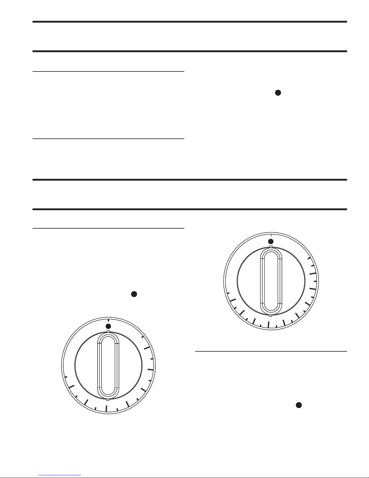
INITIAL OPERATION
4
5
0
4
0
0
3
5
0
3
0
0
2
5
0
2
0
0
1
5
0
1
0
0
2
1
3
8
8
0
0
˚
F
2
2
0
2
0
0
1
8
0
1
6
0
1
5
0
1
2
0
1
0
0
8
0
3
0
4
0
2
1
3
8
8
0
1
˚
C
2
3
0
Preparing a New Griddle
1. Remove the protective coating on the surface using
mild detergent
2. oroughly rinse the griddle with vinegar and a
water solution (3/4-cup vinegar per quart of water)
and dry.
Seasoning of the Griddle
1. Using a clean cloth, rub a thin and even layer of
oil into the griddle surface. Oil should be unsalted
shortening or high temperature cooking oil.
OPERATING INSTRUCTIONS
Operation of the Griddle:
e griddle must be seasoned before initial operation.
2. Set the griddle thermostat to 130°F (55°C) and heat
griddle surface until the oil begins to caramelize
(turn a golden brown color). Once this occurs, turn
the thermostat to OFF “ ”
3. Scrape off the caramelized oil with a standard
spatula.
4. Repeat step 1, and set the griddle thermostat to
275°F (135°C)
5. Repeat steps 2 & 3. e griddle is now seasoned
and ready for use.
Griddle Operating Control Centigrade
NOTE: Ensure the electrical supply to the appliance
is turned on.
1. Set the thermostat to the desired temperature.
Shutting the griddle down:
1. Set the thermostat to the OFF ( ) position.
Griddle Operating Control Fahrenheit
Operating e Solid Hot Top
1. Set the control dial to the desired position from
MIN - 2,3,4,5,6, - MAX
2. e recommended pre-heat time is minutes
Part # P153 (11/06) Page 11
Shutting e Solid Hot Top Down
1. Set the control dial to the OFF ( ) Position.
Page 12
M
A
X
M
I
N
2
3
4
5
6
2
1
3
9
0
0
0
OPERATING INSTRUCTIONS Continued
1
2
3
4
5
6
2
1
3
9
1
0
0
5
5
0
5
0
0
4
5
0
4
0
0
3
5
0
3
0
0
2
5
0
2
0
0
1
5
0
2
6
8
5
9
0
0
˚
F
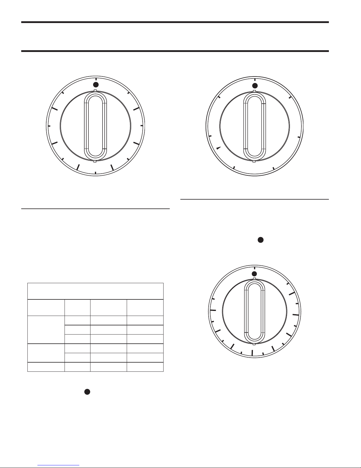
Solid Top/Open Top (Tubular) Operating Controls
Operating e Sealed Hotplate
(SS/SU) Models
1. Before using sealed hotplates for the first time they
should be heated at setting 3 for five (5) minutes.
is will harden and burn off the protective
coating.
2. Set the six heat switch dial to the desired position
for 1 to 6.
Sealed Hot Plate Operating Controls
Operation Of Standard Ovens
1. Set dial to desired temperature, preheat for at least
45 minutes after turning on the oven from cold.
Shutting down oven:
1. Set the dial to the OFF ( ) Position.
Oven Operating Controls Fahrenheit
3. Do not preheat.
SEALED HOT PLATE WATTAGES AND
APPLICATIONS
Dial
Setting
6 2600 W 2000 W
5 1750 W 1400 W
4 1300 W 950 W
3 450 W 450 W
2 340 W 305 W
Application
Broiling,
Frying,
Braising
Simmering
Warming 1 240 W 200 W
Shutting Down e Sealed Hot Plate:
. Set dial to the OFF ( ) position
8 2/3”
(220mm)
7”
(180mm)
Part # P153 (11/06)Page 12
Page 13
2
9
0
2
6
0
2
3
0
2
0
5
1
7
5
1
5
0
1
2
0
9
5
6
5
2
6
8
5
9
0
1
C
˚
OPERATING INSTRUCTIONS Continued
1
2
3
2
6
9
3
0
0
0
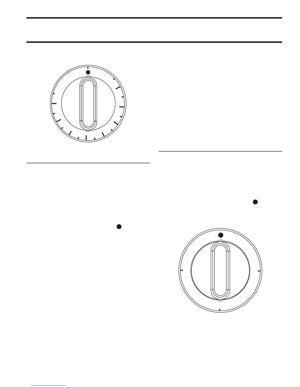
Oven Operating Controls Centigrade
Operation of the Convection Ovens
Starting the Oven:
1. Set the cook/cook switch to the “Heat” position
2. Set ermostat to the desired temperature
3. Preheat the oven thoroughly before use (at least 30
minutes).
Shutting down:
1. Set the thermostat dial to the OFF ( ) position.
B. Since the blower wheel is in the oven cavity it is at
the same temperature as the oven. If the motor is
stopped while the oven is hot, the heat from the
blower wheel is conducted down the shaft and
into the armature of the motor. is action could
shorten the motor life.
C. We recommend, at the end of the bake or roasting
period or before shutting down completely, that
the doors be left open. Set the fan switch to the
“COOL DOWN” position. e fan should run for
at least 20 minutes. e “FAN” should never be
turned “OFF” when the oven is “HOT”.
Operation of the Salamander
1. Set the three heat switch to the desired position
from – 1 (MIN), 2, 3 (MAX).
2. Allow the salamander to preheat before adding
product
Shutting the salamander down
1 Set the three heat switch to the OFF ( ) position.
2. Turn the switches to the off position when the unit
is not in use.
2. Open door
3. Activate power to the cool down
e motor on your range convection oven is maintenance
free since it is constructed with self-lubricating sealed ball
bearings. It is designed to provide durable service when
treated with ordinary care. We have a few suggestions
to follow on the care of your motor.
A. When the motor is operating, it cools itself internally
by air entering the rear of the motor case, provided
proper clearance has been allowed.
Part # P153 (11/06) Page 13
Page 14

PRODUCT APPLICATION
e top of the range is designed for flexibility and the
preparation of numerous types of products.
Griddles
Griddle tops are designed to have food cooked directly
on the surface. Do not put pots or pans on the griddle
surface as this will scratch or nick the surface and will
result in improper cooking or sticking of the product.
Never salt food over the griddle since this will build up
gummy residue making it difficult to clean.
Avoid hitting the surface of the griddle with the edge of a
spatula, since this will cause nicks. e most frequently used
temperatures are ° F to ° F (° C to ° C). After
one firing, the griddle plate will discolor. is is normal and
will not affect cooking performance.
Solid Hot Tops
Recommended where long term stock pot cooking is
required for soups, sauces, or stocks. Pots can be placed
anywhere on the hot top. e maximum recommended
stock pot size is ” (mm) diameter.
e recommended pre-heat time is minutes. is
will thoroughly saturate the plate. Pots must have flat
bottoms for maximum contact with the hot surface.
Roasting pans with straps should never be used on a
hot top since only the straps touch the surface and heat
transfer will be minimal.
Preparation of soups, stocks, or sauces are done on the
hot top where slow even cooking is desirable. Heating
larger quantities of food can be done more efficiently than
heating small quantities. Pots and pans should be covered
whenever possible to reduce the energy consumption.
High acid sauces, such as tomato should be cooked in
stainless steel vessels rather than aluminum since stainless
steel will not react chemically. Light colored sauces may
be discolored by the aluminum especially if stirred with
a metal spoon. Salty water may pit aluminum if used
frequently.
Sealed Hotplate (SS/SU Models)
All-purpose sealed top elements provide and easy-clean
top. ey are intended for broiling, sauté, and other
range top cooking.
Operation practices are very important for efficient use
of these elements:
1. Pot bottoms must be flat. is increases the heat
transfer to the pot. Do not use pots with convex
bottoms or concave bottoms with more than 1/32”
(1mm) concave.
2. Use pots with the same diameter as the element
where possible. is will reduce heatup time.
3. Do not preheat the element. Elements are protected
with a high limit, which will automatically reduce
the element to a lower power. It will increase heatup
time if this occurs.
4. Use a lid on pots when boiling water.
Standard Ovens
e temperature is automatically controlled by the
thermostat so satisfactory cooking can be repeated. For
best performance the following instructions should be
followed:
Grid shelves: ere are three shelf positions. e shelf
position is governed by the size of the product cooked.
Always push the shelf back into the oven until it pops
making contact with the rear of the oven.
Tray size: A cake tray may be used on each shelf. Single
trays or dishes must not be allowed to overhang the shelf
in any direction, since this will adversely affect the heat
circulation.
Loading: Allow at least minutes after turning the
oven on from cold, with the thermostat at the desired
temperature before loading the oven. Put the food in
quickly and close the oven door.
Part # P153 (11/06)Page 14
Page 15

PRODUCT APPLICATION Continued
RC Convection Ovens
e forced air range oven improves heating efficiencies by
circulating the heated air within the cooking chamber.
is reduces the temperature rise time and baking time.
e oven elements are interlocked with the door. When
the fan switch is in the heat position the elements will
only operate when the door is closed. When the fan
switch is in the cool position the fan will only operate
when the door is open.
Operating suggestions for convection ovens:
1. As a general guide, set the oven temperature 2550° F (10-20° C) lower than temperature used in
standard ovens.
2. Cooking times may be 2% to 3% less.
3. Keep a close check on any product being prepared
for the first time. e size of the load, temperature
of the product going in, and moisture content are
major factors that influence necessary cook times
and temperatures
4. Record successful times and temperatures for future
reference.
5. Preheat the oven thoroughly before use (at least 30
minutes).
6 Allow air circulation around the product. Center
pans on oven racks.
7. Never place pans directly on the oven bottom.
8 Do not use a deep pan for shallow cakes, cookies,
etc. as heat circulation across the top of these items
is essential for browning.
9. When rethermalizing frozen products, preheat
oven to 50° F (10°C) higher than the cooking
temperature to compensate for heat loss before and
after loading. Return thermostat to the cooking
temperature after loading.
MAINTENANCE AND CLEANING
General
Grease the door hinges and check for loose fasteners.
Tighten as necessary.
Cleaning
WARNING: this appliance must not be cleaned with
a water jet.
Stainless Steel
Stainless steel should be cleaned using mild detergent, a
soft cloth and hot water. If it is necessary to use a nonmetallic scouring pad, always rub in the direction of the
grain in the metal to prevent scratching. Wash a small
area at a time and rinse the washed area with a clean
sponge dipped into a disinfectant and wipe dry with a
clean soft cloth before it can dry.
Use only stainless steel, wood, or plastic tools to scrape
off heavy deposits of grease or oil. Do not use ordinary
steel scrapers or knives as particles of iron may become
imbedded and rust. NEVER USE STEEL WOOL.
Enameled Surfaces
Establish a regular cleaning schedule. Any spills should
be wiped off immediately. e unit should be allowed
to cool down before cleaning any exterior surfaces.
Wipe exposed cleanable surfaces when cool with mild
detergent and hot water. Stubborn residue spots may
be removed with a scouring pad. Dry thoroughly with
a clean cloth.
Part # P153 (11/06) Page 15
Page 16

MAINTENANCE AND CLEANING Continued
Salamander
1. Clean the salamander racks as soon as possible after
cooking with tomato or vinegar based products,
which have a high acid content. ese foods can
cause pitting of the rack surface.
2. Drain and clean drip tray frequently. Excessive oil
drain off can cause spillover.
Ovens
Clean the oven racks and guides with hot soapy water
and dry thoroughly. Clean the oven interior with oven
cleaner following instructions.
Griddles
After Each Use
1. Using a traditional 2 1/2” – 3” (64mm –76mm)
scraper or spatula, scrape the griddle surface (to
remove food particles and oil residues) towards
the grease trough using even front to back strokes.
Deposit debris into the chute.
2. Pour shortening or oil onto the griddle surface using
straight front to back motion. Clean the griddle
using a griddle stone or grill screen. Always wipe
with the grain of the steel, never sideways.
3. Using a clean cloth, rub a thin and even layer of oil
into the griddle surface.
4. Remove the grease drawer, empty and wash
thoroughly with soap and water. Replace.
2. Apply griddle cleaner evenly over the griddle surface
and let sit as directed. Follow the procedures on the
label of the specific cleaning product.
3. Using a traditional scraper or spatula, slosh around
the griddle cleaner to remove the build up.
4. Scrape the griddle surface towards the grease trough
using even back to front stokes. Repeat step 2 if
necessary.
5. Using mild detergent, clean the surface and rinse
thoroughly with water and vinegar solution. Dry
griddle.
6. Using a clean cloth rub a thin and even layer of oil
into the griddle surface.
7. Re-season the griddle as detailed in initial cleaning.
e griddle is now ready for use.
Griddle Do’s & Don’ts
Do’s
1. Season the griddle. is will prevent food from
sticking and make it easier to keep the surface
clean.
2 Keep the surface clean. Scraping the surface
thorough out production to clear foods and oils
prevents build up and will make it easier to keep
the surface clean.
3. Turn the temperature down during slow periods.
Reducing the temperature or turning sections off
during slow times will conserve energy and prevent
the plate from overheating.
For Heavy Build Up
NOTE: After using cleaners and grease cutters, re-season
the griddle.
Apply to a warm griddle for best results.
1. Using a traditional 2 1/2” – 3” (64mm –76mm)
scraper or spatula scrape the griddle surface (to
remove food particles and oil residues) towards
the grease trough using even front to back strokes.
Deposit debris into the chute.
Don’ts
1. Do not use salt to clean the griddle surface, Salt is
corrosive and can cause pitting of the griddle.
2 Do not allow metal utensils (Spatula, scraper, etc.)
to nick and/or dent the surface of the griddle. e
edges of these utensils are sharp and will create
divots that oil can collect and caramelize with will
cause sticking.
Part # P153 (11/06)Page 16
Page 17
MAINTENANCE AND CLEANING Continued
Dial Shaft
Calibration Screw Head
Calibration
Screw Head
Increase
Decrease
1/4" Turn
3. Do not use the griddle as a hot top. A large pan or
pot will trap heat and can cause the griddle plate to
warp.
4. Do not over heat the griddle to preheat faster.
Preheating only takes 15-20 minutes.
ermostat Calibration
WARNING: Turn off the electrical mains before
commencing any service work.
Oven
It is normal for an electromechanical thermostat to cycle
with a °F - ° F (°C - °C) range when checking
calibration allow the thermostat to cycle a minimum
of two times.
1. Place the thermocouple of the test instrument in
the center of the oven.
2. Turn the oven temperature control dial to 400° F
(205° C). In order to allow the oven temperature to
stabilize, the oven control must be allowed to cycle
twice before taking a test reading.
3. Check the temperature reading just when the control
cycles “OFF” as indicated by the cycling pilot lamp.
If the temperature does not read with in 15° F (8°C)
of the dial setting, recalibrate as follows:
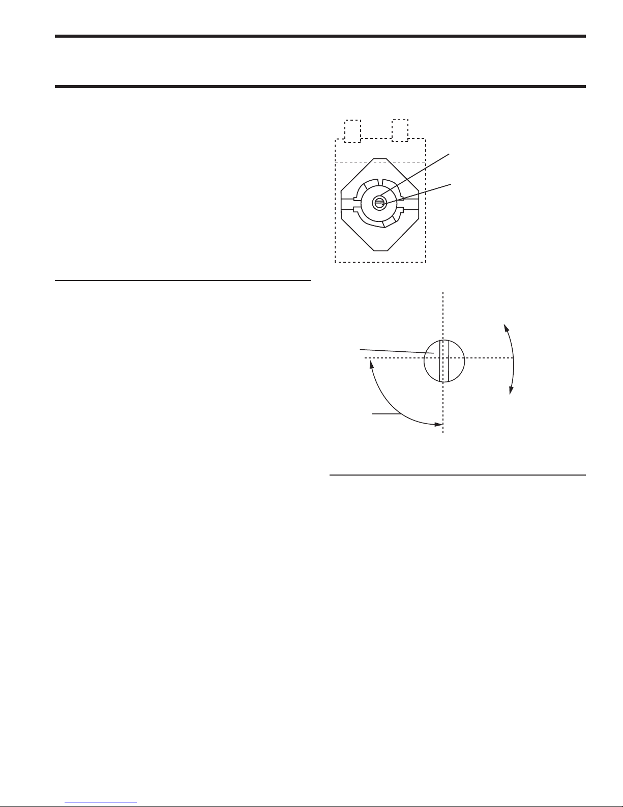
4. Carefully remove the thermostat dial, not disturbing
the dial setting.
5. Hold the thermostat shaft steady with a small
flat blade screw driver. Turn the calibration screw
located inside the shaft clockwise to decrease the
temperature and counter clockwise to increase the
temperature. NOTE: each ¼ turn of the screw will
create a change of approximately 35° F (20°C).
6. Replace the thermostat dial and repeat steps 1
though 3 to verify that the correct adjustment has
been made.
Griddle
1. Use a test instrument with a special disc type
thermocouple or a reliable surface type pyrometer.
NOTE: a drop of oil on the face of the disc will
provide better contact with the plate.
2. Set all griddle thermostats to 350°F (177°C). In
order to allow the griddle temperature to stabilize,
the thermostats must be allowed to cycle twice
before taking a test reading.
3. Check the griddle temperature when the thermostat
just cycles “OFF” by placing the thermocouple
firmly on the griddle directly about the sensing
bulb of the thermostat. e reading should be
between 335° F (168°C) and 365° F and (185°C).
If the reading is outside of these limits, calibrate as
follows:
Part # P153 (11/06) Page 17
Page 18

MAINTENANCE AND CLEANING Continued
4. Carefully remove the dial, not disturbing the shaft
position
5. Hold the shaft steady and with a small flat screw
driver turn the calibration screw located inside
the shaft clockwise to decrease temperature and
SAFETY
It is essential that the instructions in this booklet are
strictly followed for the safe and economical operation
of the equipment. If it is know or suspected that a fault
exists on the appliance then it must not be used until the
fault has been rectified by a competent person.
counter clockwise to increase temperature. NOTE:
Each ¼ turn of the screw will create a change of
approximately 35° F (20°C).
6. Replace the thermostat dial and repeat steps 1
through 3 verify that a correct adjustment has been
made.
Part # P153 (11/06)Page 18
Page 19

NOTES
Part # P153 (11/06) Page 19
Page 20

 Loading...