

Page 1
INSTALLATION AND
SERVICING MANUAL
GARLAND
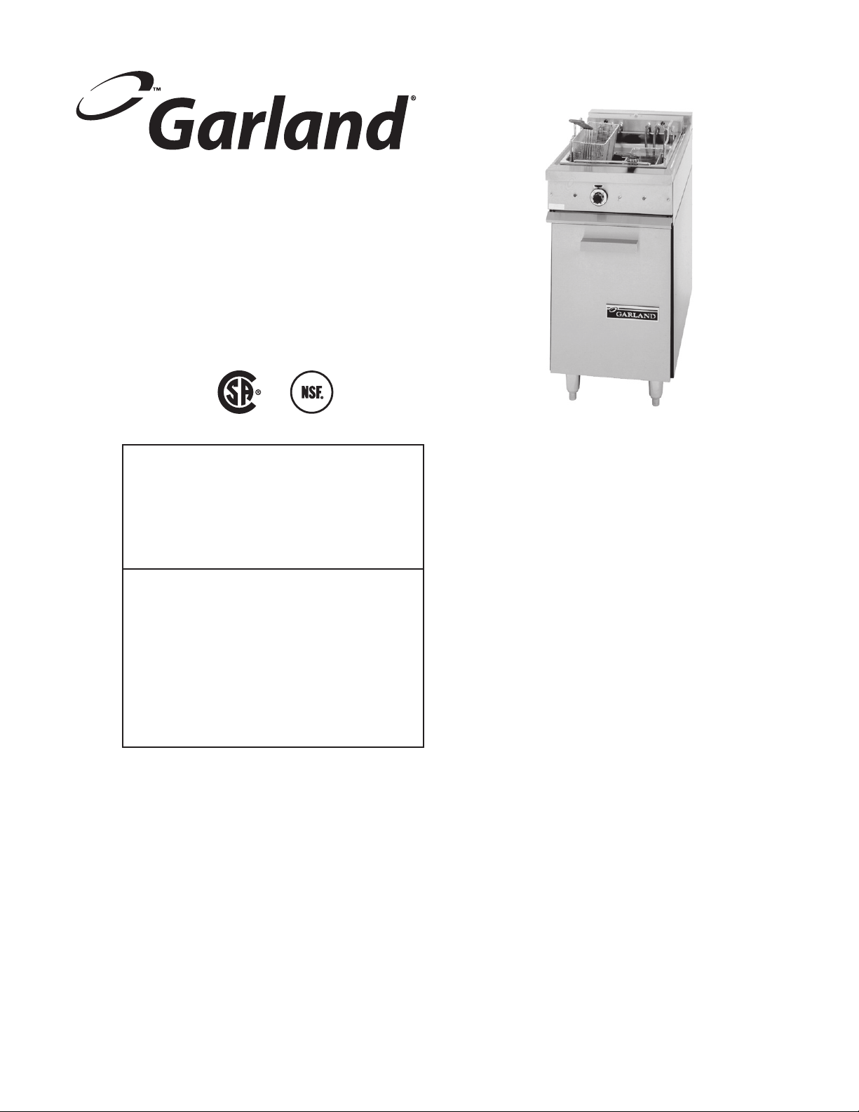
S18-F AND S18-FS SERIES
RESTAURANT FRYERS
NRTL/C
FOR YOUR SAFETY:
DO NOT STORE OR USE GASOLINE
OR OTHER FLAMMABLE VAPORS OR
LIQUIDS IN THE VICINITY OF
THIS OR ANY OTHER
APPLIANCE
PLEASE READ ALL SECTIONS OF THIS MANUAL
AND RETAIN FOR FUTURE REFERENCE.
THIS PRODUCT HAS BEEN CERTIFIED AS
COMMERCIAL COOKING EQUIPMENT AND
MUST BE INSTALLED BY PROFESSIONAL
PERSONNEL AS SPECIFIED.
WARNING:
IMPROPER INSTALLATION, ADJUSTMENT,
ALTERATION, SERVICE OR MAINTENANCE
CAN CAUSE PROPERTY DAMAGE, INJURY,
OR DEATH. READ THE INSTALLATION,
OPERATING AND MAINTENANCE
INSTRUCTIONS THOROUGHLY
BEFORE INSTALLING OR
SERVICING THIS EQUIPMENT
INSTALLATION AND ELECTRICAL CONNECTION
MUST COMPLY WITH CURRENT CODES:
IN CANADA - THE CANADIAN ELECTRICAL
CODE PART 1 AND / OR LOCAL CODES.
IN USA – THE NATIONAL ELECTRICAL CODE
ANSI / NFPA – CURRENT EDITION.
ENSURE ELECTRICAL SUPPLY CONFORMS WITH
ELECTRICAL CHARACTERISTICS SHOWN ON
THE RATING PLATE.
Users are cautioned that maintenance and repairs must be performed by a Garland authorized service agent
using genuine Garland replacement parts. Garland will have no obligation with respect to any product that has been
improperly installed, adjusted, operated or not maintained in accordance with national and local codes or installation
instructions provided with the product, or any product that has its serial number defaced, obliterated or removed,
or which has been modified or repaired using unauthorized parts or by unauthorized service agents.
For a list of authorized service agents, please refer to the Garland web site at http://www.garland-group.com.
The information contained herein, (including design and parts specifications), may be superseded and is subject
to change without notice.
GARLAND COMMERCIAL INDUSTRIES
185 East South Street
Freeland, Pennsylvania 18224
Phone: (570) 636-1000
Fax: (570) 636-3903
GARLAND COMMERCIAL RANGES, LTD.
1177 Kamato Road, Mississauga, Ontario L4W 1X4
CANADA
Phone: 905-624-0260
Fax: 905-624-5669
Part # P156 Rev 1 (12/03/09) © 2004 Garland Commercial Industries, Inc.
Part # P156 Rev 1 (12/03/09) Page 1
Page 2

IMPORTANT INFORMATION
WARNING:
This product contains chemicals known to the state of California to cause cancer and/or birth defects
or other reproductive harm. Installation and servicing of this product could expose you to airborne
particles of glass wool/ceramic fibers. Inhalation of airborne particles of glass wool/ceramic fibers
is known to the state of California to cause cancer.
Part # P156 Rev 1 (12/03/09)Page 2
Page 3

TABLE OF CONTENTS
IMPORTANT INFORMATION . . . . . . . . . . . . . . . . . . . . . . . . . . . . . . . . . . . . . . . . . . 2
DIMENSIONS AND SPECIFICATIONS . . . . . . . . . . . . . . . . . . . . . . . . . . . . . . . . . . 4
Exterior Dimensions. . . . . . . . . . . . . . . . . . . . . . . . . . . . . . . . . . . . . . . . . . . . . . . . . . . . . . . . . . . . . .5
INTRODUCTION. . . . . . . . . . . . . . . . . . . . . . . . . . . . . . . . . . . . . . . . . . . . . . . . . . . . . 5
General Information . . . . . . . . . . . . . . . . . . . . . . . . . . . . . . . . . . . . . . . . . . . . . . . . . . . . . . . . . . . . .5
Safety . . . . . . . . . . . . . . . . . . . . . . . . . . . . . . . . . . . . . . . . . . . . . . . . . . . . . . . . . . . . . . . . . . . . . . . . . . .5
INSTALLATION . . . . . . . . . . . . . . . . . . . . . . . . . . . . . . . . . . . . . . . . . . . . . . . . . . . . . . 6
Unpacking . . . . . . . . . . . . . . . . . . . . . . . . . . . . . . . . . . . . . . . . . . . . . . . . . . . . . . . . . . . . . . . . . . . . . . .6
Clearances . . . . . . . . . . . . . . . . . . . . . . . . . . . . . . . . . . . . . . . . . . . . . . . . . . . . . . . . . . . . . . . . . . . . . . .6
Siting . . . . . . . . . . . . . . . . . . . . . . . . . . . . . . . . . . . . . . . . . . . . . . . . . . . . . . . . . . . . . . . . . . . . . . . . . . . .6
Rating Plate . . . . . . . . . . . . . . . . . . . . . . . . . . . . . . . . . . . . . . . . . . . . . . . . . . . . . . . . . . . . . . . . . . . . . .6
Appliances Equipped With Legs . . . . . . . . . . . . . . . . . . . . . . . . . . . . . . . . . . . . . . . . . . . . . . . . . .7
Appliances Equipped With Casters . . . . . . . . . . . . . . . . . . . . . . . . . . . . . . . . . . . . . . . . . . . . . . . . 7
Ventilation . . . . . . . . . . . . . . . . . . . . . . . . . . . . . . . . . . . . . . . . . . . . . . . . . . . . . . . . . . . . . . . . . . . . . . . 7
Electrical Supply . . . . . . . . . . . . . . . . . . . . . . . . . . . . . . . . . . . . . . . . . . . . . . . . . . . . . . . . . . . . . . . . .7
Single and Three Phase Connection . . . . . . . . . . . . . . . . . . . . . . . . . . . . . . . . . . . . . . . . . . . . . . .7
Commissioning . . . . . . . . . . . . . . . . . . . . . . . . . . . . . . . . . . . . . . . . . . . . . . . . . . . . . . . . . . . . . . . . . .7
MAINTENANCE AND CLEANING . . . . . . . . . . . . . . . . . . . . . . . . . . . . . . . . . . . . . . 8
Thermostat Calibration . . . . . . . . . . . . . . . . . . . . . . . . . . . . . . . . . . . . . . . . . . . . . . . . . . . . . . . . . . . 8
REPLACEMENT OF PARTS . . . . . . . . . . . . . . . . . . . . . . . . . . . . . . . . . . . . . . . . . . . . 8
Thermostat . . . . . . . . . . . . . . . . . . . . . . . . . . . . . . . . . . . . . . . . . . . . . . . . . . . . . . . . . . . . . . . . . . . . . .8
Indicator Lamps . . . . . . . . . . . . . . . . . . . . . . . . . . . . . . . . . . . . . . . . . . . . . . . . . . . . . . . . . . . . . . . . .8
Heating Elements . . . . . . . . . . . . . . . . . . . . . . . . . . . . . . . . . . . . . . . . . . . . . . . . . . . . . . . . . . . . . . . .8
FAULT FINDING . . . . . . . . . . . . . . . . . . . . . . . . . . . . . . . . . . . . . . . . . . . . . . . . . . . . . 9
APPENDIX . . . . . . . . . . . . . . . . . . . . . . . . . . . . . . . . . . . . . . . . . . . . . . . . . . . . . . . . . 10
Wiring diagrams . . . . . . . . . . . . . . . . . . . . . . . . . . . . . . . . . . . . . . . . . . . . . . . . . . . . . . . . . . . . . . . .10
Part # P156 Rev 1 (12/03/09) Page 3
Page 4
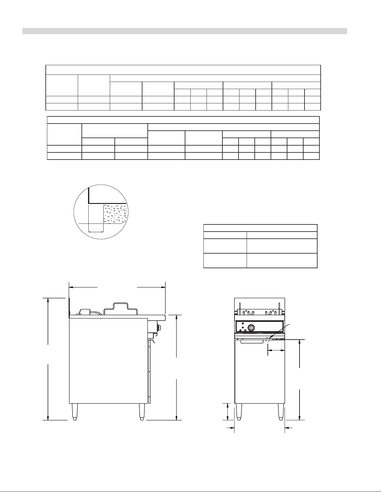
DIMENSIONS AND SPECIFICATIONS
North American (60 cycle) Electrical Loading:
Model
S18F 12 58 50 34 34 34 28.9 28.9 28.9 15 15 15
S18SF 16 77 66.7 49 38 49 41.8 41.8 32.5 21 17 21
Model
S18F 10.1 12 46.2 50 15.4 15.4 15.4 16.7 16.7 16.7
S18SF 13.4 16 61.1 66.7 17.2 26.7 17.2 18.8 29.2 18.8
Total
kW
220/380V 240/415V X Y Z X Y Z
208v/1Ø 240V/1Ø
Export (50 cycle) Electrical Loading:
Total kW
220/380V/ 1Ø240/415V/ 1Ø220/380/3Ø 240/415V/3Ø
Nominal Amperes Per Line
208V/3Ø 240V/3Ø 480V/3Ø
X Y Z X Y Z X Y Z
Nominal Amperes Per Line
DAIS Installation:
FRYER
MAX
2-/12"
[64mm]
Frying area is 13” (330mm) wide x 15-1/2” (394mm) deep.
34-1/2"
[877mm]
43-3/4"
[1111mm]
37-3/4"
[959mm]
Installation Clearances:
Clearance to combustible surfaces
Sides: 1” (25mm) Rear: 1-1/2” (38mm)
NOTE: Many local codes exist, and it is the
responsibility of the Owner and the Installer to comply
with those codes.
Production Capacity (per hour)
Model French Fries
S18F
S18SF
Frozen to Done
50 lbs. /23kg
Frozen to Done
60 lbs./ 27kg
REAR
ELECTRICAL
CONNECTION
6"
[152mm]
28-7/8"
[733mm]
6"
[152mm]
18"
[457mm]
Frying area is 13" (330mm) wide x 15-1/2" (394mm) deep
Part # P156 Rev 1 (12/03/09)Page 4
Page 5
DIMENSIONS AND SPECIFICATIONS continued
Exterior Dimensions
Model Height* Width Depth Weight
S18-(F,SF) 37-3/4” (959mm) 18” (457mm) 34-1/2” (876mm) 140Lb/64Kg
* Height from front rail to oor
NOTE: Height Dimensions specied with 6” (152mm) legs.
INTRODUCTION
The following instructions should be read carefully as the
manufacturer can not be held responsible for any damage
to property or persons caused by incorrect installation or
operation of the equipment.
General Information
1. Check the crate for possible damage sustained during
transit. Carefully remove the unit from the crate and
again check for damage. Any damage to the unit must be
reported to the carrier immediately.
2. Any protective material covering stainless steel parts
must be removed.
3. All fryers are shipped from the factory with legs or casters
tted unless specially ordered without.
4. The type of voltage supply that the equipment was
manufactured for at the factory is noted on the data plate
and on the packaging. This type of supply must be used.
5. Do not remove permanently axed labels, warnings
or data plates from the appliance, for this may void
approvals and creates a safety hazard.
Safety
This manual pertains to fryers. The reader/operator must
interpret its contents to applicable needs. If there is any
question of interpretation of any of the literature pertaining
to Garland fryers, please contact your Authorized Service
Agency or our Customer Service Department at the phone
number listed on the front of this manual.
A qualied person must make the installation of these
products in accordance with the local codes of the country of
destination.
Always follow these safety precautions when operating the
fryer.
The unit must only be operated by qualied persons. DO
NOT operate without reading this manual.
DO NOT operate the product unless it has been properly
installed and earthed.
DO NOT operate the product unless all service and access
panels are in place and fastened properly.
DO NOT attempt to repair or replace any part of this product
unless all main power supplies have been disconnected.
WARNING: to avoid serious personal injury:
Use extreme caution in setting up, operating and cleaning
this product to avoid coming in contact with hot surfaces
or hot oil. Suitable protective clothing should be worn to
prevent the risk of burns.
NOTE all warning labels and markings on the product,
which call attention to further dangers and necessary
precautions.
WARNING: this appliance must not be cleaned with a water
jet.
Part # P156 Rev 1 (12/03/09) Page 5
Page 6

INTRODUCTION continued
Rating Plate
For proper operation, the information on the data plate of
the new equipment must match the electrical supply. The
data plate is readily accessible, located on the inside of the
cabinet door. It contains all of the pertinent information
required by the installer.
INSTALLATION
The Garland S18 series deep fat fryer complies with the
standards CSA C22.2 No. 109 – latest edition, the UL197 –
latest edition and the NSF#4 – latest edition. The installation
& connection of this appliance must comply with current
codes. In Canada – the Canadian Electric Code Part 1 and in
the USA – The National Electrical Code.
This equipment must be installed and adjusted by a
competent person as required by the local electrical
authorities. Failure to install appliances correctly could lead
to prosecution. It is in your own interests and that of safety to
ensure that the law is complied with.
Unpacking
1. Carefully remove the unit from the crate. All packing
material must be removed from the unit. The protective
material covering the stainless steel must be removed
immediately after the unit is installed.
2. Do not remove permanently axed labels, warnings
or data plates from the appliance, for this may void
approvals and creates a safety hazard.
Clearances
The space in which the appliance is to be sited must include
the minimum installation clearances to combustible surfaces
as indicated in the following table.
When corresponding with the factory or equipment dealer
regarding service problems or replacement parts, be sure
to refer to the particular unit by the correct model number,
including prex and sux letters and numbers and serial
number. The rating plate axed to the unit contains this
information.
CLEARANCE TO COMBUSTIBLE MATERIAL
Location All Models
Top *
Left Hand Side 1” (25mm)
Right Hand Side 1” (25mm)
Rear 1.5” (38mm)
Type of Floor or Base Combustible
* NOTE Equipment must be installed under a
ventilation canopy
Adequate clearance must be provided for servicing,
ventilation & proper operation. The product must be kept
free from combustible material.
Siting
The fryer should be installed on a rm smooth and level oor
designed to withstand the weight of the appliance and any
ancillary equipment. (Refer to dimensions and specications
section for weights). Once in position check that the
equipment is level, the fryer must be level front to back, side
to side and diagonally. This leveling must be done with the
unit under the hood and in it’s normal operational position.
Adjust if necessary.
If the fryer is to be dais or cove mounted, the base on which
it is to be set should be level. If it is not, the fryer must be
shimmed to level.
Part # P156 Rev 1 (12/03/09)Page 6
Page 7

INSTALLATION continued
Appliances Equipped With Legs
All Fryers are shipped from the factory with legs installed
unless otherwise specied. When the fryer is specied for
dais or cove mounting it is shipped less legs. Legs must be
adjusted to a minimum height of 6” (152mm) in order to
comply with NSF standards.
Appliances Equipped With Casters
1. The front casters on the unit are equipped with brakes to
limit the movement of the fryer without depending on
the electrical connection.
2. A restraint can be attached to the unit near the electrical
connection. If the restraint is disconnected be sure to
reconnect it after the fryer has been returned to its
original installed position.
Ventilation
The area in which the appliance is installed must be
adequately ventilated to provide air for removal of steam,
heat generated by the appliance, etc. These products are
intended to be installed under a ventilation hood. The use
of a mechanical extract system should be considered and
conform to local codes.
Proper operation of exhaust fans (proper speed, rotation and
adjustment) is essential. In addition a make-up air system
(HVAC) for the kitchen to supply fresh air is recommended.
Any ventilation system will break down if improperly
maintained. The duct system, the hood, and the lters must
be cleaned on a regular bases and kept clean.
The supply entrance is located at the rear. The supply
terminal block is accessible from the front. The electrical
supply must be adequate for the voltage, phase & current
marked on the rating plate.
NOTE: A means of disconnection from the supply having
a contact separation of at least 3 mm in all poles must be
incorporated in the xed wiring.
This equipment is intended to be installed with xed
permanent wiring.
WARNING: This appliance must be earthed.
Single and Three Phase Connection
Unless otherwise noted all fryers are shipped from the
factory for three phase connection. A wiring diagram is
attached to the rear of each fryer. Visually check all the
electrical connections. The fryer is wired at the factory
as specied on the order. If it is necessary to change the
phasing, refer to the wiring diagram.
NOTE: SF 3 phase loads are unbalanced, see Appendix, rating
plate or consult factory for more details.
Commissioning
Ensure all circuit breakers located in the lower compartment
are set to the ‘ON’ (1) position.
1. Ensure that all controls are in the o position and turn on
the main electrical supply.
2. Operate the fryer in accordance with the operating
instructions in the operating manual.
Electrical Supply
CAUTION: Prior to installation check the electrical supply
to ensure input voltage and phase match the equipment
voltage rating and phase. See data plate located inside of the
cabinet door.
Part # P156 Rev 1 (12/03/09) Page 7
3. Check that the product functions correctly and that the
voltage supply to the unit does not drop by more than
5% when all sections are operated simultaneously.
When the operation has been check, hand the operating
manual to the user or purchaser for retention and instruct
them in the ecient and safe operation of the appliance.
Page 8

MAINTENANCE AND CLEANING
Regular servicing by a competent person is recommended to
ensure the continued safe and ecient performance of the
appliance.
Thermostat Calibration
WARNING: Turn o the electrical mains before commencing
any service work.
It is normal for an electromechanical thermostat to cycle
with a 45° F - 50°F (25°C - 28°C). When checking calibration,
allow the thermostat to cycle a minimum of two times.
1. Place the thermocouple of the test instrument in the
center of the tank 1” (25mm) below the oil surface.
2. Turn the thermostat dial to 325° F (163° C). In order to
allow the oil temperature to stabilize, the control must be
allowed to cycle twice before taking a test reading.
REPLACEMENT OF PARTS
3. Check the temperature reading just when the control
cycles “OFF” as indicated by the cycle pilot lamp. If the
temperature does not read within 15°F (8°C) of the dial
setting, recalibrate as follows:
4. Carefully remove the thermostat dial, not disturbing the
dial setting.
5. Hold the thermostat shaft steady and with a small at
blade screw driver, turn the calibration screw located
inside the shaft clockwise to decrease the temperature
and counter clock wise to increase the temperature.
NOTE: Each 1/4 turn of the screwdriver will create a
change of approximately 35° F (20° C).
6. Replace the thermostat dial and repeat steps 1 through 3
to verify that correct adjustment has been made.
WARNING: Turn o the electrical mains before commencing
any servicing work.
Thermostat
1. Remove the screws securing the front panel to the front
rail and drop the panel.
2. Disconnect the wires from the taps on the thermostat.
3. Remove the dial from the thermostat and the screws
securing the thermostat body to the control panel
4. Remove the wires from the thermostat terminals. Be sure
to note which wire connects to which terminal on the
thermostat.
5. Remove the thermostat sense bulb. Note the path of the
capillary and install the new one in the same manner.
6. Replace the faulty thermostat and reassemble in the
reverse order.
Indicator Lamps
1. Remove the screws securing the front panel to the front
rail and drop the panel.
2. Disconnect the supply wires to the lamp body and
remove the faulty lamp.
3. Reassemble in the reverse order.
Heating Elements
1. Tilt rotating element head up and remove the element
terminal cover.
2. Disconnect the supply wires to the element.
3. Remove the sealing connectors.
4. Reassemble in the reverse order replacing the sealing
connectors.
Part # P156 Rev 1 (12/03/09)Page 8
Page 9

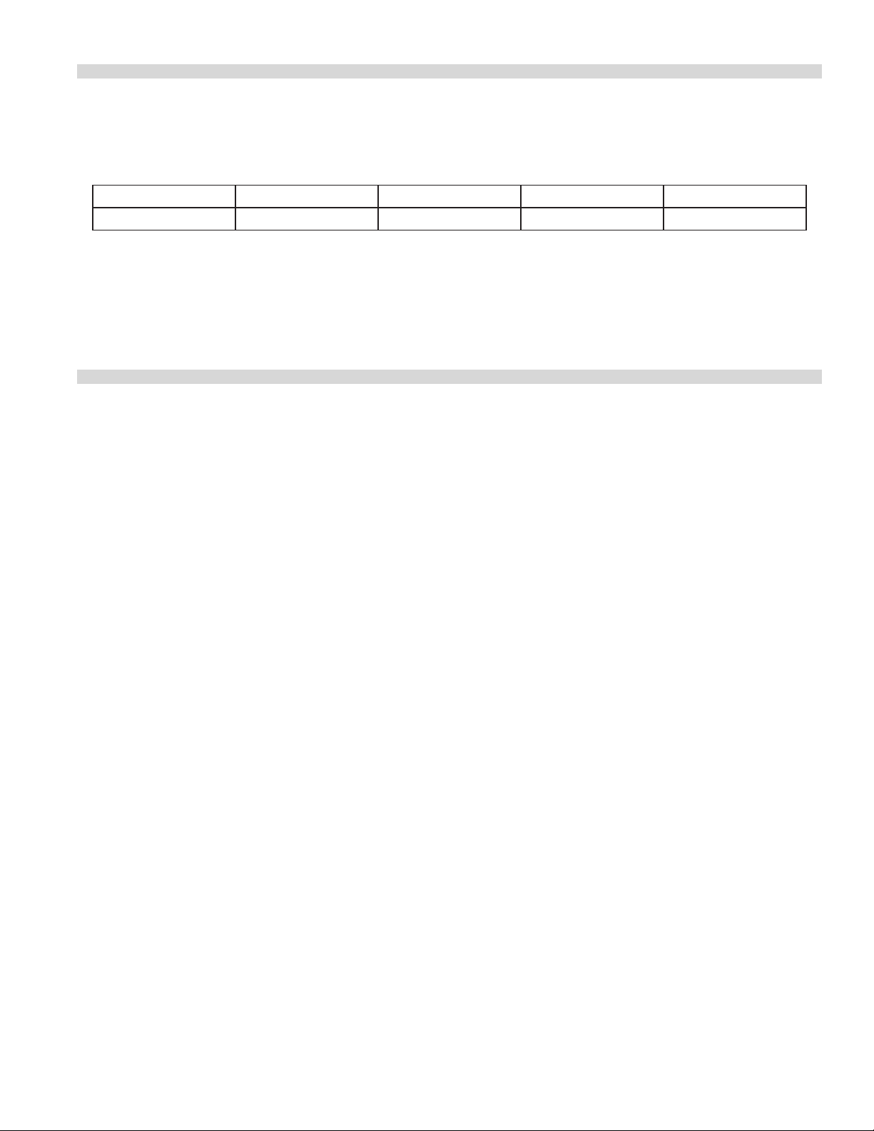
FAULT FINDING
FRYER DIAGNOSTICS
PROBLEM POSSIBLE CAUSE SOLUTION
Power indicator is on.
Heating indicator comes on.
Fryer recovering or heating unevenly.
Red indicator light is on.
Fryer is not heating.
Fryer will not start - green indicator
does not come on.
Red indicator light is not on.
Oil temperature too hot or too cold. Thermostat is out of calibration. Calibrate or replace thermostat.
One or more circuit breakers are o. Switch circuit breakers to the “ON”
position.
One or more elements are defective. Replace Elements.
High temperature limit is tripped Operating thermostat may be defective
- Replace.
Operating contractor may be defective
- Replace
Power switch is defective Replace Power Switch
Safety Contactor is defective Replace Contactor.
Auxiliary contacts on the thermostat
are defective.
Replace operating thermostat.
Part # P156 Rev 1 (12/03/09) Page 9
Page 10

APPENDIX
Wiring diagrams
Part # P156 Rev 1 (12/03/09)Page 10
Page 11

TH1
GREEN
RED
AMBER
4kW/4.5kW
4kW/7.0kW
4kW/4.5kW
K
S1-2
K2
Z
1 PHASE
4
X
Y
3
5
G
1
Z
3 PHASE
4
2
X
Y
6
5
3
G
1
TH2
S1-1
2
6
MISSISSAUGA, ONTARIO, CANADA
4
GARLAND COMMERCIAL RANGES LIMITED
454443424140
30A
S18F, SF (208/240 VAC)
X
Z
Y
SCHEMATIC DIAGRAM
F=30A
SF=40A
6 35 2
20
22
30A
1
23
TH2
HIGH LIMIT
COM NO NC
30
19
13
1817
41
12
45
K
CONTACTOR
REGULATING
15
19
43
11
26
20
17
21
TH1
THERMOSTAT
200°-375° F
:
MODEL
28
21
12
16
15
13
10
24
AMBER, HEATING
16
42
44
F=4.0kW F=4.0kW F=4.0kW
SF=4.5kW SF=7.0kW SF=4.5kW
22
14
40
K2
29
27
11
LIMIT CONTACTOR
18
14
24
10
GREEN, POWER ON
25
28
30
2926
S
SWITCH
CIRCUIT 1
TOP
RED, t>LIMIT
CIRCUIT 2
25
23
3013800
:
DWG
Part # P156 Rev 1 (12/03/09) Page 11
Page 12

N
L3
TH1
GREEN
AMBER
4kW/4.5kW
4kW/4.5kW
RED
4kW/7.0kW
K
K2
S1-2
1 PHASE
7
L2
3
E
L1
N
L3
2
3 PHASE
1
L2
2
3
E
L1
1
6
4
TH2
S1-1
N
L3
L1
L2
SCHEMATIC DIAGRAM
5
4
4241
29
26
40
27
TH2
HIGH LIMIT
COM NO NC
28
6
5
7
3
MISSISSAUGA, ONTARIO, CANADA
GARLAND COMMERCIAL RANGES LIMITED
S18F, SF (220/380, 240/415 VAC)
:
30A
30A
F=30A
SF=40A
2
1
MODEL
710
4
30
10
11
K
CONTACTOR
REGULATING
16
15
14
17
6
18
18
22
25
TH1
THERMOSTAT
19
200°-375° F
17
13
11
24
512
40
15
16
41
F=4.0kW F=4.0kW F=4.0kW
SF=4.5kW SF=7.0kW SF=4.5kW
42
26
23
22
K2
LIMIT CONTACTOR
14
19
20
AMBER, HEATING
GREEN, POWER ON
28
2325
S
SWITCH
CIRCUIT 1
TOP
RED, t>LIMIT
CIRCUIT 2
20
27
3013801
:
21
DWG
Part # P156 Rev 1 (12/03/09)Page 12
Page 13

TH1
GREEN
RED
K2
4kW/4.5kW
4kW/7.0kW
4kW/4.5kW
AMBER
K
S1-2
Z
1 PHASE
4
2
TH2
X
Y
3
5
G
1
6
Z
3 PHASE
2
4
X
Y
1
5
3
G
6
S1-1
MISSISSAUGA, ONTARIO, CANADA
GARLAND COMMERCIAL RANGES LIMITED
27
32
H4
H2
33
X
Z
Y
SCHEMATIC DIAGRAM
H3
H
31
X
33
X2 X3
X4
S18F, SF (380, 480 VAC)
:
29
20
MODEL
22
23
TH2
HIGH LIMIT
COM NO NC
30
19
13
1817
5
31
20
4
2
K
CONTACTOR
REGULATING
15
19
11
26
17
21
TH1
THERMOSTAT
200°-375° F
28
21
16
15
13
10
AMBER, HEATING
16
6
18
3
F=4.0kW F=4.0kW F=4.0kW
SF=4.5kW SF=7.0kW SF=4.5kW
22
14
1
K2
32
27
11
LIMIT CONTACTOR
14
10
GREEN, POWER ON
25
28
30
2926
S
SWITCH
CIRCUIT 1
TOP
RED, t>LIMIT
CIRCUIT 2
25
23
3013802
:
DWG
Part # P156 Rev 1 (12/03/09) Page 13
Page 14

TH1
GREEN
RED
K2
4kW/4.5kW
4kW/7.0kW
4kW/4.5kW
AMBER
K
S1-2
Z
1 PHASE
4
2
TH2
X
Y
3
5
G
1
6
Z
3 PHASE
2
4
X
Y
1
5
3
G
6
S1-1
MISSISSAUGA, ONTARIO, CANADA
GARLAND COMMERCIAL RANGES LIMITED
27
32
H2
33
X
Z
Y
SCHEMATIC DIAGRAM
H3
H
31
X
H4
33
X2 X3
X4
S18F, SF (380, 480 VAC)
:
29
20
MODEL
22
23
TH2
HIGH LIMIT
COM NO NC
30
19
13
1817
5
31
20
4
2
K
CONTACTOR
REGULATING
15
19
11
26
17
21
TH1
THERMOSTAT
200°-375° F
28
21
16
15
13
10
AMBER, HEATING
16
6
18
3
F=4.0kW F=4.0kW F=4.0kW
SF=4.5kW SF=7.0kW SF=4.5kW
22
14
1
K2
32
27
11
LIMIT CONTACTOR
14
10
GREEN, POWER ON
25
28
30
2926
S
SWITCH
CIRCUIT 1
TOP
RED, t>LIMIT
CIRCUIT 2
25
23
3013802
:
DWG
Part # P156 Rev 1 (12/03/09)Page 14
Page 15

Part # P156 Rev 1 (12/03/09) Page 15
Page 16

 Loading...