

Page 1
INSTALLATION AND
OPERATION MANUAL
MASTER SERIES
INFRA-RED
SALAMANDER BROILER
M/MS/MST (SRC, SR16)
FOR YOUR SAFETY:
DO NOT STORE OR USE GASOLINE
OR OTHER FLAMMABLE VAPORS OR
LIQUIDS IN THE VICINITY OF
THIS OR ANY OTHER
APPLIANCE
WARNING:
IMPROPER INSTALLATION, ADJUSTMENT,
ALTERATION, SERVICE OR MAINTENANCE
CAN CAUSE PROPERTY DAMAGE, INJURY,
OR DEATH. READ THE INSTALLATION,
OPERATING AND MAINTENANCE
INSTRUCTIONS THOROUGHLY
BEFORE INSTALLING OR
SERVICING THIS EQUIPMENT
PLEASE READ ALL SECTIONS OF THIS MANUAL
AND RETAIN FOR FUTURE REFERENCE.
THIS PRODUCT HAS BEEN CERTIFIED AS
COMMERCIAL COOKING EQUIPMENT AND
MUST BE INSTALLED BY PROFESSIONAL
PERSONNEL AS SPECIFIED.
IN THE COMMONWEALTH OF MASSACHUSETTS
THIS PRODUCT MUST BE INSTALLED BY A
LICENSED PLUMBER OR GAS FITTER. APPROVAL
NUMBER: G-1-07-05-28
For Your Safety:
Post in a prominent location, instructions to be
followed in the event the user smells gas. This
information shall be obtained by consulting
your local gas supplier.
Users are cautioned that maintenance and repairs must be performed by a Garland authorized service agent
using genuine Garland replacement parts. Garland will have no obligation with respect to any product that has been
improperly installed, adjusted, operated or not maintained in accordance with national and local codes or installation
instructions provided with the product, or any product that has its serial number defaced, obliterated or removed,
or which has been modified or repaired using unauthorized parts or by unauthorized service agents.
For a list of authorized service agents, please refer to the Garland web site at http://www.garland-group.com.
The information contained herein, (including design and parts specifications), may be superseded and is subject
to change without notice.
GARLAND COMMERCIAL INDUSTRIES
185 East South Street
Freeland, Pennsylvania 18224
Phone: (570) 636-1000
Fax: (570) 636-3903
Part # 1382684 (01/08) © 2005 Garland Commercial Industries, Inc.
Part # 1382684 (01/08) Page 1
GARLAND COMMERCIAL RANGES, LTD.
1177 Kamato Road, Mississauga, Ontario L4W 1X4
CANADA
Phone: 905-624-0260
Fax: 905-624-5669
Enodis UK LTD.
Swallow eld Way, Hayes, Middlesex UB3 1DQ ENGLAND
Telephone: 081-561-0433
Fax: 081-848-0041
Page 2

IMPORTANT INFORMATION
WARNING:
This product contains chemicals known to the state of California to cause cancer and/or birth defects
or other reproductive harm. Installation and servicing of this product could expose you to airborne
particles of glass wool/ceramic fibers. Inhalation of airborne particles of glass wool/ceramic fibers
is known to the state of California to cause cancer. Operation of this product could expose you to
carbon monoxide if not adjusted properly. Inhalation of carbon monoxide is known to the state of
California to cause birth defects or other reproductive harm.
Keep appliance area free and clear of combustibles.
Part # 1382684 (01/08)Page 2
Page 3

TABLE OF CONTENTS
IMPORTANT INFORMATION. . . . . . . . . . . . . 2
DIMENSIONS AND SPECIFICATIONS . . . . . 4
Sux Denitions . . . . . . . . . . . . . . . . . . . . . . . . . . . . . 5
INTRODUCTION. . . . . . . . . . . . . . . . . . . . . . . . 5
Product application . . . . . . . . . . . . . . . . . . . . . . . . . .5
Rating Plate . . . . . . . . . . . . . . . . . . . . . . . . . . . . . . . . . . 5
INSTALLATION . . . . . . . . . . . . . . . . . . . . . . . . . 6
Clearances . . . . . . . . . . . . . . . . . . . . . . . . . . . . . . . . . . . 6
Location . . . . . . . . . . . . . . . . . . . . . . . . . . . . . . . . . . . . . 6
Installation Instructions for
Range Mount Salamander . . . . . . . . . . . . . . . . . . . . 6
Wall Mounted Salamanders . . . . . . . . . . . . . . . . . .6
Statutory Regulations . . . . . . . . . . . . . . . . . . . . . . . . 6
Gas Supply . . . . . . . . . . . . . . . . . . . . . . . . . . . . . . . . . . 7
OPERATION. . . . . . . . . . . . . . . . . . . . . . . . . . . . 8
M, MS Models . . . . . . . . . . . . . . . . . . . . . . . . . . . . . . .8
Pilot Lighting Instructions . . . . . . . . . . . . . . . . 8
Main Burner Operation . . . . . . . . . . . . . . . . . . . 8
Shut Down. . . . . . . . . . . . . . . . . . . . . . . . . . . . . . . 8
MST Models . . . . . . . . . . . . . . . . . . . . . . . . . . . . . . . . . 8
Operating Controls . . . . . . . . . . . . . . . . . . . . . . . 8
Lighting Instructions . . . . . . . . . . . . . . . . . . . . . 8
Shut Down. . . . . . . . . . . . . . . . . . . . . . . . . . . . . . . 9
All Models . . . . . . . . . . . . . . . . . . . . . . . . . . . . . . . . . . . 9
Burner Ignition. . . . . . . . . . . . . . . . . . . . . . . . . . . 9
Main burner Adjustments. . . . . . . . . . . . . . . . . 9
Burn o Period . . . . . . . . . . . . . . . . . . . . . . . . . . . 9
Operating Suggestions . . . . . . . . . . . . . . . . . . . 9
Energy Conservation . . . . . . . . . . . . . . . . . . . . . 9
Safety Precautions. . . . . . . . . . . . . . . . . . . . . . . . 9
Ventilation and Air Supply . . . . . . . . . . . . . . . . . . . . 7
Testing And Adjustments . . . . . . . . . . . . . . . . . . . . . 7
MAINTENANCE AND CLEANING . . . . . . . . 10
Daily . . . . . . . . . . . . . . . . . . . . . . . . . . . . . . . . . . . . . . . 10
Monthly . . . . . . . . . . . . . . . . . . . . . . . . . . . . . . . . . . . .10
Exterior Cleaning . . . . . . . . . . . . . . . . . . . . . . . . . . . 10
Stainless Steel . . . . . . . . . . . . . . . . . . . . . . . . . . . . . .10
SERVICING. . . . . . . . . . . . . . . . . . . . . . . . . . . . 11
SAFETY. . . . . . . . . . . . . . . . . . . . . . . . . . . . . . . 11
Part # 1382684 (01/08) Page 3
Page 4
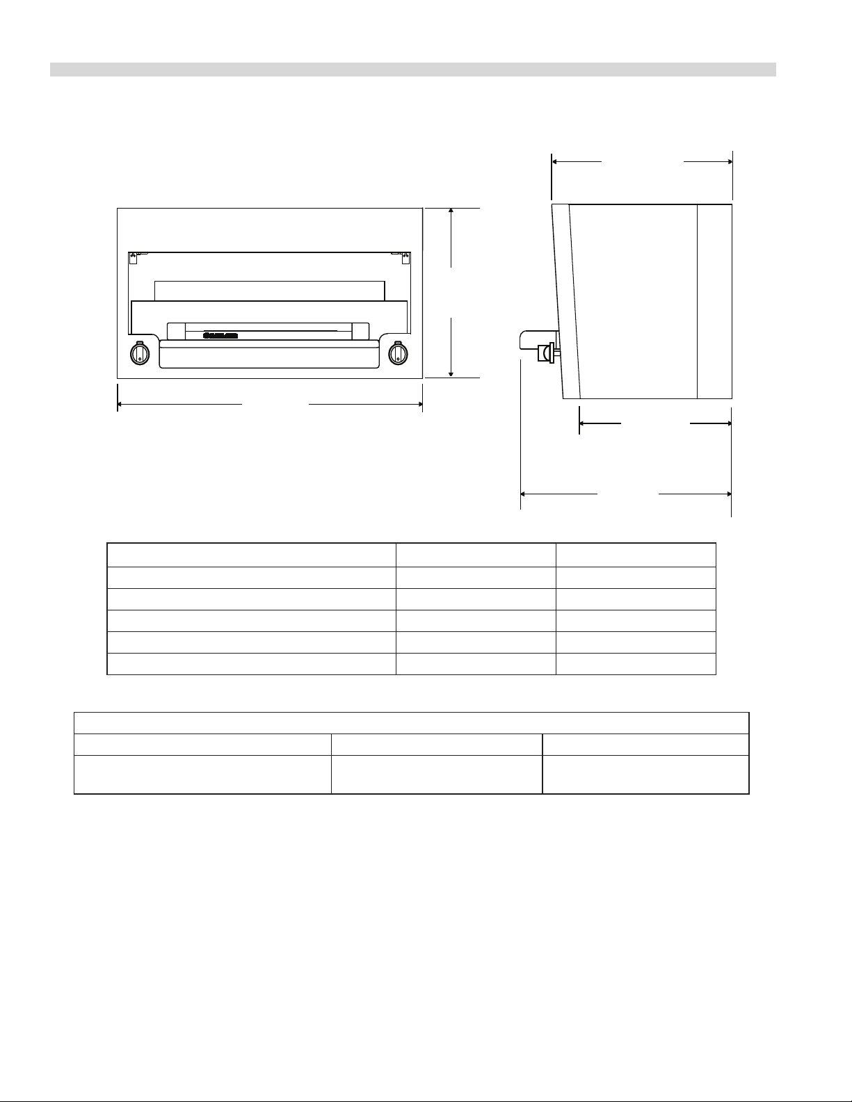
DIMENSIONS AND SPECIFICATIONS
16 5/16"
[414mm]
34"
[864mm]
17 61/64"
[456mm]
16 13/16"
[427mm]
20 1/4"
[514mm]
PRODUCT MSR16 MRSC
Width: In(mm) 34(864) 34(864)
Depth: In(mm) 20-1/4(514) 20-1/4(514
Height: In(mm) 35-5/8(965) 17(432)
INPUT:BTU/hr(kw)(Natural Gas) 28,000 (8.20) 28,000 (8.20)
Shipping Wt:(LB/KG) 170/78 135/61
INSTALLATION NOTES
Combustible Wall Clearances ¹ Entry Clearances Operating Pressure
Sides: 0"
Back: 0"
¹ For instillations in non-combustible locations only.
NOTE: Data applies only to North America
Gas input ratings shown here are for installations up to 2,000 ft. (610m) above seal level. Specify altitudes over 2,000 ft.
Commercial cooking equipment requires an adequate ventilation system. For additional information, refer to the
National Fire Protection Association's standard NFPA96. “Vapor Removal from Cooking equipment”
(for North American only)
Please specify gas type when ordering.
Crated: 26-3/4" (680mm)
Uncrated: 21" (533mm)
Natural: 6" WC (15mbar)
Propane: 11" WC (28mbar)
Part # 1382684 (01/08)Page 4
Page 5

DIMENSIONS AND SPECIFICATIONS continued
M/MS/MST SRC, SR16-280, SR16
SRC - Counter Top Version
SR16-280 - Restaurant Range Mount Version
SR16 - Heavy Duty Range Mount Version
Base Model Number
GAS TYPE
MODEL NUMBER
(M,MS,MST)(SRC, SR16) 47F 14,000 1.1mm 13,000
Sux Denitions
Natural Gas Propane
Orice Input (BTU/Hr) Orice Input (BTU/Hr)
INTRODUCTION
IMPORTANT: Read these instructions carefully before
attempting to operate the appliance.
Garland/U.S. Range products are not approved or authorized
for home or residential use, but are intended for commercial
applications only. Garland / U.S. Range will not provide
service, warranty, maintenance or support of any kind other
than in commercial applications.
Your new equipment must be installed and adjusted by a
competent person in accordance with the law. Failure to
install appliances correctly could lead to prosecution. It is
in your own interests and that of safety to ensure that the
law is complied with. Your Garland dealer is well qualied to
provide this service.
Like any other ne precision built piece of equipment, it
should be given regular care and maintenance. Periodic
inspections by your dealer or a qualied service company are
recommended to check temperatures, burner adjustments
and ensure moving parts are operative. Wherever possible
avoid overheating idle equipment, as this is the primary
cause for increased service cost.
“Regular Maintenance Ensures Peak Performance.”
Product application
The Garland infra-red salamander oers broiling for a wide
variety of products such as steak, lobster, sh, onion soup,
casseroles, garlic bread and hamburgers. The oven-re infrared design provides for quick preheat and ecient, uniform
production. The tilting rack feature allows for an easy view
broiling.
Rating Plate
The rating plate is located behind the drip tray. In the event
you have any questions concerning the installation, use
care or service of this or any other Garland product, write or
call our Product Service Department. When corresponding
with the factory or your equipment dealer regarding
service problems or replacement parts, be sure to refer to
the particular unit by the correct model number (including
prex and sux letters and numbers) and the serial or code
number. The rating plate axed to the unit contains this
information.
For proper operation, the Fuel information on the data plate
of you new equipment must match your fuel supply.
Part # 1382684 (01/08) Page 5
Page 6

INSTALLATION
~
1
"X"
"X"
2
8
4
3
6
7
5
GARLAND
Clearances
Models (M, MS, MST)(SRC, SR16) are for installation in noncombustible locations only with zero (0”) sides and rear
clearance.
NOTE: Adequate clearance must be provided for servicing
and proper operation.
Location
Counter salamanders should be installed on a rm, smooth
and level base designed to withstand the weight of the fully
laden appliance. Any openings in the wall behind or beside
the appliance must be sealed.
Installation Instructions for
Range Mount Salamander
4. If the range is in a battery line-up, fasten units together
at the hole marked “X” with 1/4” x 20 bolts, nuts and
washers.
5. Reattach the front panel (5) to the salamander with sheet
metal screws previously removed.
Wall Mounted Salamanders
1. Each gas appliance must be located with respect to
building construction and other equipment so as to
permit access to the appliance, Such access and clearance
may be necessary for servicing and cleaning.
2. Salamanders intended for wall mounting are shipped
with the mounting kit already attached.
3. Provisions for gas connections, bottom or rear should be
taken into consideration.
1. Remove the front panel (5) by removing two (2), sheet
metal screws from the underside of the salamander.
2. With the back panel, (4), still attached to the uprights
(2&3) drop the uprights into the rectangular openings at
the rear of the range (1).
3. Fasten the uprights, (2 & 3) to the range with four, (4),
5/16” x 18 bolts and at washers. (6&7)
Statutory Regulations
When checking gas pressure be sure that all other
equipment on the same gas line is on. A pressure regulator is
supplied as standard equipment with Garland salamanders.
Installation must conform to the National Fuel Gas Code ANSI
Z223.1 or latest edition and/or local code to assure safe and
ecient operation.
In Canada, the installation must comply with
CAN/CGA-B149.1 Natural Gas Installation Code or CAN/CGAB149.2 Propane Gas Installation Code, and local codes where
applicable.
NOTE: The appliance must be isolated from the gas supply
piping system by closing it individual manual shut-o (not
supplied by the manufacturer) during any testing of the gas
supply piping system at test pressures equal to or less than
1/2 PSIG (3.45 kPa).
Part # 1382684 (01/08)Page 6
Page 7

INSTALLATION continued
Gas Supply
Before assembly and connection check the gas supply.
1. The type of gas for which the unit is equipped is stamped
on the data plate located behind the drip tray. Connect
a unit stamped “NAT” only to natural gas; connect those
stamped “PRO” only to propane gas.
2. If it is a new installation have the gas authorities check
the meter size and piping to assure that the unit is
supplied with sucient amount of gas pressure required
to operate the unit.
3. If it is an additional or replacement equipment have the
gas authorities check the pressure to make certain that
the existing meter and piping will supply fuel to the unit
with not more than 1/2” water column pressure drop.
WARNING: Check gas connections for leaks. Use a soap
solution or similar means. DO NOT USE AN OPEN FLAME.
NOTE: This appliance is not recommended for residential
installation.
Ventilation and Air Supply
Proper ventilation is highly important for good operation.
The ideal method of ventilation for a Salamander broiler is
the use of a properly designed canopy hood, which should
extend six (6”, 152 mm) beyond all sides of the appliance and
six (6) feet six (6) inches (1981 mm) from the oor.
A strong exhaust fan will create a vacuum in the room. For an
exhaust system to work properly, replacement air must enter
the room in which the vent is located. The amount of air that
is exhausted must equal the amount entering, (make-up air).
All gas burners and pilots need sucient air to operate and
large objects should not be placed in front or on the top of
the broiler, which would obstruct the airow though, the
front of the broiler.
For your safety NEVER place any type of object on top of
the salamander broiler or cheese meters. The top of the
broiler will exceed 1000°F. It could cause severe burns or
re and obstruct ventilation.
Testing And Adjustments
All ttings and pipe connections must be tested for leaks.
Use approved gas leak detectors, soap solution or equivalent,
checking over and around the ttings and pipe connections.
DO NOT USE A FLAME! Accessibility to all gas lines and
ttings require that valve panel(s), lower front panel(s) be
removed. It may be necessary to remove or at least raise and
secure top grates. All parts removed (including fasteners)
should be stored safely for re-use.
Testing
1. Be sure all valves are in the “OFF” position
2. Turn on the main gas supply valve. Light all top section
pilots.
3. Leak test all valves and ttings as described in the
procedure above. Correct any leaks as required and
recheck.
4. Shut o all gas valves.
All units are tested and adjusted at the factory. However,
burners and pilots should be checked at installation and
adjusted if necessary.
Part # 1382684 (01/08) Page 7
Page 8

OPERATION
OFF
IGNITION
MAX
MIN
NOTE: Ensure the gas supply to the appliance is turned “ON”.
During the initial ignition cycle, air must be purged from the
gas line and thus it may take one to two minutes for the pilot
burner to ignite.
M,MS Models
Pilot Lighting Instructions
1. The in-line service shut-o valve should be in the “ON”
position.
2. With a lighted taper light the pilots which are located at
the rear of the main burner.
3. The pilot ame should be approximately 7/8”
(22 mm) long for proper ignition of the burners. The
pilot adjustment valve is located by sliding the drip
tray forward. The adjustment valves are located on the
manifold pipe, which runs horizontally across the back of
the unit, behind the drip tray, one is at the left rear and
the other is at the right rear.
4. To adjust the pilot light, turn the brass screw counterclockwise to increase the pilot ame, and clockwise to
decrease the ame.
MST Models
Operating Controls
NOTE: No more than 7/8” (22 mm) pilot ame length should
be required. Too high a setting will cause the ame to lift o
or will create excessive carboning. Do not adjust the pilot
ame lower than 7/8” (22mm) long because this can cause
delayed ignition at the burner. The delayed ignition could
cause the burner tiles to crack, in that case the burner would
have to be replaced.
Main Burner Operation
1. Turn the main burner to the “MAX” position.
2. Immediately check ignition of the burner.
CAUTION: Should ignition fail after ve (5) seconds, turn the
valve o and wait ve (5) minutes before trying again. The
pilot gas is not interrupted automatically, it is the responsibility
of the operator to check the ignition of the burners
immediately after the burner valve has been turned on.
Shut Down
1. Turn all valves to the “OFF” position by rotating the knob
clockwise 1/4 turn.
2. If the unit is to be shut down for an extended period of
time close the inline gas valve.
Lighting Instructions
1. Push in the tap and turn it counter-clockwise to the
Ignition Position “ ”
2. Holding the tap fully in, light the pilot with a match or
taper.
Part # 1382684 (01/08)Page 8
Page 9

OPERATION continued
3. When the pilot is lit, continue to hold the tap fully in for
20 seconds, then release it. IF the pilot goes out, wait for
ve (5) minutes, and then repeat from step 1.
4. When the pilot is established, push the tap in again and
turn it counter-clockwise to the full ame position “ ”
thus lighting the main burner.
5. For low ame or simmer, push the tap in and turn it
counter-clockwise to the low ame “ ” position.
6. To shut the burner o, turn the dial to the “ ” symbol and
the safety device will disengage within 60 seconds.
Shut Down
1. Turn all valves to the “OFF” position by rotating the knob
clockwise 1/4 turn.
2. If the unit is to be shut down for an extended period of
time, close the inline gas valve.
All Models
Burner Ignition
When ignition has been accomplished, a blue ame will
cover the surface of the ceramics for 10-15 seconds. This haze
will disappear and the burner rod will glow red. After the
burners have operated for several minutes turn the valve to
“MIN”. The burner rods will no longer glow red and the ame
travels back and forth on the face of the burner ceramics.
Main burner Adjustments
This adjustment has been factory pre-set however, with
changing pressures this adjustment and pilot adjustment
may need re-done after installation. This is not considered a
manufacturing defect and is not warrantable.
Burn o Period
Many parts used in the manufacturing of commercial
equipment have a thin protective coating of machine oil. This
oil should be burned o before the equipment is used for
food preparation.
After all start-up and safety checks have been completed,
turn the burner valve to the “MAX” position. A Smoke (a
bluish haze) will be produced. This process can take several
hours and can be completed over a few days.
Operating Suggestions
1. Clean the racks as soon as possible after cooking with
tomato or vinegar based products that have a high acid
content. These foods can cause pitting of the rack surface.
2. Allow the salamander to preheat before adding product.
3. Drain and clean the drip tray frequently. Excessive oil
drain o in the pan can cause spillover.
Energy Conservation
Do not waste energy by leaving controls at high temperature
settings during idle periods. Lower setting will keep broiler
warm and ready got the next use period. Reset burner valve
knob as required for heavy load periods.
All Salamander are provided with a xed burner orice to
provide 20,000 BTU/Hr at the “MAX” setting on natural gas
supplied at 6.0” W/C pressure and 20,000 BTU/Hr at the “MAX”
setting on propane gas supplied at 10.0” W/C.
The “MIN” setting is adjustable and should be set as follows:
1. Set the burner valve knob to “MIN”.
2. Insert a thin bladed screwdriver into the valve stem
to engage the slot inside the stem. Turn Clockwise to
decrease the rate and counter clock-wise to increase.
Proper adjustment is attained at the point where the burner
rods no longer glow and the ame travels back and forth on
the face of the ceramics.
Part # 1382684 (01/08) Page 9
Safety Precautions
It is the responsibility of the supervisor or equivalent
person to ensure that users of this equipment wear suitable
protective clothing and to draw attention to the fact that
some parts will by necessity become very hot and will cause
burns if touched accidentally.
For your safety never place any type of object on top of the
salamander broiler. The top of the broiler will exceed 1000°F.
It could cause severe burns and/or le and also obstruct
ventilation.
Page 10

MAINTENANCE AND CLEANING
A program of proper cleaning techniques will aid in
continued trouble free operation of this or any quality
equipment.
Daily
1. Remove and clean grid rack. Grid racks should be wiped
clean while still warm, using a heavy cloth or other grease
absorbing material to remove grease and burnt food
before they burn into the grid. Remove burnt materials,
such as carbonized grease or food, with a sti wire brush.
DO NOT USE ANY TYPE OF STEEL WOOL. Small particles
of steel may be left on the grid surface and get into food
products. Grid racks should be washed thoroughly using
a wire brush and a hot, mild detergent or soap solution.
Rinse with clear, warm water.
2. With the rack removed clean the interior of the unit with
a damp cloth.
3. Clean out the grease container.
Monthly
Lubricate valves and bearings as required. Due to the usual
location of the broiler which is mounted above a range
with open tops, the heat from the open top will cause the
lubrication grease inside the valves to dry out. When you
notice that the valves are becoming harder to turn, it is
then time to have them greased. We suggest an authorized
service agent who is familiar with the appliance and working
with natural and propane gas, perform this type of work.
Exterior Cleaning
Establish a regular schedule. Any spills should be wiped o
immediately.
Wipe exposed, cleanable surface when cool with a mild
detergent and hot water. Stubborn residue spots may be
removed with a lightweight non-metallic scouring pad. Dry
thoroughly with a clean cloth.
Stainless Steel
Stainless steel should be cleaned using a mild detergent,
a soft cloth and hot water. If it is necessary to use a nonmetallic scouring pad, always rub in the direction of the
grain in the metal to prevent scratching. Use a water based
stainless steel cleaner (such as Drackett Twinkle), if you
want a high shine. Wash a small area at a time and rinse the
washed area with a clean sponge dipped into a disinfectant
and wipe dry with a soft cloth before it can dry.
Use only stainless steel, wood or plastic tools to scrape
o heavy deposits of grease or oil. Do not use ordinary
steel scrapers or knives, as particles of iron may become
embedded and rust. NEVER USE STEEL WOOL.
Part # 1382684 (01/08)Page 10
Page 11

SERVICING
To ensure ecient and safe operation of the appliance it
is recommended that servicing be carried out at regular
interval, the frequency of which will vary, depending on the
SAFETY
It is essential that the instructions in this booklet are strictly
followed for the safe and economical operation of the
equipment. If it is known or suspected that a fault exists on
the appliance then it must not be used until the fault has
been rectied by a competent person.
installation. Servicing must be carried out by competent
persons in accordance with the law.
Part # 1382684 (01/08) Page 11
Page 12

 Loading...