

Garland MIR34L, IR36-280L, IR-280WL, IR36-380CL, IR60-280L Installation & Operating Manual
...Page 1
INSTALLATION, OPERATING
& SERVICE INSTRUCTIONS
FOR GARLAND INFRA-RED SALAMANDER
BROILERS AND INFRA-RED CHEESE MELTERS
WARNING:
FOR YOUR SAFETY
DO NOT STORE OR USE GASOLINE OR OTHER
FLAMMABLE VAPORS OR LIQUIDS IN THE
VICINITY OF THIS OR ANY OTHER APPLIANCE.
PLEASE READ ALL SECTIONS OF THIS MANUAL AND RETAIN FOR FUTURE REFERENCE.
THIS PRODUCT HAS BEEN CERTIFIED AS COMMERCIAL COOKING EQUIPMENT AND MUST BE INSTALLED
BY PROFESSIONAL PERSONNEL AS SPECIFIED.
IN THE COMMONWEALTH OF MASSACHUSETTS THIS PRODUCT MUST BE INSTALLED BY A LICENSED
PLUMBER OR GAS FITTER. APPROVAL NUMBER: G-1-07-05-28
IMPROPER INSTALLATION, ADJUSTMENT,
ALTERATION, SERVICE OR MAINTENANCE CAN
CAUSE PROPERTY DAMAGE, INJURY OR DEATH.
READ THE INSTALLATION, OPERATION AND
MAINTENANCE INSTRUCTIONS THOROUGHLY
BEFORE INSTALLING OR SERVICING
THIS EQUIPMENT.
For Your Safety:
Post in a prominent location, instructions to be followed in the event the user smells gas. is information shall be
obtained by consulting your local gas supplier.
Users are cautioned that maintenance and repairs must be performed by a Garland authorized service agent using genuine
Garland replacement parts. Garland will have no obligation with respect to any product that has been improperly installed,
adjusted, operated or not maintained in accordance with national and local codes or installation instructions provided
with the product, or any product that has its serial number defaced, obliterated or removed, or which has been modified
or repaired using unauthorized parts or by unauthorized service agents. For a list of authorized service agents, please refer
to the Garland web site at http://www.garland-group.com. e information contained herein, (including design and parts
specifications), may be superseded and is subject to change without notice.
Continuous product improvement is a Garland policy, therefore design and specifications are subject to change without notice.
GARLAND COMMERCIAL INDUSTRIES
185 East South Street
Freeland, Pennsylvania 18224
Phone: (570) 636-1000
Fax: (570) 636-3903
Part # 1382669 (07/05) Page 1
Part # 1382669 (07/05) © 2005 Garland Commercial Industries, Inc.
GARLAND COMMERCIAL RANGES,
LTD.
1177 Kamato Road, Mississauga, Ontario L4W 1X4
CANADA
Phone: 905-624-0260
Fax: 905-624-5669
Enodis UK LTD.
Swallowfield Way, Hayes, Middlesex UB3 1DQ ENGLAND
Telephone: 081-561-0433
Fax: 081-848-0041
Page 2

INTRODUCTION
WARNING:
is product contains chemicals known to the State of California to cause birth defects or other reproductive
harm. Operation of this product could expose you to carbon monoxide if not adjusted properly. Inhalation of
carbon monoxide is known to the State of California to cause birth defects or other reproductive harm.
Keep appliance area free and clear from combustibles
Units included in this manual are:
Salamander Models: MIR34L, IR36-280L,IR-280WL,
IR36-380CL, IR60-280L
Cheese Melter Models: GCM-2C, GCM-3C, GCM-6C,
GCM24-280G, CM36-280,
GCM72-280, MCM34
Part # 1382669 (07/05)Page 2
Page 3

TABLE OF CONTENTS
Introduction . . . . . . . . . . . . . . . . . . . . . . . . 2
Dimensions And Specifications,
Model MIR 34L . . . . . . . . . . . . . . . . . . . . . 4
Dimensions And Specifications,
Model IR-280L Series . . . . . . . . . . . . . . . . . 5
Dimensions And Specifications,
Cheese Melter . . . . . . . . . . . . . . . . . . . . . . . 6
General Information . . . . . . . . . . . . . . . . . . 7
Salamander Performance and Construction . . . . 7
Cheese Melter Performance and Construction . . 7
Rating Plate . . . . . . . . . . . . . . . . . . . . . . . . . . . . 7
Installation . . . . . . . . . . . . . . . . . . . . . . . . . 8
National Code Requirements . . . . . . . . . . . . . . . 8
Operation . . . . . . . . . . . . . . . . . . . . . . . . . 12
Pilot Lighting Instructions . . . . . . . . . . . . . . . . 12
Main Burner Operation . . . . . . . . . . . . . . . . . . 12
Burn off Period . . . . . . . . . . . . . . . . . . . . . . . . . 12
Energy Conservation . . . . . . . . . . . . . . . . . . . . 12
Shut Down Instructions . . . . . . . . . . . . . . . . . . 12
Main Burner Adjustments . . . . . . . . . . . . . . . . 12
Maintenance And Cleaning . . . . . . . . . . . 13
Daily . . . . . . . . . . . . . . . . . . . . . . . . . . . . . . . . 13
Monthly . . . . . . . . . . . . . . . . . . . . . . . . . . . . . . 13
Exterior Cleaning . . . . . . . . . . . . . . . . . . . . . . . 13
Gas Connections . . . . . . . . . . . . . . . . . . . . . . . . 8
Pressure Regulators in Battery Installations. . . . . 8
Installation of Salamander to a Range. . . . . . . . . 9
Assembly Instructions Salamander/Cheese Melters
M-Series Salamanders/Cheese Melters . . . . . . . 9
Models IR60-280L, GCM60-280 . . . . . . . . . . 10
Models IR48-280L IR72-280L, GCM48-280,
GCM72-280 . . . . . . . . . . . . . . . . . . . . . . . . . . . 10
Models IR48-280L or GCM48-280 Mounting to
48” Range with one Full Size Oven . . . . . . . . . 10
Wall Mounted Salamanders, Cheese Melters or
Counter Mounted Salamander or
Cheese Melters . . . . . . . . . . . . . . . . . . . . . . . . . 11
Ventilation and Air Supply . . . . . . . . . . . . . . . . 11
Clearances: . . . . . . . . . . . . . . . . . . . . . . . . . . . 11
Part # 1382669 (07/05) Page 3
Page 4
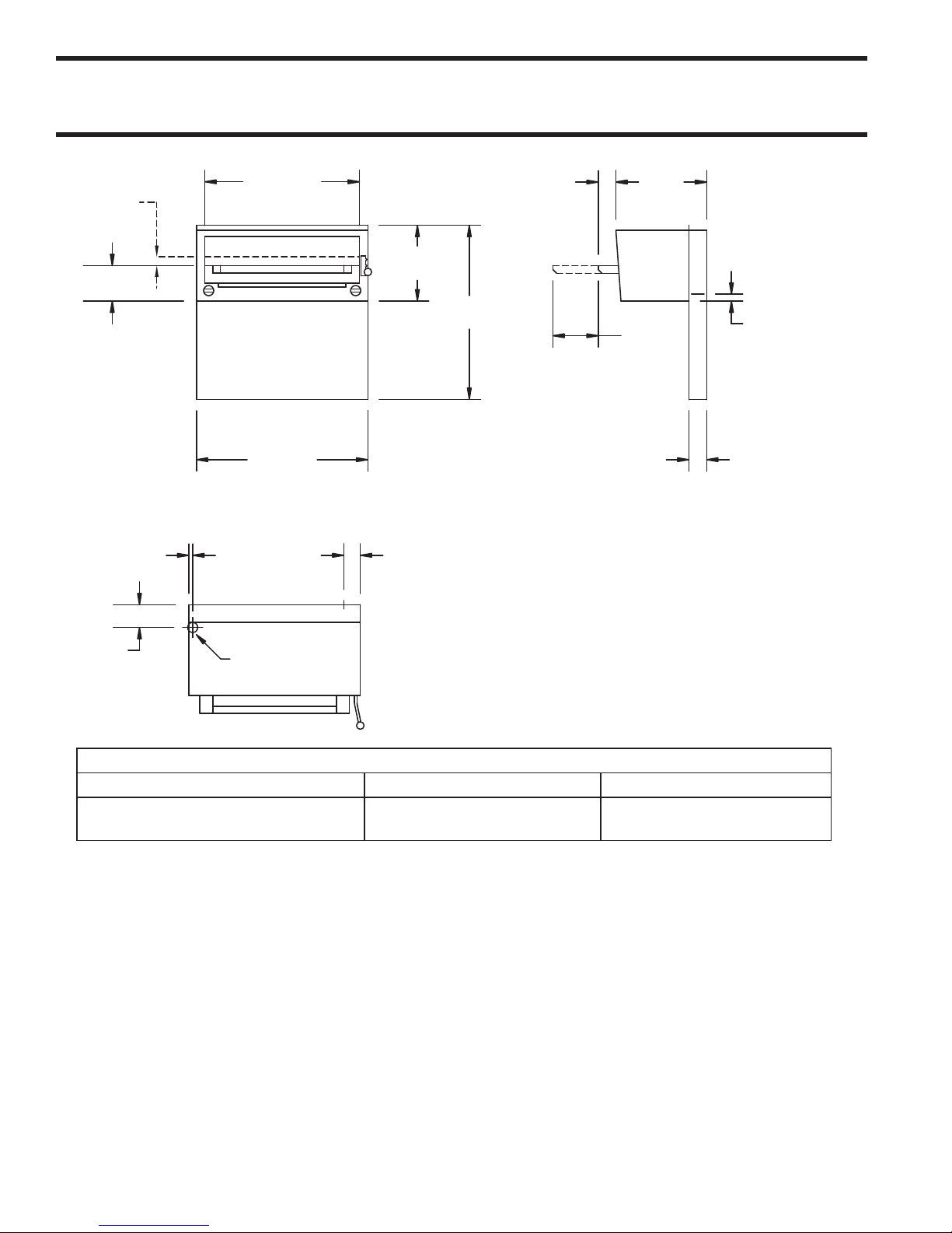
DIMENSIONS AND SPECIFICATIONS, MODEL MIR 34L
3-1/2"
[89mm]
18"
[457mm]
3-1/2"
[89mm]
9”
[229mm]
1-3/8"
[35mm]
REARGAS
INLETON
”W"&"C"
MODELS
¾"
[19mm]
4-1/2"
[114mm]
3-1/4"
[83mm]
REARGAS
INLETON
"W"&"C
MODELS
1/2"N.P.T.
[13mm]
TOPGAS
INLET
34"
[864mm]
15"
[381mm]
7"
[178mm]
1-3/4"
[44mm]
34-1/2"
[876mm]
30-11/16"
[779mm]
INSTALLATION NOTES
Combustible Wall Clearances ¹ Entry Clearances Operating Pressure
Sides: 6" (152mm)
Back: 6" (152mm)
¹NOTE: Installation clearance reductions are applicable only where local codes permit.
Crated: 39 3/4" (997mm)
Uncrated: 34-3/4" (870)
Natural: 6" WC (15mbar)
Propane: 11" WC (28mbar)
Data applies only to North America
Commercial cooking equipment requires an adequate ventilation system. For additional information, refer
to the National Fire Protection Association's standard NFPA96. (for North American only)
Gas input ratings shown here are for installations up to 2,000 ft. (610m) above sea level.
Specify altitudes over 2,000 ft.
Please specify gas type when ordering.
Part # 1382669 (07/05)Page 4
Page 5

DIMENSIONS AND SPECIFICATIONS, MODEL IR-280L SERIES
4-1/2"
1-3/4"
[44mm]
3-1/2"
[89mm]
1-3/8"
[35mm]
OPTIONAL
REAR
GAS
INLET
3-1/4"
[83mm]
OPTIONAL
REAR
GAS
INLET
1/2"N.P.T.
[83mm]
TOP
GAS
INLET
18"
[457mm]
1-3/4"
[45mm]
9"
[229mm]
34"
[864mm]
15"
[381mm]
15"
[381mm]
30"
[762mm]
36"
[914mm]
Model Width
IR36-280L 36" (914mm) H286 200/91 29" (737mm) 21" (533mm)
IR48-280L
IR60-280L
IR72-280L
(36" broiler + 12"/305mm flue riser w/shelf)
(36" broiler + 24"/610mm flue riser w/shelf)
(36" broiler + 36"/914mm flue riser w/shelf)
48"(1219mm)
60" (1524mm)
72" (1829mm)
Use With H280
Series Model
H288 230/105 29" (737mm) 21" (533mm)
H284 & H287 260/118 29" (737mm) 21" (533mm)
H289 280/127 29" (737mm) 21" (533mm)
Shipping Wt.
Lbs./Kgs.
Entry Clearances: In (mm)
Crated Uncrated
Note Salamander Broiler on Left Side. Right Side Optional
Operating Pressure Installation Clearances Total Input Orifice
Natural Propane Sides Rear
6"WC (15mbar) 11"WC (28mbar) 6"(152mm) 6"(152mm) #48F #55F
40,000 BTU/HR (11.7Kw)
NAT PRO
Gas input ratings shown for installations up to
2000 ft., (610m), above sea level.
Please specify altitudes over 2000 ft.
For use on noncombustible floors
Commercial cooking equipment requires an
adequate ventilation system. For additional
information, refer to the National Fire Protection
Association's standard NFPA96.
This product is not approved for residential use.
Part # 1382669 (07/05) Page 5
Page 6

DIMENSIONS AND SPECIFICATIONS, CHEESE MELTER
20"
[508mm]
17-3/8"
[441mm]
31-1/4"
[794mm]
8-3/8”
[213mm]
5-13/32"
[137mm]
3-1/2"
[89mm]
15-1/2"
[394mm]
37-3/8"
[949mm]
37-3/8"
[949mm]
15-1/2"
[394mm]
3-1/2"
[89mm]
2-1/4"
[57mm]
19"
[483mm]
2"
[51mm]
34"
[864mm]
1/2"N.P.T.[13mm]
TOPGASINLET
19"
483mm]
1/2"N.P.T.
[13mm]
TOPGAS
INLET
2-1/4"
[57mm]
2"
[51mm]
24"
[610mm]
17-3/8"
[441mm]
20"
[508mm]
5-13/32
[137mm]
8-3/8"
[213mm]
21-1/4"
[540mm]
Model Width Depth Height
GCM 24-280 24" (610,mm) 19" (483mm) 37-1/4" (946mm)
GCM 36-280 36" (314mm) 19" (483mm) 37-1/4" (946mm)
MCM 34 34" (864mm) 19" (483mm) 37-1/4" (946mm) 24"(610mm 20"(508mm)
Note: Data applies only to North America
Operating Pressure Installation Clearances Input: Natural and Propane Orifice
Natural Propane Sides Rear
6" WC (15 mbar) 11" WC (28 mbar) 6" (152mm) 6" (152mm)
NOTE: Installation clearance reductions are applicable
Model Shipping Wt. (Lbs./Kg)
GCM 34 180/82
GCM 36-280 180/82
GCM 60-280 220/100
GCM 72-280 240/109
only where local codes permit
Commercial cooking equipment requires an adequate
ventilation system. For additional information, refer to the
National Fire Protection Association's standard NFPA96.
Gas input ratings shown for installations up to 2000 ft.,
(610m), above sea level. Please specify altitudes over
2000 ft.
Please specify gas type when ordering.
This product is not approved for residential use
Entry Clearances: All Models
Crated Uncrated
15,000 BTU/Hr (4.39 Kw) per Burner
30,000 BTU/Hr (8.79 Kw) Total
Nat #50F
Pro #57F
Part # 1382669 (07/05)Page 6
Page 7

GENERAL INFORMATION
e range-mounted, gas Infra-Red Salamander Broiler
and Infra-Red Cheese Melter is designed as M Series
and H/P Series Models for perfect match and fit.
e range-mounted, gas Infra-Red Cheese Melter Broiler
is designed as Series and H/P Series Models for
perfect match and fit. Ideal for preparing melted cheese
dishes, casseroles, au gratin dishes, soufflés, Mexican
food and other ethnic foods.
Garland/U.S. Range products are not approved or
authorized for home or residential use, but are intended
for commercial applications only. Garland / U.S. Range
will not provide service, warranty, maintenance or support
of any kind other than in commercial applications.
Salamander Performance and Construction
Two Hi-Low gas valves provide individual control of the
() atmospheric-type , BUT gas infra-red burners
for the Salamander. “LO” position is adjustable for most
field gas pressure situations. Fast preheat and uniform
production is provided by the high-efficiency, infrared burners. Unique atmospheric design eliminates the
need for fans and filters. Heat is directed downward to
the large - square inch plus – heavy duty broiling
rack. Rack is easily removed from spring balanced rack
assembly. Rack assembly rolls out for ease of loading and
unloading. Rack assembly raises and lowers with positive
locking in three positions. Full-width grease deflector
attached to the underside of the rack assembly channels
hot drippings to a large capacity drain pan even when
rack assembly is rolled out. e rack assembly and drain
pan are easily removed for cleaning. e MIRL is ”
wide and is supported by heavy-formed brackets with
stainless steel back-splash. Front and sides of salamander
are stainless steel.
IR- is ” wide, supported by heavy-formed
brackets. Salamander front & back-splash is stainless
steel with black baked enamel sides.
IR-L has a finished width of ” which includes
a ” wide shelf. Salamander front and back-splash is
stainless steel with black baked enamel sides.
Cheese Melter
Performance and Construction
Twenty-four inch wide model has a single atmospheric
type, , BTU gas infra-red burner. irty-four and
thirty six inch wide models each have two () atmospheric
type, , BTU has infra-red burners. Burners are
individually controlled by three () position three ()
heat valves (HI, LO, OFF). Fast preheat and uniform
production is provided by the high-efficiency, infra-red
burners. Unique atmospheric design eliminates the need
for fans and filters. Heat is directed downward to the
large heavy chrome-plated rack. Sturdy chrome-plated
rack guides support the rack, which is adjustable to three
() positions. Rack and rack guides are easily removed
for cleaning.
H/P Series and Series range mounted cheese melters
are securely supported by heavy formed brackets.
H/P Series and Series cheese melters are standard
with stainless steel fronts. Backsplash and remainder of
exterior are finished in black baked enamel. Pressure
regulator is standard.
Rating Plate
When corresponding with the factory or your local
authorized factory service center regarding service
problems or replacement parts, be sure to refer to the
particular unit by the correct model number (including
the prefix and suffix letters and numbers) and the
warranty serial number. e rating plate affixed to the
unit contains this information.
We suggest installation, maintenance and repairs should
be performed by your local authorized service agency
listed in your information manual pamphlet.
In the event you have any questions concerning the
installation, use, care or service of the product, write or
call our Product Service Department.
is product has been certified as commercial cooking
equipment and must be installed by professional
personnel as specified.
Part # 1382669 (07/05) Page 7
Page 8

INSTALLATION
National Code Requirements
e importance of the proper installation of Commercial
Gas Cooking Equipment cannot be over stressed. Proper
performance of the equipment is dependent, in great
part, on the compliance of the installation with the
manufacturer’s specifications. Installation must conform
to local codes or, in the absence of local codes, with
the National Fuel code, ANSI Z., Natural Gas
Installation Code, CAN/GCA-B. or the Propane
Installation Code, CAN/CGA-B., as applicable.
Gas Connections
Before assembly and connection, check gas supply.
A. e type of gas for which the unit is equipped is
stamped on the data plate located on the lower front
frame, simply remove the drip pan for easy access.
Connect a unit stamped “NAT” only to natural
gas; connect those stamped “PRO” only to propane
gas.
B. If it is a new installation, have gas authorities
check meter size and piping to assure that the unit
is supplied with sufficient amount of gas pressure
required to operate the unit.
C. If it is additional equipment or replacement have
a qualified gas technician check the gas pressure
to make certain that existing gas facilities (meter
piping, etc.) will deliver the BTU’s of gas required
at the unit with no more than ½” water column
pressure drop. When checking pressure, be certain
that other equipment on the same gas line is on at
full rate.
NOTE: When checking pressure, be sure that all
other equipment on the same gas line is on. A pressure
regulator is supplied with Garland Infra-Red Broilers.
Regulator is preset at deliver gas at pressure shown on
the rating plate.
D. e appliance and its individual shut off (supplied
by others) must be disconnected from the gas supply
piping system during any pressure testing of that
system at pressures in excess of ½” psi (3.45 kPa).
E. e appliance must be isolated from the gas supply
piping system by closing its individual manual shut
off valve (supplied by others) during any pressure
testing of the gas supply piping system at test
pressures equal to or less than ½ psi (3.45 kPa).
F. Gas supply connection is made in back lower left
hand corner of unit. A readily accessible approved
type of hand valve should be installed on each
supply line. Test for leaks – DO NOT USE ANY
OPEN FLAME.
G. A pressure tap plug is supplied with the units and it
is installed on the manifold. e drip pan must be
removed to use the pressure tap. e gas pressure
must be checked when the unit is installed, to insure
that the unit gas pressure is the same as specified on
the rating plate. If necessary, pressure adjustments
must be made at the pressure regulator, supplied on
each Infra-Red Broiler.
NOTE: the pressure regulator is located at the top rear
of the salamander.
H. If it is completely new installation, have gas lines,
meter size piping and piping installed and checked
by a qualified gas technician.
I. Make certain that the new piping, joints and
connections have been made in a clean manner and
have been purged, so that the piping compound,
chips, etc, will not clog pilots, valves and/or
controls. Use pipe joint sealant that is resistant to
liquefied petroleum gas.
WARNING Check gas connections for leaks. Use a
soap solution or similar means. DO NOT USE AN
OPEN FLAME!
Note: is appliance is not recommended for residential
installation.
Pressure Regulators in Battery Installations
1. Must have a maximum regulation capacity for the
total connected load.
Part # 1382669 (07/05)Page 8
Page 9

INSTALLATION Continued
Upright
Burner Box
Side
1/4" x 3/4"
Type "B"
Washer Hex Head SMS
4 Req'd
~
1
"X"
"X"
2
8
4
3
6
7
5
GARL
AN
D
2. e pressure regulator(s) installed must be listed by
a nationally recognized agency.
3. e pressure regulator(s) must have a pressure
adjustment range to allow adjustment to the
manifold pressure on the appliance rating plate.
4. Unless the manifold pressure on all connected
appliances is the same, a separate regulator must
be supplied for each appliance(s) having different
manifold pressures.
5. Gas supply lines may be connected at right, left or
both ends of a battery or at the tee connections on
spreader plates. If five (5) or more units are placed
in a battery, more that one (1) supply line should
be used. A readily accessible, approved type of
hand shut off valve (supplied by others) should be
installed on each supply line.
CAUTION: Local codes may require that the pressure
regulator be externally vented. is is to be supplied by
others.
Assembly Instructions
Salamander/Cheese Melters
M-Series Salamanders/Cheese Melters
1. Remove front panel #5 by removing two (2) sheet
metal screws from under side of salamander/cheese
melter and pushing front panel downward.
2. With back panel #4 still attached to the left #2 and
right #3 uprights drop uprights into the rectangular
cutouts at the rear of the range
3. Fasten uprights #2 and #3 to the range #1 with four
(4) 5/16” -18 bolts and flat washers #6 and #7.
4. If unit is in a battery line up, fasten adjacent units
together at hole marked “X” with ¼” -20 bolts, nuts
and washers.
5. Install front panel #5 previously removed. Attach
front panel #5 to salamander/cheese melter with
two (2) sheet metal screws
Installation of Salamander to a Range
Model IR-L. GCM-. GCM-
1. e back of the range must be easily accessible
2. Position the salamander on rear of the range slipping
uprights into burner box sides.
3. Securely fasten using hardware shown.
Part # 1382669 (07/05) Page 9
Page 10

INSTALLATION Continued
Upright
Burner Box
Back
Stabilizer
Bracket
Mounting
Bracket
Mounting
Bracket
Top
Bottom
Upright
Burner
Box Side
Stabilizer
Bracket
1/4" x 3/4"
Type "B" Washer
Hex Head (8 Req'd
)
# 10 x 3/4"
Phillips Truss
Head
1/4" 20 x 3/4" Hex
Head Self Tapping
Screws (2 ea. Side)
&
1/4 x 2/4 Washer
(2 ea. Side)
End Support Bracket
Center Support
Use Existing # 10 Sheet Metal Screws
From Back Flange
Back Flange
Rear View
Remove Oven Flue for H/P288 Double Ovens Only
Models IR60-280L, GCM60-280
1. Back of range must be easily accessible.
2. Fasten mounting bracket to burner box back as
shown using four (4) of #10 x ½” type “A” truss
head SMS, Phillips.
3. Position salamander on rear of range slipping
uprights into burner box sides and mounting
bracket.
4. Make sure front panel is in front of stabilizer
bracket.
5. Securely fasten using hardware shown.
Models IR48-280L or GCM48-280 Mounting
to 48” Range with one Full Size Oven
Models IR48-280L IR72-280L,
GCM48-280, GCM72-280
1. Back of range must be easily accessible.
2. Position salamander on rear of range slipping
uprights into burner box sides.
3. Make sure front panel is in front of stabilizer bracket
on 72” range.
1. Back of range must be easily accessible.
2. If mounting to a double oven, remove oven flue
from left side looking at rear of unit.
3. Place salamander in place and fasten securely, using
hardware shown.
4. Re-install oven flue
4. Securely fasten hardware shown.
Part # 1382669 (07/05)Page 10
Page 11

INSTALLATION Continued
Wall Mounted Salamanders, Cheese Melters
or Counter Mounted Salamander or
Cheese Melters
1. Clearance from combustible construction must be
six inches (6’) minimum at rear and six inches (6”)
minimum at sides.
Each gas appliance shall be located with respect to
building construction and other equipment so as
to permit access to the appliance. Such access and
clearance my be necessary for service and cleaning.
2. All models ending with suffix “C” must be fastened
to the counter top.
3. All models ending with suffix “W” are mounted to
a vertical surface using the mounting kit as shown
below. e salamanders are shipped with the wall
mounting kit already attached to the appliance.
4. Provisions for gas connections, bottom or rear,
should be taken into consideration at time of
installation.
Ventilation and Air Supply
Proper ventilation is highly important for good operation.
e ideal method of ventilation a Salamander Broiler is
the use of a properly designed canopy hood which should
extend six inches (”) beyond all sides of the appliance
and six () feet six () inches from the floor.
A strong exhaust fan will create a vacuum in the room,
for an exhaust system to work properly, replacement air
must enter the room in which the vent is located. the
amount of air which is exhausted must equal the amount
entering, (make-up air).
All gas burners and pilots need sufficient air to operate
and large objects should not be placed in front or on top
of the broiler which would obstruct the air flow through
the front of the broiler.
FOR YOUR SAFETY never place any type of object
on top of the salamander broiler or cheese melters. e
top of the broiler will exceed º F. It could cause
severe burns or fire and obstruct ventilation
Clearances:
From Combustible material ” sides and rear. A clearance
of .” to non combustible construction as sides & rear
is acceptable, for the Salamander, e Cheese melter is
not suitable for installation on a combustible floor.
Part # 1382669 (07/05) Page 11
Page 12

OPERATION
Pilot Lighting Instructions
1. e in-line service shut-off valve should be in the
“ON” position.
2. With a lighted taper you can now light in the pilots
which are located at the rear of the main burner.
3. Pilot flame should be approximately 7/8” long for
proper ignition of the burners. e pilot adjustment
valve can be located by sliding the drip tray forward.
Adjustment valves are located on the manifold pipe
which runs horizontal across the back of the unit,
behind the drip tray, one is at the left rear and the
other at the right rear.
To adjust the pilot light, turn the brass screw
counter-clock-wise to increase the pilot flame, and
clock-wise to decrease the pilot flame.
NOTE: No more than /” pilot flame length should
be required. Too high a setting will cause the fame to
lift off or will create excessive carboning. Do not adjust
the pilot flame lower than /” long because this can
cause delayed ignition at the burner. e delayed ignition
could cause the burner tiles to crack; in that case the
burner would have to be replaced.
Main Burner Operation
Turn main burner knob to the “MAX” position
immediately check ignition.
Burn off Period
Many parts used in the manufacturing of commercial
equipment have a thin, protective coating of machine
oil. is oil should be burned off before the equipment
is used for food preparation.
After all start-up and safety checks have been completed,
turn burner valve to the “MAX” position. Smoke (a
bluish haze) will be produced. is process can take
several hours and can be completed over a few days
Energy Conservation
Do not waste energy by leaving controls at high
temperature settings during idle periods. Lower settings
will keep broiler warm and ready for next use period.
Reset burner valve knob as required for heavy load
periods
Shut Down Instructions
Turn main burner valve knobs to the “OFF” position.
If the unit is to be shut down for an extended period of
time, close the manual in-line service valve off, (manual
in-line service valve is not factory supplied).
FOR YOUR SAFETY never place any type of object on
top of the salamander broiler or cheese melters. e top
of the broiler will exceed º F. It could cause severe
burns and/or fire and also will obstruct ventilation.
CAUTION Should ignition fail after five seconds, turn
valve off and wait five minutes before trying again.
Pilot gas is not interrupted automatically. It is the
responsibility of the operator to check the ignition of
burners immediately after the burner valve has been
turned on.
When ignition has been accomplished, a blue flame will
cover the surface of the ceramics for - seconds. e
haze will disappear and the burner rod will glow red.
After the burners have operated for several minutes turn
the valve to “MIN.” e burner rods will no longer glow
red and the flame travels back and forth on the face of
the burner ceramics.
Main Burner Adjustments
All Salamanders are provided with a fixed burner orifices
to provide , BTU/HR at the “MAX” setting on
propane gas supplied at .” W/C. All Cheese Melters
are provided with a fixed burner orifices to provide
, BTU/HR at the “MAX” setting on natural gas
supplied at a .” W/C pressure and , BTU/HR
at the “MAX” setting on propane gas supplied at .”
W/C.
e “MIN” setting is adjustable and should be set as
follows:
1. Set the burner valve knob to “MIN” setting and
remove the knob.
Part # 1382669 (07/05)Page 12
Page 13

OPERATION Continued
2. Insert a thin bladed screwdriver into the valve stem
to engage the slot inside the stem. Turn clockwise
to decrease the rate and counter-clockwise to
increase.
Proper adjustment is attained at the point where the
burner rods no longer glow and the flame travels back
and forth on the face of the ceramics.
MAINTENANCE AND CLEANING
A program of proper cleaning techniques will aid in
continued trouble free operation of this or any quality
equipment
Daily
Grid racks should be wiped daily while still warm,
using a heavy cloth or other grease absorbing material
to remove grease and burnt food before they burn into
the grid. Remove burnt materials, such as carbonized
grease or food, with a stiff wire brush. DO NOT USE
ANY TYPE OF STEEL WOOL. Small particles may
be left on the grid surface and get into food products.
Grid racks should be washed thoroughly using a wire
brush and a hot, mild detergent or soap solution. Rinse
with clear, warm water.
Monthly
is adjustment has been factory pre-set, however, with
changing pressures this adjustment and pilot adjustment
may need to be re-done after installation.
is is not considered a manufacturing defect and is
not warrantable.
Exterior Cleaning
Establish a regular schedule. Any spills should be wiped
off immediately.
1. Wipe exposed, clean-able surface when cool with
a mild detergent and hot water. Stubborn residue
spots may be removed with a light weight nonmetallic scouring pad. Dry thoroughly with a clean
cloth.
2. Stainless steel should be cleaned using a mild
detergent, a soft cloth and hot water. If it is necessary
to use a non-metallic scouring pad, always rub in
the direction of the grain in the metal to prevent
scratching. Use a water based stainless steel cleaner
(such as Drackett Twinkle), if you want a high
shine.
Lubricate valves and bearings as required. Due to the
usual location of the broiler that is mounted above a
range with open tops, the heat from the open top will
cause the lubrication grease inside the valves to dry out.
When you notice that the valve is becoming harder to
turn it is then time to have them greased. We suggest
an Authorized Service Agent who is familiar with the
appliance and working with natural and propane gas,
to perform this type of work.
Part # 1382669 (07/05) Page 13
Page 14

NOTES
Part # 1382669 (07/05)Page 14
Page 15

NOTES
Part # 1382669 (07/05) Page 15
Page 16

 Loading...