

Page 1
INSTALLATION AND
OPERATION MANUAL
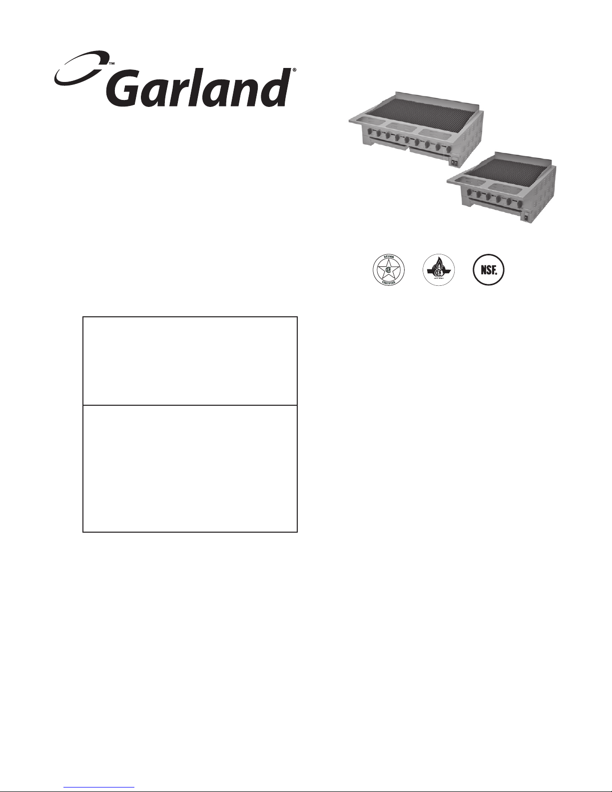
HEEG “CL”
HIGH EFFICIENCY
RADIANT CHAR-BROILER
FOR YOUR SAFETY:
DO NOT STORE OR USE GASOLINE
OR OTHER FLAMMABLE VAPORS OR
LIQUIDS IN THE VICINITY OF
THIS OR ANY OTHER
APPLIANCE
WARNING:
IMPROPER INSTALLATION, ADJUSTMENT,
ALTERATION, SERVICE OR MAINTENANCE
CAN CAUSE PROPERTY DAMAGE, INJURY,
OR DEATH. READ THE INSTALLATION,
OPERATING AND MAINTENANCE
INSTRUCTIONS THOROUGHLY
BEFORE INSTALLING OR
SERVICING THIS EQUIPMENT
PLEASE READ ALL SECTIONS OF THIS MANUAL
AND RETAIN FOR FUTURE REFERENCE.
THIS PRODUCT HAS BEEN CERTIFIED AS
COMMERCIAL COOKING EQUIPMENT AND
MUST BE INSTALLED BY PROFESSIONAL
PERSONNEL AS SPECIFIED.
IN THE COMMONWEALTH OF MASSACHUSETTS
THIS PRODUCT MUST BE INSTALLED BY A
LICENSED PLUMBER OR GAS FITTER.
For Your Safety:
Post in a prominent location, instructions to be
followed in the event the user smells gas. This
information shall be obtained by consulting
your local gas supplier.
Users are cautioned that maintenance and repairs must be performed by a Garland authorized service agent
using genuine Garland replacement parts. Garland will have no obligation with respect to any product that has been
improperly installed, adjusted, operated or not maintained in accordance with national and local codes or installation
instructions provided with the product, or any product that has its serial number defaced, obliterated or removed,
or which has been modified or repaired using unauthorized parts or by unauthorized service agents.
For a list of authorized service agents, please refer to the Garland web site at http://www.garland-group.com.
The information contained herein, (including design and parts specifications), may be superseded and is subject
to change without notice.
GARLAND COMMERCIAL INDUSTRIES, LCC
185 East South Street
Freeland, Pennsylvania 18224
Phone: (570) 636-1000
Fax: (570) 636-3903
Part # 4526671 (10/02/09) © 2009 Garland Commercial Industries, LCC.
GARLAND COMMERCIAL RANGES, LTD.
1177 Kamato Road, Mississauga, Ontario L4W 1X4
CANADA
Phone: 905-624-0260
Fax: 905-624-5669
Page 2

IMPORTANT INFORMATION
WARNING:
This product contains chemicals known to the state of california to cause cancer and/or birth defects
or other reproductive harm. Installation and servicing of this product could expose you to airborne
particles of glass wool/ceramic fibers. Inhalation of airborne particles of glass wool/ceramic fibers
is known to the state of california to cause cancer. Operation of this product could expose you to
carbon monoxide if not adjusted properly. Inhalation of carbon monoxide is known to the state of
california to cause birth defects or other reproductive harm.
Keep appliance area free and clear of combustibles.
Part # 4526671 (10/02/09)Page 2
Page 3

TABLE OF CONTENTS
IMPORTANT INFORMATION. . . . . . . . . . . . . . . . . . . . . . . . . . . . . . . . . . . . . . . . . . 2
DIMENSIONS AND SPECIFICATIONS CL MODELS . . . . . . . . . . . . . . . . . . . . . . 4
INTRODUCTION. . . . . . . . . . . . . . . . . . . . . . . . . . . . . . . . . . . . . . . . . . . . . . . . . . . . . 5
Rating Plate . . . . . . . . . . . . . . . . . . . . . . . . . . . . . . . . . . . . . . . . . . . . . . . . . . . . . . . . . . . . . . . . . . . . . .5
INSTALLATION . . . . . . . . . . . . . . . . . . . . . . . . . . . . . . . . . . . . . . . . . . . . . . . . . . . . . . 5
General Installation . . . . . . . . . . . . . . . . . . . . . . . . . . . . . . . . . . . . . . . . . . . . . . . . . . . . . . . . . . . . . .5
Stand Dimensions. . . . . . . . . . . . . . . . . . . . . . . . . . . . . . . . . . . . . . . . . . . . . . . . . . . . . . . . . . . . . . . .6
Clearances . . . . . . . . . . . . . . . . . . . . . . . . . . . . . . . . . . . . . . . . . . . . . . . . . . . . . . . . . . . . . . . . . . . . . . .6
Positioning and Setup . . . . . . . . . . . . . . . . . . . . . . . . . . . . . . . . . . . . . . . . . . . . . . . . . . . . . . . . . . . .6
Air Supply and Ventilation . . . . . . . . . . . . . . . . . . . . . . . . . . . . . . . . . . . . . . . . . . . . . . . . . . . . . . . .6
Gas Connection . . . . . . . . . . . . . . . . . . . . . . . . . . . . . . . . . . . . . . . . . . . . . . . . . . . . . . . . . . . . . . . . . .7
Manual Shut-O Valve . . . . . . . . . . . . . . . . . . . . . . . . . . . . . . . . . . . . . . . . . . . . . . . . . . . . . . . . . . .7
Pressure Regulator . . . . . . . . . . . . . . . . . . . . . . . . . . . . . . . . . . . . . . . . . . . . . . . . . . . . . . . . . . . . . . .7
Rigid Connections . . . . . . . . . . . . . . . . . . . . . . . . . . . . . . . . . . . . . . . . . . . . . . . . . . . . . . . . . . . . . . .7
Flexible Couplings & Connectors . . . . . . . . . . . . . . . . . . . . . . . . . . . . . . . . . . . . . . . . . . . . . . . . .7
Final Gas Connection Review . . . . . . . . . . . . . . . . . . . . . . . . . . . . . . . . . . . . . . . . . . . . . . . . . . . . .8
Start Up . . . . . . . . . . . . . . . . . . . . . . . . . . . . . . . . . . . . . . . . . . . . . . . . . . . . . . . . . . . . . . . . . . . . . . . . . 8
Shut Down . . . . . . . . . . . . . . . . . . . . . . . . . . . . . . . . . . . . . . . . . . . . . . . . . . . . . . . . . . . . . . . . . . . . . . 8
Final Preparation . . . . . . . . . . . . . . . . . . . . . . . . . . . . . . . . . . . . . . . . . . . . . . . . . . . . . . . . . . . . . . . . .8
CLEANING AND MAINTENANCE . . . . . . . . . . . . . . . . . . . . . . . . . . . . . . . . . . . . . . 9
Daily . . . . . . . . . . . . . . . . . . . . . . . . . . . . . . . . . . . . . . . . . . . . . . . . . . . . . . . . . . . . . . . . . . . . . . . . . . . .9
Periodic . . . . . . . . . . . . . . . . . . . . . . . . . . . . . . . . . . . . . . . . . . . . . . . . . . . . . . . . . . . . . . . . . . . . . . . . . 9
Cleaning Stainless Steel . . . . . . . . . . . . . . . . . . . . . . . . . . . . . . . . . . . . . . . . . . . . . . . . . . . . . . . . . .9
SERVICE AND PARTS . . . . . . . . . . . . . . . . . . . . . . . . . . . . . . . . . . . . . . . . . . . . . . . . 9
Part # 4526671 (10/02/09) Page 3
Page 4
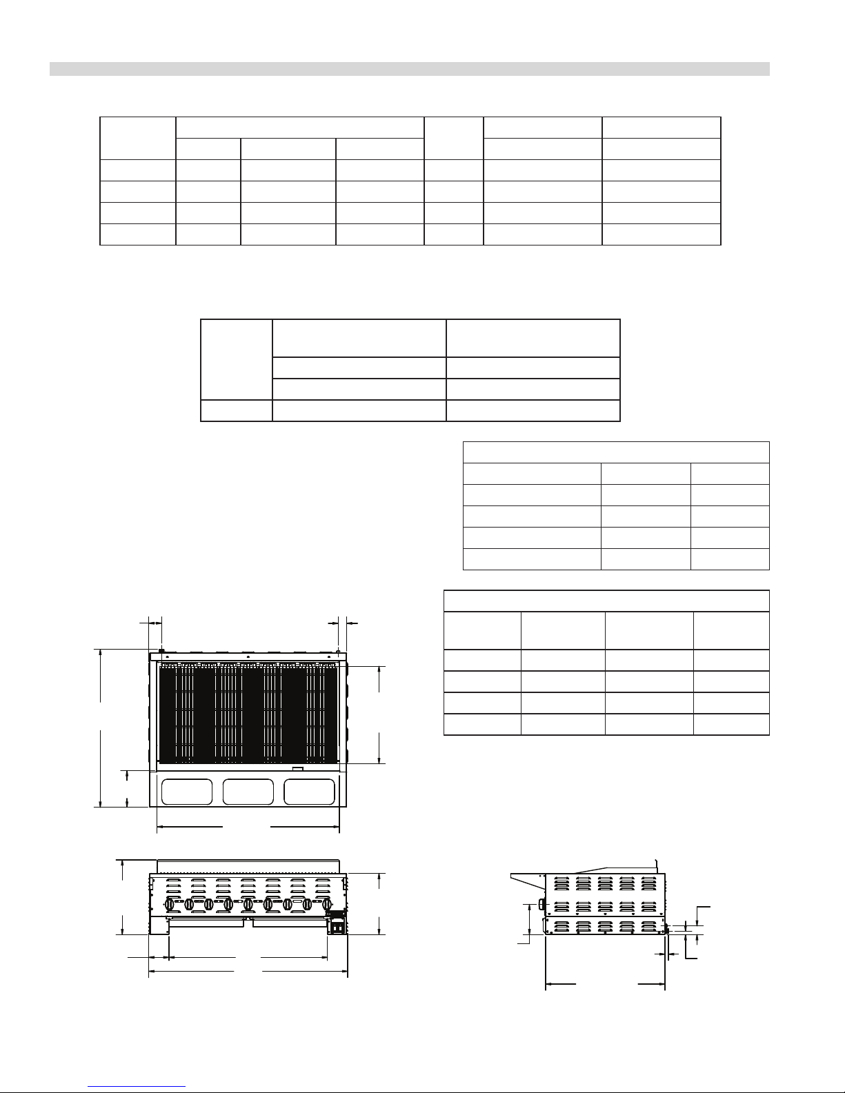
DIMENSIONS AND SPECIFICATIONS CL MODELS
HEEG-48CL BROILER SHOWN
GAS INLET
Model #
Dimensions: In. (mm)
Width Depth Height Natural Weight Lbs/Kg
No. Of
Burners
HEEG-24CL 24 (610) 38-1/16 (967) 18-1/16 (458) 4 54,000 338/153
HEEG-36CL 34 (864) 38-1/16 (967) 18-1/16( 458) 6 81,000 391/177
HEEG-48CL 48 (1219) 38-1/16(967) 18-1/16 (458) 9 121,500 505/229
HEEG-60CL 58 (1473) 38-1/16 (967) 18-1/16 (458) 11 148,500
* Manifold operating pressure as per table shown below
Gas Manifold 3/4" NPT on all models
Gas Input ratings shown here are for installations up to 2000 ft. (610m)
Manifold Operating
Pressure
Models
Natural Gas Natural Gas
"w.c.(Mbar) "w.c.(Mbar)
All Models 4.5 (11.2) 7.0(17.4)
Garland/U.S. Range products are not approved or authorized
for home or residential use, but are intended for commercial
applications only. Garland / U.S. Range will not provide service,
warranty, maintenance, or support of any kind other than in
commercial applications.
Many local codes exist and it is the responsibility of the
owner and installer to comply with those codes.
Total BTU* Shipping
620/281
Minimum Supply Pressure
Depth Measurements all models In (mm)
Front Rail Option Over All "A" Rail "B"
With/ 1/3 Pan Cutouts 38-1/16 (967) 8-7/8 (225)
With/1/9 Pan Cutouts 35-5/8 (905) 6-3/8 (162)
Std. Rail (No Cutouts) 34-5/8 (879) 5-3/8 (137)
Stub Rail (No Cutouts) 31-3/4 (806) 2-1/2 (64)
3-1/8"
[79mm]
3/4" NPT
GAS INLET
"A"
"B"
"C"
18-1/16"
[458mm]
4-7/8"
[123mm] "D"
"E"
2"
[51mm]
ELECTRICAL
23-1/2"
[596mm]
14-3/4"
[375mm]
Width Measurements In (mm)
Model
Broiler Grid
"C"
"D"
Over All
"E"
HEEG-24CL 20 (507) 14-1/4 (362) 24 (610)
HEEG-36CL 30 (761) 24-1/4 (616) 34 (864)
HEEG-48CL 44 (1117) 36-1/4 (972) 48 (1219)
HEEG-60CL 54 (1371) 48-1/4 (1226) 58 (1473)
Electrical : 120V, 60 Hz
Provided with NEMA 5-15P Power Cord Supply
NOTE: Wiring Diagram is located in right side of broiler’s
leg section.
2-1/16"
[53mm]
ELECTRICAL
7-1/8"
[185mm]
7/8"[22mm]
28-13/16"
[732mm]
13/16"
[21mm]
3/4"
Part # 4526671 (10/02/09)Page 4
Page 5

INTRODUCTION
Garland manufactures the HE Series char-broiler with widths
ranging from 24” (610mm) to 58” (1473mm). While service
and customer operation may vary from model to model,
installation is similar throughout the line.
All units are shipped completely assembled, with top grates
and radiants banded to skid in separate boxes, any loose
parts are secured in place with masking tape or tie cords,
and the pressure regulators packed inside the unit. All units
are adjusted, tested, and inspected at the factory prior to
shipment.
IMPORTANT: After uncrating, immediately check the
equipment for visible signs of shipping damage. If such
damage has occurred, do not refuse shipment, but contact
the shipper and le the appropriate freight claims.
There are two metal guide shipping brackets used to help
prevent the unit from sliding in the shipping crate. It is not
necessary to remove these brackets but if desired they are
located on the inside center support leg channels. Each
guide bracket is attached with two sheet metal screws. To
remove the brackets, rst remove the grease trays for easier
access and then loosen the screws. Once the screws are
loosen the brackets will slide o. Finally tighten the screws
back into the unit and replace the grease trays.
Rating Plate
The rating plate is attached to the front left inside broiler
channel leg support.
Information on this plate includes the model and serial
numbers. When communicating with the factory about a
unit or requesting special parts or information, this data is
essential for proper identication. Other information on this
plate is the BTU/hr input to the burners, outlet gas pressure
in inches WC, and whether oriced for natural or propane
gas.
In the event you have any questions concerning the
installation, use, care or service of the product, write or call
our Product Service Department.
WARNING: All Garland Char-Broilers must be connected only
to the type of gas identied on the rating plate!
INSTALLATION
General Installation
In European countries, installation must be carried out by
a competent person and in accordance with the relevant
regulations, codes of practice and the related publications of
the country of destination.
In the United States, the installation must conform to the
National Fuel Gas Code ANSI Z223.1, or latest edition, NFPA
No.54-latest edition/or local code to assure safe and ecient
operation. In Canada, the installation must comply with CSA
B149.1 and local codes.
CAUTION: This appliance is not recommended for residential
installation.
1. The type of gas for which the unit is equipped is stamped
on the rating plate. Connect a unit stamped “NAT” only to
natural gas; connect one stamped “PRO” only to propane
gas.
2. A manual gas shut-o valve must be installed in the gas
supply line ahead of the appliance for safety and for ease
of future service.
3. A gas pressure regulator must be installed at the appliance
prior to connecting the equipment to the gas line. This unit
is shipped with a regulator. Failure to install a regulator will
void the equipment warranty.
4. When mounting onto counter or optional HEST stand seal
the broiler to the at surface with silicone. A NSF code
requirement in many areas.
Part # 4526671 (10/02/09) Page 5
Page 6

INSTALLATION Continued
Stand Dimensions
Dimensions
Model
Number
HEST-24 24"(610mm) 39/18
HEST-36 34"(864mm) 55/25
HEST-48 48"(1219mm) 69/31
HEST-60 58"(1473mm) 77/35
1-7/8"
[48mm]
A (Width)
STOPS
29-5/16"
[746mm]
SIDE VIEW
A
Shipping
Weight
lb/kg
NONCOMBUSTIBLE
CONSTRUCTION
Rear 0”
Sides 0”
Positioning and Setup
Some form of mechanical assistance will be required to
position these broilers, as the smallest weighs 338 lbs
(153 kg) and the larger sizes weigh 620 lbs (281kg). A pallet
or lift jack will also make leveling easier, as these units are
designed to sit ush on a counter, do not have adjustable
legs or feet, and leveling is with shims and repeated tting.
Inside the unit, the char-broilers use cast tubular burners
with cast iron radiants, which are secured to the burner
hangers to stop vibration and damage during shipping Once
free, double-check that the burners are positioned squarely
in the notches of the back burner holder. If they are out of
position, the burner will not work properly.
Air Supply and Ventilation
The area around the appliance must be kept clear to avoid
any obstruction to the ow of combustion and ventilation
air, as well as, for ease of maintenance and service.
2"
[51mm]
SQUARE
TUBING LEGS
6"
[152mm]
FRONT VIEW
21"
[533mm]
Clearances
HE Series
The appliance area must be kept free and clear of all
combustibles. Adequate clearance must be provided for air
openings into the combustion chamber and for proper air
supply.
These units are design-certied for the following
installations:
1. Intended for other than household use.
2. For use in non-combustible locations only.
Means must be provided for any commercial, heavy-duty
cooking appliance to exhaust combustion waste products
to the outside of the building. This is doubly important for
open grate broilers, since the design promotes grease and fat
dripping through onto hot radiants sending smoke back up
onto the product as seasoning. This smoke then continues
either up to the ceiling or to an exhaust hood. Garland
Char-Broilers must be under a vent hood! Filters and drip
troughs should be part of any industrial hood, but consult
local codes before constructing and installing a hood.
Air movement should be checked during installation,
strong exhaust fans in the hood or in the overall system can
produce a vacuum in the room and/or cause air drafts. Either
of which can interfere with the burner performance and be
dicult to diagnose. If burner problems persist, make-up air
openings or baes may have to be provided in the room.
Any adjustments to air movement should be performed or
inspected by a qualied technical installer. Maintain and do
not block the appliances designed air openings.
Part # 4526671 (10/02/09)Page 6
Page 7

INSTALLATION Continued
Gas Connection
NOTE: The gas supply (service) line must be the same size or
greater than the inlet line of the appliance. Garland CharBroilers use a 3/4” NPT inlet. Sealant on all pipe joints must be
resistive to LP gas.
The appliance and its individual shut-o valve must be
disconnected from the gas supply piping system during any
pressure testing of that system at test pressures in excess of
1/2 psi (3.45 kPa).
The appliance must be isolated from the gas supply piping
system by closing its individual manual shut-o valve during
any pressure testing of the gas supply piping system at test
pressures equal to or less than 1/2 psi (3.45 kPa).
Manual Shut-O Valve
The Manual Shut-O Valve is supplied by the installer, it must
be installed in the gas service line ahead of the appliance
and regulator in the gas stream and in a position where it can
be reached quickly in the event of an emergency.
Pressure Regulator
Regulators can be adjusted in the eld, but it is
recommended that they not be tampered with unless that
part is known to be out of adjustment or serious pressure
uctuations are found to exist and can be solved no other
way. Any adjustments to regulators must be made by
qualied service personnel with the proper test equipment.
If a vent line from the gas appliance pressure regulator is
used, it should be installed to the outdoors in accordance
with local codes.
In North America in the absence of local codes, in accordance
with the National Fuel code, ANSI Z223.1, Natural Gas
Installation Code, CAN/CGA-B149.1 or the Propane
Installation Code, CAN/CGA-B149.2, as applicable.
WARNING: Failure to install a pressure regulator will void the
equipment warranty!
Rigid Connections
Double-check any installer-supplied intake pipes visually
and clear any dirt particles, threading chips, or other foreign
matter before installing in a service line. Those particles will
clog orices when gas pressure is applied.
All heavy-duty, commercial cooking equipment must have
a pressure regulator in the incoming service line for safe and
ecient operation, since service pressure may uctuate with
local demand. The manual shut-o valve is normally supplied
by the installer, but pressure regulators are shipped from
Garland with every Char-Broiler.
Regulators are pre-set at the factory according to the
customer’s ordering instructions. It is important to check and
adjust regulator to manifold operating pressure as per rating
plate.
Prior to connecting the regulator, check the incoming line
pressure, as these regulators can withstand a maximum
pressure of 1/2 psi (14” WC). If the Line pressure is beyond
this limit, a step-down regulator will be required. Doublecheck the arrow forged onto the bottom of the regulator
body which shows gas ow directions; it should point
downstream to the appliance. The red air-vent cap is part of
the regulator and should not be removed unless local codes
require external venting.
Flexible Couplings & Connectors
If the unit is to be installed with exible couplings and/or
quick disconnect ttings, for an appliance equipped with
stand and casters, the installation shall be made with a heavy
duty design-certied commercial exible connector or at
least 3/4” NPT (with suitable strain relief) in compliance with
all local authorities and codes.
In North America connection must be in compliance with the
Standard for Connectors for Moveable Gas Appliances, ANSI
Z21.69/CSA 6.16, Addenda Z21.69B-2006/CSA 6.16B-2006 (or
latest edition), and a quick-disconnect device that complies
with the Standard for Quick Disconnects for Use with Gas
Fuel, ANSI Z21.41/CSA 6.9, Addenda Z21.41A-2005/CSA
6.16A-2005 (or latest edition), and adequate means must be
provided to limit the movement of the appliance without
depending on the connector and the quick-disconnect
device or its associated piping to limit the appliance
movement and the location(s) where the restraining means
may be attached to the appliance shall be specied.
Part # 4526671 (10/02/09) Page 7
Page 8

INSTALLATION Continued
Further, if the unit is to be installed on a non-combustible
surface that is equipped with casters, means must be
provided to limit the movement of the unit with casters.
Final Gas Connection Review
Check all gas connections for leaks using a soapy solution
before lighting any pilots! DO NOT USE AN OPEN FLAME
TO CHECK FOR LEAKS! Putting an open ame beside a new
connection is not only dangerous, but will often miss small
leaks that a soapy solution would nd.
All Garland appliances are adjusted and tested before
leaving the factory, eectively matching them to sea
level conditions. Adjustments and calibrations to assure
proper operation may be necessary on installation to meet
local conditions, low gas pressure, dierences in altitude,
variations in gas characteristics, to correct possible problems
caused by rough handling or vibration during shipment, and
are to be performed only by qualied service personnel.
These adjustments are the responsibility of the customer,
installer and/or dealer and are not covered by the Garland
warranty.
All burners are equipped with continuous electronic spark
electrodes to insure ame is on at all times during operation.
Continuous sparking is intended to remain energized until
power is manually switched o.
WARNING: All connections must be sealed with a joint
compound suitable for LP gas, and all connections must be
tested with a soapy solution before lighting any pilots!
For daily start up:
1. Models HEEG-24CL and HEEG-36CL have one power
switch. Once pushed to the “ON” position an igniter
supplies a continuous spark to the burners igniting the
gas to all burners simultaneously. At the same time the
power switch opens up the gas ow to burners.
2. Models HEEG-48CL and HEEG-60CL have two power
switches which operate in the same manner as the
single switch above. Each switch operates separately
allowing the operator to run two sections of the broiler
independently. On the HEEG-48CL the switch on the far
left operates burners 1 to 5. The power switch on the
right will operate burners 6 to 9. On the HEEG-60CL the
left switch controls burners 1 to 6 and the right switch
controls burners 7 to 11.
3. If burners do not ignite, shutdown power to the unit,
and wait 5 minutes before repeating ignition. If repeated
ignition fails, shutdown power to the unit and contact a
service person.
Shut Down
1. For shutting down overnight, on all models turn the
power switch(es) to the “OFF” position.
2. When shutting down for longer periods, turn the power
switch(es) to the “OFF” position and turn the manual
supply shut o valve to the “OFF” position.
Final Preparation
Start Up
Before initial lighting or if unit does not operate at all check
to see if:
1. Main gas supply shut o to appliance is open.
2. Electric power supply power and cord Nema 5-15P has
been plug into an appropriate 120V 15Amp 60Hz outlet.
New units are wiped clean with solvent at the factory to
remove any visible signs of dirt, oil, grease, etc., remaining
from the manufacturing process. They should be washed
with hot, soapy water to remove any solvent or oil residue or
installation dust or debris before using for food preparation.
Part # 4526671 (10/02/09)Page 8
Page 9

CLEANING AND MAINTENANCE
Any piece of equipment works better and lasts longer when
maintained properly and kept clean. Cooking equipment is
no exception. Your Garland Char-Broiler must be kept clean
during the working day and thoroughly cleaned at the end
of each day.
WARNING: If gas odors are detected, the gas supply must
be turned “OFF” at the main shut-o valve and the local gas
company or authorized service agency contacted for service.
NOTE: A wire brush is supplied with your broiler for cleaning
your rack. The solid stainless steel tooth side of the brush is
for hard to remove debris and the reverse wire bristles side is
for ner materials.
Daily
NOTE: Never Place A Sheet Pan Or Other Large Obstruction
Over The Grates When Broiler Is Hot.
1. Remove the broiler grates. Wire brush them clean of
any encrusted materials and wash in hot, soapy water. A
common cleaning practice is to turn grates upside-down
to burn o encrusted material. Do not do this with the
radiant char-broiler! The ame from the burner is shielded
by a cast iron radiant, with the result that heat not ame
reaches the grate. It is likely that cooked-on-matter will
cook in even deeper rather than burn o.
2. Remove the radiants and wire brush them clean, then
wash in hot soapy water. A rule of thumb is that if the
grates are becoming encrusted, so are the radiants.
3. Spills should be wiped as they occur. At the end of the
day drip tray pans should be washed in hot soapy water,
replacing the trays once cleaned. DO NOT operate the
broiler with out the drip trays.
Periodic
Your Garland Char-Broiler should be checked and adjusted
periodically by qualied service personnel as part of a regular
kitchen maintenance program.
Cleaning Stainless Steel
All stainless steel body parts should be wiped regularly with
hot, soapy water during the day, and with a liquid cleaner
designed for this material at the end of each day. Do not
use steel wool, abrasive cloths, cleaners, or powders! If it
is necessary to scrape stainless steel to remove encrusted
materials, soak the encrusted area with wet cloths to loosen
the material, then use a wood or nylon scraper. Do not use
a metal knife, spatula, or any other metal tools to scrape
stainless steel. Scratches are almost impossible to remove.
SERVICE AND PARTS
Installation, maintenance and repairs should be performed
by your local authorized Garland service agency listed in
your information manual pamphlet.
Garland/U.S. Range products are not approved or authorized
for home or residential use, but are intended for commercial
applications only. Garland / U.S. Range will not provide
service, warranty, maintenance or support of any kind other
than in commercial applications.
Part # 4526671 (10/02/09) Page 9
Page 10

WIRING DIAGRAMS
WHITE
-
JS
SIZE
B
APP.
DR. CK.
2009
06/03
DOC DATE DR APP
2166
PCO-
BLACK
GREEN
BLACK
34
#4
See Note 2
33
32
31
#12#2 #3
GREEN
GND
BLACK
1
3
BLUE
24
L1N
BLACK
20 19
BLUE
3
20
CHANGE DESCRIPTION
RELEASED ITEM
SYM
REV
0 -
*** CAD PRODUCED DRAWING - DO NOT REVISE MANUALLY ***
BLUE
1
2009 GARLAND COMMERCIAL INDUSTRIES
C
THESE DRAWINGS AND SPECIFICATIONS ARE THE PROPERTY OF GARLAND COMMERCIAL INDUSTRIES
5
SW1
n/a
SCALE FACTOR
18224
FREELAND
PENNSYLVANIA
AND SHALL NOT BE COPIED OR REPRODUCED WITHOUT THEIR WRITTEN PERMISSION.
6
(EXCEPT AS NOTED)
TOLERANCE IN INCHES
(ANGULAR ± .5°)
DR. BY
DATE
(FLAT .XXX ± .015)(FORM .XXX ± .031)
DESCRIPTION
FILE NAMEMODEL(S)
WIRE DIAGRAM,
HEE(E/G) BROILER,
4525617-1
24CL
HEE(E/G)
24" , 120VAC
ORANGE (TYP)
USE WITH WIRE PKG 4525624-11 -
USE WAGO (773-104) F580 4 WIRE PUSH-IN (GCR #F580 GCI# 4525593)2 -
NOTES: UNLESS OTHERWISE SPECIFIED
3
4
49
47
48
1
50
IGNITION MODULE
IGNITION MODULE
I
BLACK
0
ON
OFF
See Note 2
POWER SWITCH
BOTTOM VIEW
72
71
BLACK
BLUE
See Note 2
BLACK
82
86
BLUE
83
87
BLACK
BLUE
TO
SOLENOID VALVE
SOL2
SOL1
SOLENOID VALVE
USE FROM
SERIAL No.
Part # 4526671 (10/02/09)Page 10
Page 11

WIRING DIAGRAMS Continued
-
JS
SIZE
B
APP.
DR. CK.
03/23
DOC DATE DR APP
2166 2009
PCO-
WHITE
BLACK
GREEN
BLACK
35
36
#5
#6
32
33
34
#4
31
#1
#2 #3
GREEN
GND
BLACK
1
3
BLUE
24
L1N
BLACK
20 19
BLUE
20
CHANGE DESCRIPTION
RELEASED ITEM0 -
SYM
REV
2009 GARLAND COMMERCIAL INDUSTRIES
C
THESE DRAWINGS AND SPECIFICATIONS ARE THE PROPERTY OF GARLAND COMMERCIAL INDUSTRIES
*** CAD PRODUCED DRAWING - DO NOT REVISE MANUALLY ***
n/a
SCALE FACTOR
18224
FREELAND
PENNSYLVANIA
AND SHALL NOT BE COPIED OR REPRODUCED WITHOUT THEIR WRITTEN PERMISSION.
BLUE
5
SW1
1
(EXCEPT AS NOTED)
TOLERANCE IN INCHES
6
(ANGULAR ± .5°)
DR. BY
DATE
(FLAT .XXX ± .015)(FORM .XXX ± .031)
DESCRIPTION
WIRE DIAGRAM,
FILE NAMEMODEL(S)
4525618-1
HEE(E/G)
36" , 120VAC
HEE(E/G) BROILER,
36CL
ORANGE (TYP)
USE WAGO (773-104) F580 4 WIRE PUSH-IN (GCR #F580 GCI# 4525593)2 -
1 - USE WITH WIRE PKG 4525625-1
NOTES: UNLESS OTHERWISE SPECIFIED
1
6
54
46
45
47
2 3
48
49
50
IGNITION MODULE
I
BLACK
0
ON
OFF
See Note 2
POWER SWITCH
BOTTOM VIEW
74
73
BLACK
BLUE
See Note 2
SOL2
BLACK
86
87
SOL1
BLACK
TO
SOLENOID VALVE
USE FROM
SERIAL No.
83
BLUE
SOLENOID VALVE
82
BLUE
Part # 4526671 (10/02/09) Page 11
Page 12

WIRING DIAGRAMS Continued
DO NOT CONNECT
INPUT AT UNUSED
51
GREEN
GROUND UNUSED TERMINALS
BLACK (TYP)
65
TERMINALS
#5
#6
6
ORANGE
(TYP)
63
64
#4
54
46
GREEN
-
62
61
#1
#2 #3
24
GND
2 3
L1N
21
22
1
IGNITION MODULE 2
WHITE
BLACK
GREEN
03/23PCO-
DOC DATE DR APP
2166 2009
1
3
SIZE
SCALE FACTOR
FREELAND
PENNSYLVANIA
B
18224
n/a
(ANGULAR ± .5°)
(EXCEPT AS NOTED)
(FLAT .XXX ± .015)(FORM .XXX ± .031)
APP.
DR. CK.
FILE NAMEMODEL(S)
DR. BY
DATE
4525619-1
48CL,
HEE(E/G)
CHANGE DESCRIPTION
DESCRIPTION
TOLERANCE IN INCHES
WIRE DIAGRAM,
17
HEE(E/G) BROILER
48", 120VAC
BLACK
21
SYM
REV
18
2009 GARLAND COMMERCIAL INDUSTRIES
C
THESE DRAWINGS AND SPECIFICATIONS ARE THE PROPERTY OF GARLAND COMMERCIAL INDUSTRIES
AND SHALL NOT BE COPIED OR REPRODUCED WITHOUT THEIR WRITTEN PERMISSION.
*** CAD PRODUCED DRAWING - DO NOT REVISE MANUALLY ***
80
5
50
47
34
BLACK (TYP)
49
48
0 RELEASED- MC
BLUE
BLUE
GREEN
23
23
32
33
31
GND
L1N
#4
#12#2 #3
BLACK
19
22
20
78
BLUE
See Note 2
6
79
3
BLACK
BLACK
See Note 2
BLUE
NOTES: UNLESS OTHERWISE SPECIFIED
(GCR #F580 GCI# 4525593)
2 - USE WAGO (773-104) F580 4 WIRE PUSH-IN
1 - USE WITH WIRE PKG 4525626-1
3
4
ORANGE
(TYP)
43
42
See Note 2
82
BLUE
(SOL 1, IGNITION MODULE 1)
(SOL 2, IGNITION MODULE 2)
3 - (4) BURNERS ON LEFT MANIFOLD
4 - (5) BURNERS ON RIGHT MANIFOLD
1
IGNITION MODULE 1
1
45
44
BLACK
BLUE
78
BLUE
84
88
SOL1A
SOLENOID VALVE
See Note 2
79
BLACK
89
BLACK
85
86
BLUE
SOL1B
82
BLUE
BLACK
83
SOL2A
BLACK
80
See Note 2
87
BLACK
BLUE
SOL2B
SW2 (RIGHT)
18
13
BLACK
BLACK
SW1 (LEFT)
POWER SWITCH
BLUE
17
13
6
I
0
ON
OFF
TO
USE FROM
SERIAL No.
Part # 4526671 (10/02/09)Page 12
Page 13

WIRING DIAGRAMS Continued
DO NOT CONNECT
INPUT AT UNUSED
51
GREEN
GROUND UNUSED TERMINALS
BLACK (TYP)
65
TERMINALS
#6
6
ORANGE
(TYP)
BLACK (TYP)
36
#6
#5
54
46
n/a
(ANGULAR ± .5°)
(EXCEPT AS NOTED)
(FLAT .XXX ± .015)(FORM .XXX ± .031)
APP.
DR. CK.
FILE NAMEMODEL(S)
DR. BY
DATE
4525620-1
60CL,
HEE(E/G)
GREEN
62
63
64
#4
61
#1
#2 #3
24
GND
2 3
L1N
1
21
22
IGNITION MODULE 2
WHITE
BLACK
GREEN
JS -RELEASED ITEM0 -
07/20
DOC DATE DR APP
2166 2009
PCO-
1
3
SIZE
SCALE FACTOR
FREELAND
PENNSYLVANIA
B
18224
CHANGE DESCRIPTION
DESCRIPTION
TOLERANCE IN INCHES
WIRE DIAGRAM,
17
60", 120VAC
HEE(E/G) BROILER,
BLACK
21
SYM
REV
18
2009 GARLAND COMMERCIAL INDUSTRIES
C
THESE DRAWINGS AND SPECIFICATIONS ARE THE PROPERTY OF GARLAND COMMERCIAL INDUSTRIES
AND SHALL NOT BE COPIED OR REPRODUCED WITHOUT THEIR WRITTEN PERMISSION.
*** CAD PRODUCED DRAWING - DO NOT REVISE MANUALLY ***
80
5
50
47
33
35
34
#5
#4
49
48
BLUE
BLACK
BLUE
GREEN
23
32
#2 #3
23
31
GND
#1
L1N
BLACK
19
22
20
78
BLUE
See Note 2
6
BLACK
79
3
See Note 2
BLUE
6
40
ORANGE
(TYP)
NOTES: UNLESS OTHERWISE SPECIFIED
2 - USE WAGO (773-104) F580 4 WIRE PUSH-IN
1 - USE WITH WIRE PKG 4525627-1
54
41
42
See Note 2
82
BLUE
(GCR #F580 GCI# 4525593)
3 - (6) BURNERS ON LEFT MANIFOLD SOL 1, IGNITION MODULE 1)
4 - (5) BURNERS ON RIGHT MANIFOLD (SOL 2, IGNITION MODULE 2)
1
1
2 3
44
43
BLUE
78
BLUE
84
45
SOLENOID VALVE
IGNITION MODULE 1
BLACK
88
85
BLUE
SOL1A
BLACK
BLACK
80
See Note 2
See Note 2
79
89
BLACK
SOL1B
82
BLUE
BLACK
87
86
BLACK
BLUE
83
SOL2A
SOL2B
SW2 (RIGHT)
18
13
BLACK
BLACK
SW1 (LEFT)
POWER SWITCH
BLUE
17
13
6
I
0
ON
OFF
TO
USE FROM
SERIAL No.
Part # 4526671 (10/02/09) Page 13
Page 14

Part # 4526671 (10/02/09)Page 14
Page 15

Part # 4526671 (10/02/09) Page 15
Page 16

 Loading...