

INSTALLATION AND
OPERATION MANUAL
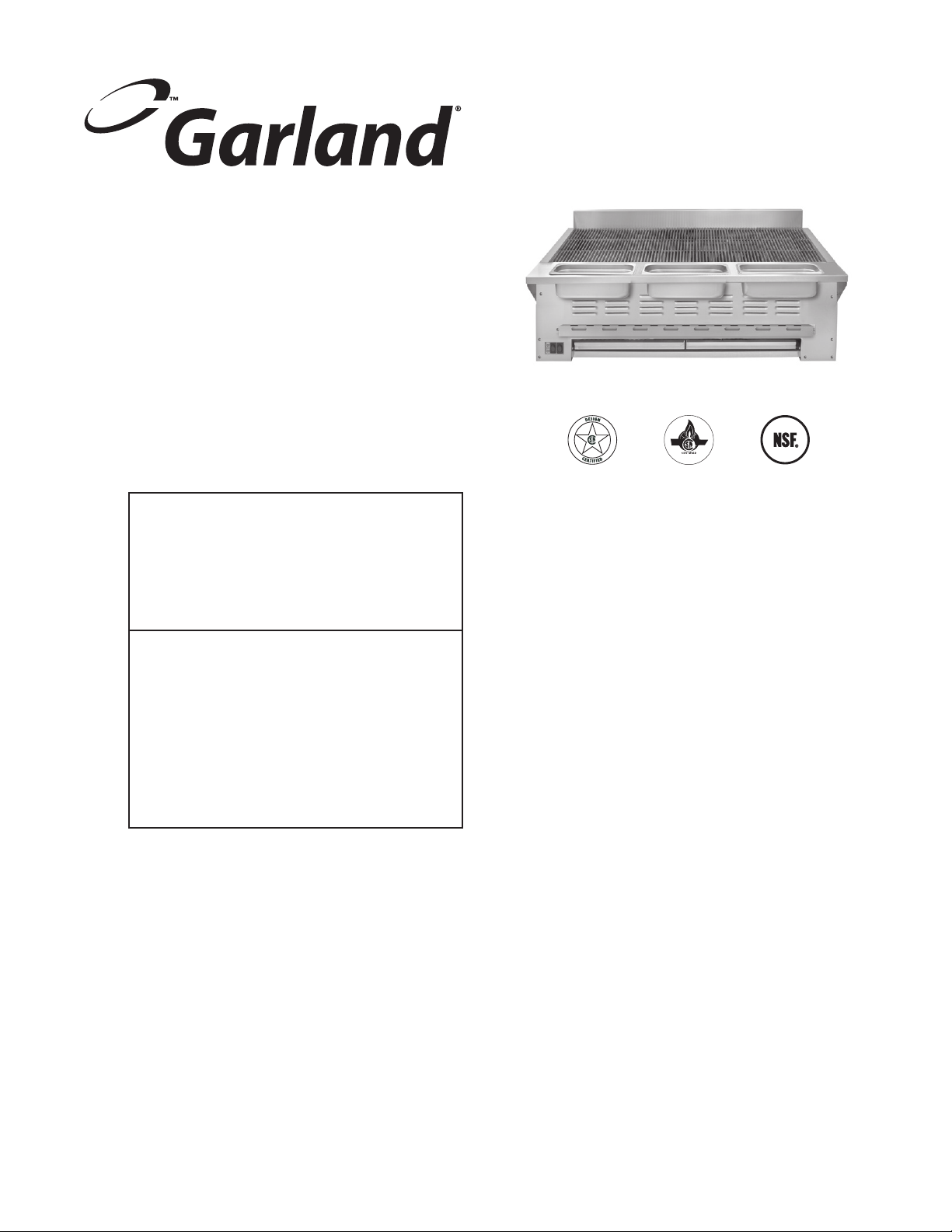
HE SERIES HIGH EFFICIENCY
RADIANT CHAR-BROILER
Français . . . . . . . . . . . . . . . . . . . . . . . . . . . . . . . . . . . . . . . . . . . . . . . . Page 11
Españo. . . . . . . . . . . . . . . . . . . . . . . . . . . . . . . . . . . . . . . . . . . . . . . Página 21
FOR YOUR SAFETY:
DO NOT STORE OR USE GASOLINE
OR OTHER FLAMMABLE VAPORS OR
LIQUIDS IN THE VICINITY OF
THIS OR ANY OTHER
APPLIANCE
WARNING:
IMPROPER INSTALLATION, ADJUSTMENT,
ALTERATION, SERVICE OR MAINTENANCE
CAN CAUSE PROPERTY DAMAGE, INJURY,
OR DEATH. READ THE INSTALLATION,
OPERATING AND MAINTENANCE
INSTRUCTIONS THOROUGHLY
BEFORE INSTALLING OR
SERVICING THIS EQUIPMENT
PLEASE READ ALL SECTIONS OF THIS MANUAL
AND RETAIN FOR FUTURE REFERENCE.
THIS PRODUCT HAS BEEN CERTIFIED AS
COMMERCIAL COOKING EQUIPMENT AND
MUST BE INSTALLED BY PROFESSIONAL
PERSONNEL AS SPECIFIED.
IN THE COMMONWEALTH OF MASSACHUSETTS
THIS PRODUCT MUST BE INSTALLED BY A
LICENSED PLUMBER OR GAS FITTER.
For Your Safety:
Post in a prominent location, instructions to be
followed in the event the user smells gas. This
information shall be obtained by consulting
your local gas supplier.
Users are cautioned that maintenance and repairs must be performed by a Garland authorized service agent
using genuine Garland replacement parts. Garland will have no obligation with respect to any product that has been
improperly installed, adjusted, operated or not maintained in accordance with national and local codes or installation
instructions provided with the product, or any product that has its serial number defaced, obliterated or removed,
or which has been modified or repaired using unauthorized parts or by unauthorized service agents.
For a list of authorized service agents, please refer to the Garland web site at http://www.garland-group.com.
The information contained herein, (including design and parts specifications), may be superseded and is subject
to change without notice.
GARLAND COMMERCIAL INDUSTRIES, LCC
185 East South Street
Freeland, Pennsylvania 18224
Phone: (570) 636-1000
Fax: (570) 636-3903
Part # 4522970 Rev 1 (10/28/09) © 2007 Garland Commercial Industries,LCC..
GARLAND COMMERCIAL RANGES, LTD.
1177 Kamato Road, Mississauga, Ontario L4W 1X4
CANADA
Phone: 905-624-0260
Fax: 905-624-5669
IMPORTANT INFORMATION
WARNING:
This product contains chemicals known to the state of california to cause cancer and/or birth defects
or other reproductive harm. Installation and servicing of this product could expose you to airborne
particles of glass wool/ceramic fibers. Inhalation of airborne particles of glass wool/ceramic fibers
is known to the state of california to cause cancer. Operation of this product could expose you to
carbon monoxide if not adjusted properly. Inhalation of carbon monoxide is known to the state of
california to cause birth defects or other reproductive harm.
Keep appliance area free and clear of combustibles.
Part # 4522970 Rev 1 (10/28/09)Page 2

TABLE OF CONTENTS
IMPORTANT INFORMATION. . . . . . . . . . . . . . . . . . . . . . . . . . . . . . . . . . . . . . . . . . 2
DIMENSIONS AND SPECIFICATIONS . . . . . . . . . . . . . . . . . . . . . . . . . . . . . . . . . . 4
INTRODUCTION. . . . . . . . . . . . . . . . . . . . . . . . . . . . . . . . . . . . . . . . . . . . . . . . . . . . . 5
Rating Plate . . . . . . . . . . . . . . . . . . . . . . . . . . . . . . . . . . . . . . . . . . . . . . . . . . . . . . . . . . . . . . . . . . . . . .5
INSTALLATION . . . . . . . . . . . . . . . . . . . . . . . . . . . . . . . . . . . . . . . . . . . . . . . . . . . . . . 5
General Installation . . . . . . . . . . . . . . . . . . . . . . . . . . . . . . . . . . . . . . . . . . . . . . . . . . . . . . . . . . . . . .5
Clearances . . . . . . . . . . . . . . . . . . . . . . . . . . . . . . . . . . . . . . . . . . . . . . . . . . . . . . . . . . . . . . . . . . . . . . .5
Positioning and Setup . . . . . . . . . . . . . . . . . . . . . . . . . . . . . . . . . . . . . . . . . . . . . . . . . . . . . . . . . . . .6
Air Supply and Ventilation . . . . . . . . . . . . . . . . . . . . . . . . . . . . . . . . . . . . . . . . . . . . . . . . . . . . . . . .6
Gas Connection . . . . . . . . . . . . . . . . . . . . . . . . . . . . . . . . . . . . . . . . . . . . . . . . . . . . . . . . . . . . . . . . . .6
Manual Shut-O Valve . . . . . . . . . . . . . . . . . . . . . . . . . . . . . . . . . . . . . . . . . . . . . . . . . . . . . . . . . . .6
Pressure Regulator . . . . . . . . . . . . . . . . . . . . . . . . . . . . . . . . . . . . . . . . . . . . . . . . . . . . . . . . . . . . . . .6
Rigid Connections . . . . . . . . . . . . . . . . . . . . . . . . . . . . . . . . . . . . . . . . . . . . . . . . . . . . . . . . . . . . . . .7
Flexible Couplings & Connectors . . . . . . . . . . . . . . . . . . . . . . . . . . . . . . . . . . . . . . . . . . . . . . . . .7
Manual Pilot Valve . . . . . . . . . . . . . . . . . . . . . . . . . . . . . . . . . . . . . . . . . . . . . . . . . . . . . . . . . . . . . . .7
Start Up . . . . . . . . . . . . . . . . . . . . . . . . . . . . . . . . . . . . . . . . . . . . . . . . . . . . . . . . . . . . . . . . . . . . . . . . .7
Shut Down . . . . . . . . . . . . . . . . . . . . . . . . . . . . . . . . . . . . . . . . . . . . . . . . . . . . . . . . . . . . . . . . . . . . . .7
CLEANING AND MAINTENANCE . . . . . . . . . . . . . . . . . . . . . . . . . . . . . . . . . . . . . . 8
Daily . . . . . . . . . . . . . . . . . . . . . . . . . . . . . . . . . . . . . . . . . . . . . . . . . . . . . . . . . . . . . . . . . . . . . . . . . . . .8
Periodic . . . . . . . . . . . . . . . . . . . . . . . . . . . . . . . . . . . . . . . . . . . . . . . . . . . . . . . . . . . . . . . . . . . . . . . . .8
Cleaning Stainless Steel . . . . . . . . . . . . . . . . . . . . . . . . . . . . . . . . . . . . . . . . . . . . . . . . . . . . . . . . . .8
Final Preparation . . . . . . . . . . . . . . . . . . . . . . . . . . . . . . . . . . . . . . . . . . . . . . . . . . . . . . . . . . . . . . . . . 8
SERVICE AND PARTS . . . . . . . . . . . . . . . . . . . . . . . . . . . . . . . . . . . . . . . . . . . . . . . . 9
Part # 4522970 Rev 1 (10/28/09) Page 3
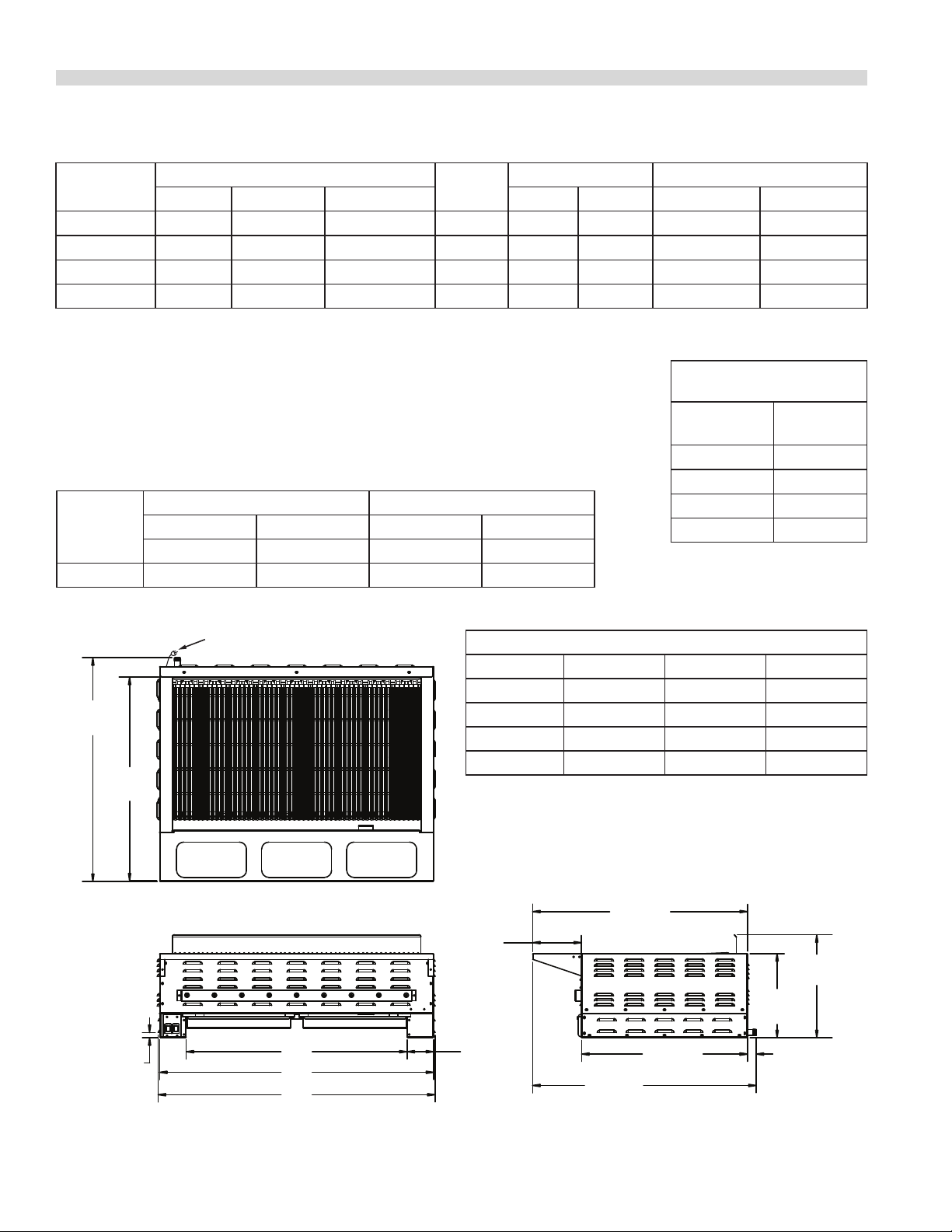
DIMENSIONS AND SPECIFICATIONS
Model #
Dimensions: In. (mm)
Width Depth Height Natural Propane Width Depth
No. Of
Burners
Total BTU* Gas Broiling Grid: In. (mm)
HEEE-24CL 24(610) 37-1/4(946) 17-13/16(453) 4 54,000 50,000 20-1/8 (511) 23-1/2(597)
HEEE-36CL 34(864) 37-1/4(946) 17-13/16(453) 6 70,000 72,000 30-1/8(765) 23-1/2(597)
HEEE-48CL 48(1219) 37-1/4(946) 17-13/16(453) 9 105,000 105,000 44-1/8(1121) 23-1/2(597)
HEEE-60CL 58(1473) 37-1/4(946) 17-13/16(453) 11 115,000 138,000 54-1/8(1375) 23-1/2(597)
* Manifold operating pressure as per table shown below
Gas Manifold 3/4" NPT on all model
Garland/U.S. Range products are not approved or authorized for home or residential use,
but are intended for commercial applications only.
Garland / U.S. Range will not provide service, warranty, maintenance, or support of any
kind other than in commercial applications.
Many local codes exist and it is the responsibility of the owner and installer to comply
with those codes.
HEEE-24CL 338/153
SHIPPING
INFORMATION
MODEL
Weight
Lbs/Kg
HEEE-36CL 391/177
Models
Manifold Operating Pressure Minimum Supply Pressure
Natural Gas Propane Natural Gas Propane
HEEE-48CL 505/229
HEEE-60CL 620/281
"w.c(Mbar) "w.c.(Mbar) "w.c.(Mbar) "w.c.(Mbar)
All Models 4.0(10) 10.0(25) 5.0(12.5) 11(27.5)
38.75"
[978mm]
[897mm]
[23mm]
35.30"
.91"
ELECTRIC CORD CONNECTION
A
B
C
Width Measurements In (mm)
Model A B C
HEEE-24CL 14.28 (363) 23.50 (597) 24.00 (610)
HEEE-36CL 24.38 (721) 33.50 (851) 34.00 (864)
HEEE-48CL 38.28 (972) 47.50 (1206) 48.00 (1219)
HEEE-60CL 48.28 (1226) 57.50 (1460) 58.00 (1473)
Electrical : 120V, 60 Hz 15 Amp
Supplied with NEMA 5-15 P Power Cord
NOTE: Wiring Diagram is located in right side of broiler’s leg
section.
37.25"
8.47"
[215mm]
4.61"
[112mm]
[946mm]
38.75"
[984mm]
28.71"
[729mm]
17.84"
[453mm]
14.58"
[370mm]
1.50"
[38mm]
Part # 4522970 Rev 1 (10/28/09)Page 4

INTRODUCTION
Garland manufactures the HE Series char-broiler with widths
ranging from 24” (610mm) to 58” (1473mm). While service
and customer operation may vary from model to model,
installation is similar throughout the line.
All units are shipped completely assembled, with top grates
and radiants banded to skid in separate boxes, any loose
parts are secured in place with masking tape or tie cords,
and the pressure regulators (and ceramic coals, if applicable)
packed inside the unit. All units are adjusted, tested, and
inspected at the factory prior to shipment.
IMPORTANT: After uncrating, immediately check the
equipment for visible signs of shipping damage. If such
damage has occurred, do not refuse shipment, but contact
the shipper and le the appropriate freight claims.
INSTALLATION
Rating Plate
The rating plate is attached to the front left inside broiler
channel leg support.
Information on this plate includes the model and serial
numbers. When communicating with the factory about a
unit or requesting special parts or information, this data is
essential for proper identication. Other information on this
plate is the BTU/hr input to the burners, outlet gas pressure
in inches WC, and whether oriced for natural or propane
gas.
In the event you have any questions concerning the
installation, use, care or service of the product, write or call
our Product Service Department.
WARNING: All Garland Char-Broilers must be connected only
to the type of gas identied on the rating plate!
General Installation
IMPORTANT: Safe and satisfactory operation of your
equipment depends, to a great extent, on its proper
installation. Installation must conform to local codes or, in
the absence of local codes with the National Fuel Code, ANSI
Z223.1 Natural Gas Installation Code, CAN/CGA –B149.1,
or the Propane Installation Code, CAN/CGA-B149.2, as
applicable.
1. Installation of the equipment should be made by a
licensed plumber.
2. A manual gas shut-o valve must be installed in the gas
supply line ahead of the appliance for safety and for ease
of future service.
3. A gas pressure regulator must be installed at the appliance
prior to connecting the equipment to the gas line. This unit
is shipped with a regulator. Failure to install a regulator will
void the equipment warranty.
4. When mounting onto counter or optional HEST stand seal
the broiler to the at surface with silicone. A NSF code
requirement in many areas.
Clearances
HE Series
The appliance area must be kept free and clear of all
combustibles. Adequate clearance must be provided for air
openings into the combustion chamber and for proper air
supply.
These units are design-certied for the following
installations:
1. Intended for other than household use.
2. For use in non-combustible locations only.
COMBUSTIBLE
CONSTRUCTION
Rear 6” (152mm) Rear 0”
Sides 6” (152mm) Sides 0”
NONCOMBUSTIBLE
CONSTRUCTION
Part # 4522970 Rev 1 (10/28/09) Page 5

INSTALLATION Continued
Positioning and Setup
Some form of mechanical assistance will be required to
position these broilers, as the smallest weighs 338 lbs
(153 kg) and the larger sizes weigh 620 lbs (281kg). A pallet
or lift jack will also make leveling easier, as these units are
designed to sit ush on a counter, do not have adjustable
legs or feet, and leveling is with shims and repeated tting.
Inside the unit, the char-broilers use cast tubular burners
with cast iron radiants, which are secured to the burner
hangers to stop vibration and damage during shipping Once
free, double-check that the burners are positioned squarely
in the notches of the back burner holder. If they are out of
position, the burner will not work properly.
Air Supply and Ventilation
The area around the appliance must be kept clear to avoid
any obstruction to the ow of combustion and ventilation
air, as well as, for ease of maintenance and service.
Means must be provided for any commercial, heavy-duty
cooking appliance to exhaust combustion waste products
to the outside of the building. This is doubly important for
open grate broilers, since the design promotes grease and fat
dripping through onto hot radiants sending smoke back up
onto the product as seasoning. This smoke then continues
either up to the ceiling or to an exhaust hood. Garland
Char-Broilers must be under a vent hood! Filters and drip
troughs should be part of any industrial hood, but consult
local codes before constructing and installing a hood.
Air movement should be checked during installation,
strong exhaust fans in the hood or in the overall system can
produce a vacuum in the room and/or cause air drafts. Either
of which can interfere with the burner performance and be
dicult to diagnose. If burner problems persist, make-up air
openings or baes may have to be provided in the room.
Any adjustments to air movement should be performed or
inspected by a qualied technical installer. Maintain and do
not block the appliances designed air openings.
The appliance must be isolated from the gas supply piping
system by closing its individual manual shut-o valve during
any pressure testing of the gas supply piping system at test
pressures equal to or less than 1/2 psi (3.45 kPa).
Manual Shut-O Valve
The Manual Shut-O Valve is supplied by the installer, it must
be installed in the gas service line ahead of the appliance
and regulator in the gas stream and in a position where it can
be reached quickly in the event of an emergency.
Pressure Regulator
All heavy-duty, commercial cooking equipment must have
a pressure regulator in the incoming service line for safe and
ecient operation, since service pressure may uctuate with
local demand. The manual shut-o valve is normally supplied
by the installer, but pressure regulators are shipped from
Garland with every Char-Broiler.
Regulators are pre-set at the factory for 4”WC (natural gas)
or 10”WC (propane) according to the customer’s ordering
instructions. Adjust regulator to manifold operating pressure
as per rating plate.
Prior to connecting the regulator, check the incoming line
pressure, as these regulators can withstand a maximum
pressure of 1/2 psi (14” WC). If the Line pressure is beyond
this limit, a step-down regulator will be required. Doublecheck the arrow forged onto the bottom of the regulator
body which shows gas ow directions; it should point
downstream to the appliance. The red air-vent cap is part of
the regulator and should not be removed unless local codes
require external venting.
Regulators can be adjusted in the eld, but it is
recommended that they not be tampered with unless that
part is known to be out of adjustment or serious pressure
uctuations are found to exist and can be solved no other
way. Any adjustments to regulators must be made by
qualied service personnel with the proper test equipment.
Gas Connection
NOTE: The gas supply (service) line must be the same size or
greater than the inlet line of the appliance. Garland CharBroilers use a 3/4” NPT inlet. Sealant on all pipe joints must be
resistive to LP gas.
The appliance and its individual shut-o valve must be
disconnected from the gas supply piping system during any
pressure testing of that system at test pressures in excess of
1/2 psi (3.45 kPa).
If a vent line from the gas appliance pressure regulator is
used, it should be installed to the outdoors in accordance
with local codes or, in the absence of local codes, with the
National Fuel code, ANSI Z223.1, Natural Gas Installation
Code, CAN/CGA-B149.1 or the Propane Installation Code,
CAN/CGA-B149.2, as applicable.
WARNING: Failure to install a pressure regulator will void the
equipment warranty!
Part # 4522970 Rev 1 (10/28/09)Page 6

INSTALLATION Continued
Rigid Connections
Double-check any installer-supplied intake pipes visually
and clear any dirt particles, threading chips, or other foreign
matter before installing in a service line. Those particles will
clog orices when gas pressure is applied.
Flexible Couplings & Connectors
If the unit is to be installed with exible couplings and/or
quick-disconnect ttings, for an appliance equipped with
casters, the installation shall be made with a heavy duty, AGA
design-certied commercial exible connector or at least
3/4” NPT (with suitable strain relief) in compliance with the
Standard for Connectors for Moveable Gas Appliances, ANSI
Z21.69/CSA 6.16, Addenda Z21.69B-2006/CSA 6.16B-2006 (or
latest edition), and a quick-disconnect device that complies
with the Standard for Quick Disconnects for Use with Gas
Fuel, ANSI Z21.41/CSA 6.9, Addenda Z21.41A-2005/CSA
6.16A-2005 (or latest edition), and adequate means must be
provided to limit the movement of the appliance without
depending on the connector and the quick-disconnect
device or its associated piping to limit the appliance
movement and the location(s) where the restraining means
may be attached to the appliance shall be specied.
All burners are equipped with continuous electronic spark
electrodes to insure ame is on at all times during operation.
Continuous sparking is intended to remain energized until
power is manually switched o.
WARNING: All connections must be sealed with a joint
compound suitable for LP gas, and all connections must be
tested with a soapy solution before lighting any pilots!
Start Up
Before initial lighting or if unit does not operate at all check
to see if:
1. Main gas supply shut o to appliance is open.
2. Electric power supply power and cord Nema 5-15P has
been plug into an appropriate 120V 15Amp 60Hz outlet.
For daily start up:
1. Models HEEE-24CL and HEEE-36CL have one power
switch. Once pushed to the “ON” position an igniter
supplies a continuous spark to the burners igniting the
gas to all burners simultaneously. At the same time the
power switch opens up the gas ow to burners.
Further, if the unit is to be installed on a non-combustible
surface that is equipped with casters, means must be
provided to limit the movement of the unit with casters.
Manual Pilot Valve
Check all gas connections for leaks using a soapy solution
before lighting any pilots! DO NOT USE AN OPEN FLAME
TO CHECK FOR LEAKS! Putting an open ame beside a new
connection is not only dangerous, but will often miss small
leaks that a soapy solution would nd.
All Garland appliances are adjusted and tested before
leaving the factory, eectively matching them to sea
level conditions. Adjustments and calibrations to assure
proper operation may be necessary on installation to meet
local conditions, low gas pressure, dierences in altitude,
variations in gas characteristics, to correct possible problems
caused by rough handling or vibration during shipment, and
are to be performed only by qualied service personnel.
These adjustments are the responsibility of the customer,
installer and/or dealer and are not covered by the Garland
warranty.
2. Models HEEE-48CL and HEEE-60CL have two power
switches which operate in the same manner as the
single switch above. Each switch operates separately
allowing the operator to run two sections of the broiler
independently. On the HEEE-48CL the switch on the far
left operates burners 1 to 5. The power switch on the
right will operate burners 6 to 9. On the HEEE-60CL the
left switch controls burners 1 to 6 and the right switch
controls burners 7 to 11.
3. If burners do not ignite, shutdown power to the unit,
and wait 5 minutes before repeating ignition. If repeated
ignition fails, shutdown power to the unit and contact a
service person.
4. Your broiler is an energy saving unit, all burners are preset at the factory to run at a consistent steady ame. No
adjustment should be attempted by the operator.
Shut Down
1. For shutting down overnight, on all models turn the
power switch(es) to the “OFF” position.
Part # 4522970 Rev 1 (10/28/09) Page 7
INSTALLATION Continued
2. When shutting down for longer periods, turn the power
switch(es) to the “OFF” position and turn the manual
supply shut o valve to the “OFF” position.
CLEANING AND MAINTENANCE
Any piece of equipment works better and lasts longer when
maintained properly and kept clean. Cooking equipment is
no exception. Your Garland Char-Broiler must be kept clean
during the working day and thoroughly cleaned at the end
of each day.
WARNING: If gas odors are detected, the gas supply must
be turned “OFF” at the main shut-o valve and the local gas
company or authorized service agency contacted for service.
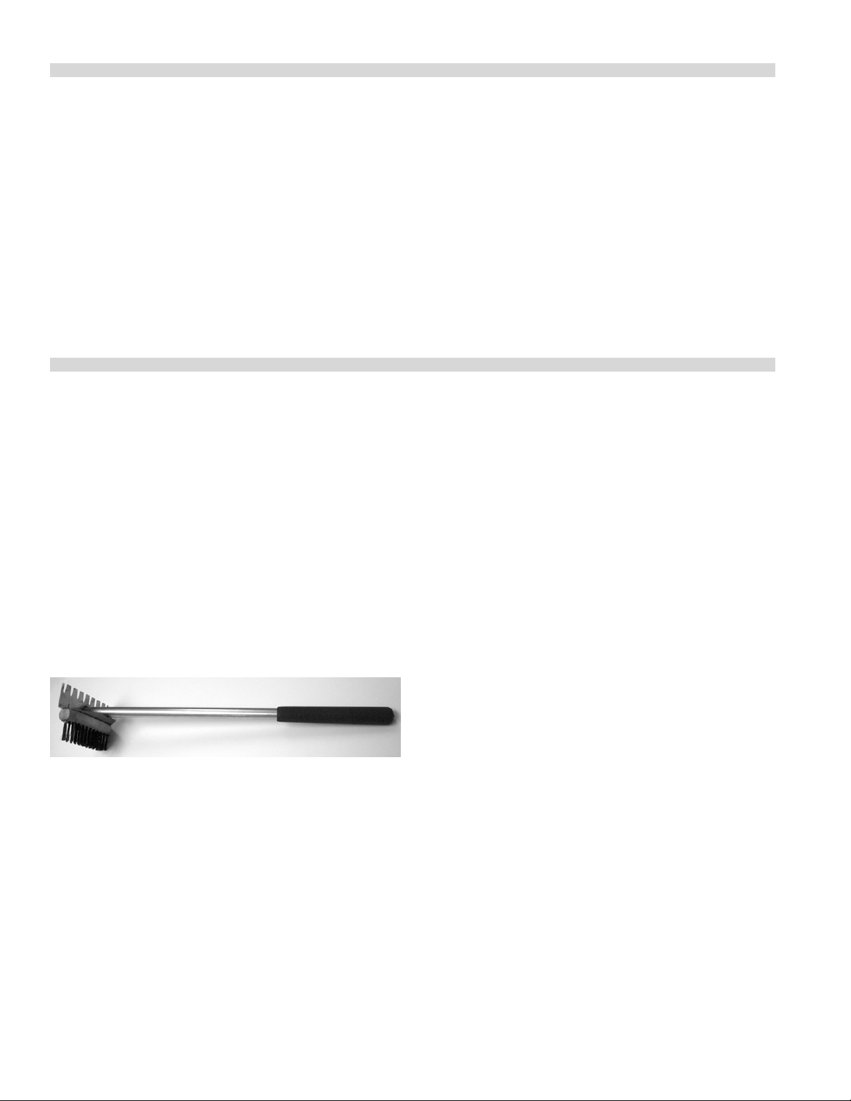
NOTE: A wire brush is supplied with your broiler for cleaning
your rack. The solid stainless steel tooth side of the brush is
for hard to remove debris and the reverse wire bristles side is
for ner materials.
Final Preparation
New units are wiped clean with solvent at the factory to
remove any visible signs of dirt, oil, grease, etc., remaining
from the manufacturing process. They should be washed
with hot, soapy water to remove any solvent or oil residue or
installation dust or debris before using for food preparation.
2. Remove the radiants and wire brush them clean, then
wash in hot soapy water. A rule of thumb is that if the
grates are becoming encrusted, so are the radiants.
3. Spills should be wiped as they occur. At the end of the
day drip tray pans should be washed in hot soapy water,
replacing the trays once cleaned. DO NOT operate the
broiler with out the drip trays.
Periodic
Your Garland Char-Broiler should be checked and adjusted
periodically by qualied service personnel as part of a regular
kitchen maintenance program.
Daily
1. Remove the broiler grates. Wire brush them clean of
any encrusted materials and wash in hot, soapy water. A
common cleaning practice is to turn grates upside-down
to burn o encrusted material. Do not do this with the
radiant char-broiler! The ame from the burner is shielded
by a cast iron radiant, with the result that heat not ame
reaches the grate. It is likely that cooked-on-matter will
cook in even deeper rather than burn o.
Cleaning Stainless Steel
All stainless steel body parts should be wiped regularly with
hot, soapy water during the day, and with a liquid cleaner
designed for this material at the end of each day. Do not
use steel wool, abrasive cloths, cleaners, or powders! If it
is necessary to scrape stainless steel to remove encrusted
materials, soak the encrusted area with wet cloths to loosen
the material, then use a wood or nylon scraper. Do not use
a metal knife, spatula, or any other metal tools to scrape
stainless steel. Scratches are almost impossible to remove.
Part # 4522970 Rev 1 (10/28/09)Page 8

SERVICE AND PARTS
Installation, maintenance and repairs should be performed
by your local authorized Garland service agency listed in
your information manual pamphlet.
Garland/U.S. Range products are not approved or authorized
for home or residential use, but are intended for commercial
applications only. Garland / U.S. Range will not provide
service, warranty, maintenance or support of any kind other
than in commercial applications.
Part # 4522970 Rev 1 (10/28/09) Page 9

Part # 4522970 Rev 1 (10/28/09)Page 10

MANUEL D’UTILISATION ET
D’INSTALLATION
LE GRIL TYPE CHARBON DE
BOIS HAUTE EFFICACITE
SERIE HE
POUR VOTRE SÉCURIT:
NE PAS STOCKER NI UTILISER D’ESSENCE
OU D’AUTRES VAPEURS OU LIQUIDES
INFLAMMABLES À PROXIMITÉ DE CET
APPAREIL OU DE TOUT AUTRE APPAREIL
MANUEL ET LE CONSERVER POUR S’Y REPORTER
ULTÉRIEUREMENT.
CE PRODUIT A ÉTÉ HOMOLOGUÉ EN TANT
QU’ÉQUIPEMENT PROFESSIONNEL DE CUISSON
ET DOIT ÊTRE INSTALLÉ PAR DU PERSONNEL
PROFESSIONNEL TEL QUE SPÉCIFIÉ.
LIRE TOUTES LES SECTIONS DU PRÉSENT
AVERTISSEMENT
UNE INSTALLATION, DES RÉGLAGES, DES
MODIFICATIONS, DES RÉPARATIONS OU UN
ENTRETIEN MAL FAITS PEUVENT CAUSER
DES DOMMAGES MATÉRIELS, DES BLES-
SURES OU LA MORT. LIRE SOIGNEUSEMENT
LES INSTRUCTIONS D’INSTALLATION,
D’UTILISATION ET D’ENTRETIEN
AVANT D’INSTALLER OU DE RÉPARER
L’ÉQUIPEMENT.
L’attention des utilisateurs est attirée sur le fait que l’entretien et les réparations doivent être e ectués par un agent
d’entretien autorisé par Garland utilisant des pièces de rechange d’origine Garland. Garland n’aura aucune obligation
en ce qui concerne n’importe quel produit mal installé, réglé, utilisé ou qui n’aurait pas été entretenu conformément aux
codes nationaux et locaux ou aux instructions d’installation fournies avec le produit ou n’importe quel produit dont le
numéro de série aurait été mutilé, oblitéré ou supprimé ou qui aurait été modi é ou réparé avec des pièces non autorisées
ou par des agents d’entretien non autorisés. Pour obtenir la liste des agents de service autorisés, consulter le site web
de Garland à : http://www.garland-group.com. Les renseignements contenus dans le présent document (y compris la
conception et les spéci cations des pièces) peuvent être remplacés ou modi és sans préavis.
DANS L’ÉTAT DU MASSACHUSETTS, CE PRODUIT
DOIT ÊTRE INSTALLÉ PAR UN PLOMBIER OU UN
MONTEUR D’INSTALLATION AU GAZ.
Pour votre sécurité
Placer dans un endroit bien en vue les instructions à suivre en cas d’odeur de gaz détectée par
l’utilisateur. Cette information peut être obtenue
auprès du fournisseur de gaz local
.
GARLAND COMMERCIAL INDUSTRIES, LLC
185 East South Street
Freeland, Pennsylvanie 18224
Téléphone : (570) 636-1000
Télécopieur : (570) 636-3903
Pièce n° 4522970 Rev 1 (10/28/09) © 2007 Garland Commercial Industries, LLC
GARLAND COMMERCIAL RANGES, LTD.
1177 Kamato Road, Mississauga, Ontario L4W 1X4
CANADA
Téléphone : 905-624-0260
Télécopieur : 905-624-5669

INFORMATIONS IMPORTANTES
AVERTISSEMENT
Ce produit contient des produits chimiques reconnus par l’état de Californie comme causant
le cancer et/ou des malformations congénitales ou d’autres problèmes de reproduction.
L’installation et l’entretien de ce produit peut vous exposer aux poussières de laine de
verre/fibres céramiques. L’inhalation de ces particules de laine de verre ou de fibres céramiques
est reconnue par l’état de Californie comme causant le cancer. L’utilisation de ce produit peut vous
exposer au monoxyde de carbone en cas de mauvais réglage. L’inhalation de monoxyde de carbone
est reconnue par l’état de Californie comme pouvant causer des malformations congénitales ou
d’autres problèmes reproductifs.
Maintenir les abords de l’appareil
dégagés et ne pas y stocker de produits combustibles
Pièce nº 4522970 Rev 1 (10/28/09)Page 12

TABLE DES MATIÈRES
INFORMATIONS IMPORTANTES . . . . . . . . . . . . . . . . . . . . . . . . . . . . . . . . . . . . . 12
DIMENSIONS ET SPÉCIFICATIONS . . . . . . . . . . . . . . . . . . . . . . . . . . . . . . . . . . .14
INTRODUCTION. . . . . . . . . . . . . . . . . . . . . . . . . . . . . . . . . . . . . . . . . . . . . . . . . . . . 15
Plaque Signalétique . . . . . . . . . . . . . . . . . . . . . . . . . . . . . . . . . . . . . . . . . . . . . . . . . . . . . . . . . . . . .15
INSTALLATION . . . . . . . . . . . . . . . . . . . . . . . . . . . . . . . . . . . . . . . . . . . . . . . . . . . . .15
Installation Générale . . . . . . . . . . . . . . . . . . . . . . . . . . . . . . . . . . . . . . . . . . . . . . . . . . . . . . . . . . . .15
Dégagements . . . . . . . . . . . . . . . . . . . . . . . . . . . . . . . . . . . . . . . . . . . . . . . . . . . . . . . . . . . . . . . . . .15
Positionnement Et Installation . . . . . . . . . . . . . . . . . . . . . . . . . . . . . . . . . . . . . . . . . . . . . . . . . . .16
Alimentation En Air Et Ventilation . . . . . . . . . . . . . . . . . . . . . . . . . . . . . . . . . . . . . . . . . . . . . . . .16
Connexion Du Gaz . . . . . . . . . . . . . . . . . . . . . . . . . . . . . . . . . . . . . . . . . . . . . . . . . . . . . . . . . . . . . .16
Robinet D’arrêt Manuel . . . . . . . . . . . . . . . . . . . . . . . . . . . . . . . . . . . . . . . . . . . . . . . . . . . . . . . . .16
Régulateur De Pression . . . . . . . . . . . . . . . . . . . . . . . . . . . . . . . . . . . . . . . . . . . . . . . . . . . . . . . . . .16
Connexions Rigides . . . . . . . . . . . . . . . . . . . . . . . . . . . . . . . . . . . . . . . . . . . . . . . . . . . . . . . . . . . . .17
Raccords Et Connecteurs Souples . . . . . . . . . . . . . . . . . . . . . . . . . . . . . . . . . . . . . . . . . . . . . . . .17
Robinet Manuel Des Veilleuses . . . . . . . . . . . . . . . . . . . . . . . . . . . . . . . . . . . . . . . . . . . . . . . . . .17
Démarrage . . . . . . . . . . . . . . . . . . . . . . . . . . . . . . . . . . . . . . . . . . . . . . . . . . . . . . . . . . . . . . . . . . . . .17
ENTRETIEN ET NETTOYAGE . . . . . . . . . . . . . . . . . . . . . . . . . . . . . . . . . . . . . . . . . 18
Arrêt . . . . . . . . . . . . . . . . . . . . . . . . . . . . . . . . . . . . . . . . . . . . . . . . . . . . . . . . . . . . . . . . . . . . . . . . . . .18
Préparation Finale . . . . . . . . . . . . . . . . . . . . . . . . . . . . . . . . . . . . . . . . . . . . . . . . . . . . . . . . . . . . . .18
Chaque Jour . . . . . . . . . . . . . . . . . . . . . . . . . . . . . . . . . . . . . . . . . . . . . . . . . . . . . . . . . . . . . . . . . . . .19
Périodique . . . . . . . . . . . . . . . . . . . . . . . . . . . . . . . . . . . . . . . . . . . . . . . . . . . . . . . . . . . . . . . . . . . . . .19
Nettoyage De L’acier Inoxydable . . . . . . . . . . . . . . . . . . . . . . . . . . . . . . . . . . . . . . . . . . . . . . . .19
PIÈCES DE RECHANGE ET RÉPARATION . . . . . . . . . . . . . . . . . . . . . . . . . . . . . . 19
Pièce nº 4522970 Rev 1 (10/28/09) Page 13

DIMENSIONS ET SPÉCIFICATIONS
Modèle
Dimensions : Po (mm)
Largeur Profondeur Hauteur Naturel Propane Largeur Profondeur
Nb de
brûleurs
Total BTU* Gril de cuisson au gaz Po (mm)
HEEE-24CL 24(610) 37-1/4(946) 17-13/16(453) 4 54,000 50,000 20-1/8 (511) 23-1/2(597)
HEEE-36CL 34(864) 37-1/4(946) 17-13/16(453) 6 70,000 72,000 30-1/8(765) 23-1/2(597)
HEEE-48CL 48(1219) 37-1/4(946) 17-13/16(453) 9 105,000 105,000 44-1/8(1121) 23-1/2(597)
HEEE-60CL 58(1473) 37-1/4(946) 17-13/16(453) 11 115,000 138,000 54-1/8(1375) 23-1/2(597)
* Pression de fonctionnement du collecteur comme sur le tableau ci-dessous
Collecteur de gaz de 3/4 po NPT sur tous les modèles
Les produits Garland/U.S. Range ne sont pas agréés ni autorisés pour une utilisation
personnelle ou résidentielle, mais sont destinés à des applications commerciales
seulement. Garland / U.S. Range n’ore pas de services de réparation, garantie, entretien
ou soutien de n’importe quelle sorte pour des applications autres que commerciales.
Il existe de nombreux codes locaux, et il est de la responsabilité du propriétaire et de
l’installateur de respecter ces codes.
Informations D’expédition
MODÈLE
Poids
Lb/Kg
HEEE-24CL 338/153
HEEE-36CL 391/177
HEEE-48CL 505/229
HEEE-60CL 620/281
Modèles
Pression De Fonctionnement
Du Collecteur
Gaz Naturel Propane Gaz Naturel Propane
Pression Mini. D’alimentation
Po CE (Mbar) Po CE (Mbar) Po CE (Mbar) Po CE(Mbar)
All Models 4.0(10) 10.0(25) 5.0(12.5) 11(27.5)
38.75"
[978mm]
[897mm]
[23mm]
35.30"
.91"
RACCORDEMENT ÉLECTRIQUE
DE CORDE
A
B
C
Mesures de largeur po (mm)
MODÈLE A B C
HEEE-24CL 14.28 (363) 23.50 (597) 24.00 (610)
HEEE-36CL 24.38 (721) 33.50 (851) 34.00 (864)
HEEE-48CL 38.28 (972) 47.50 (1206) 48.00 (1219)
HEEE-60CL 48.28 (1226) 57.50 (1460) 58.00 (1473)
Électricité : 120 V/60 Hz/15 A
Livré avec cordon d’alimentation NEMA 5-15 P
REMARQUE : Le schéma de câblage est situé du côté droit
de la section du pied du gril.
37.25"
8.47"
[215mm]
4.61"
[112mm]
[946mm]
38.75"
[984mm]
28.71"
[729mm]
14.58"
[370mm]
1.50"
[38mm]
17.84"
[453mm]
Pièce nº 4522970 Rev 1 (10/28/09)Page 14

INTRODUCTION
Garland fabrique le gril type charbon de bois série HE avec
des largeurs allant de 24 po (610 mm) à 58 po (147 mm).
Même si les réparations et l’utilisation par le client peuvent
varier selon les modèles, l’installation est similaire pour toute
la gamme.
Tous les appareils sont livrés complètement montés avec
les grilles supérieures et les radiants liés au plateau dans des
boîtes séparées; toutes les pièces détachées sont xées en
place avec du ruban cache ou des attaches et les régulateurs
de pression (ainsi que les boulets céramiques, le cas échéant)
sont emballés à l’intérieur de l’appareil. Tous les appareils
sont ajustés, testés et inspectés en usine avant l’expédition.
IMPORTANT : Après le déballage, vérier immédiatement les
signes de dommages dus au transport sur l’équipement. En
cas de dommages, ne pas refuser l’expédition, mais contacter
l’expéditeur et remplir les réclamations de transport
appropriées.
Plaque Signalétique
La plaque signalétique est xée au support avant gauche de
pied du gril.
Les informations de cette plaque comprennent les numéros
de modèle et de série. Pour communiquer avec l’usine à
propos d’un appareil ou pour demander des pièces spéciales
ou des renseignements, ces données sont essentielles pour
identier l’appareil. Les autres informations gurant sur cette
plaque sont les suivantes : débit calorique des brûleurs en
BTU/h, pression de sortie de gaz en pouces C.E. et orices
pour le gaz naturel ou le propane.
En cas de questions concernant l’installation, l’utilisation,
l’entretien ou la réparation du produit, écrire ou
communiquer avec le département de service des produits.
AVERTISSEMENT : Tous les grils de type charbon de bois
Garland doivent être branchés uniquement au type de gaz
identié sur la plaque signalétique!
INSTALLATION
Installation Générale
IMPORTANT : Le fonctionnement sécuritaire et satisfaisant
de l’équipement dépend, dans une grande mesure, de son
installation correcte. L’installation doit être conforme aux
codes locaux ou, en l’absence de codes locaux, au National
Fuel code, ANSI Z223.1, Code d’installation du gaz naturel,
CAN/CGA-B149 ou au Code d’installation du propane CAN/
CGA-B149, selon le cas.
1. L’installation de l’équipement devra être faite par un
plombier licencié.
2. Un robinet de fermeture du gaz doit être installé sur la
conduite d’alimentation en amont de l’appareil pour la
sécurité et pour faciliter les réparations ultérieures.
3. Un régulateur de pression du gaz doit être installé sur
l’appareil avant de brancher l’équipement à la conduite de
gaz. L’appareil est expédié avec un régulateur. L’absence de
régulateur annulera la garantie sur l’équipement.
4. En cas de montage sur plan de travail ou socle HEST en
option, coller le gril à la surface plate avec du silicone. Un
code NSF est nécessaire dans de nombreuses zones.
Dégagements
Série HE
Maintenir les abords de l’appareil dégagés et ne pas y stocker
de produits combustibles. Un espace susant doit être
prévu pour les ouvertures d’air de la chambre de combustion
et pour une alimentation en air correcte.
Ces appareils sont conçus et homologués pour les
installations suivantes :
1. Prévus pour une utilisation autre que domiciliaire.
2. Pour installation dans des emplacements incombustibles
uniquement.
Pièce nº 4522970 Rev 1 (10/28/09) Page 15

INSTALLATION suite
CONSTRUCTION
COMBUSTIBLE
Arrière 6 Po (152mm) Arrière 0 Po
Côtés 6 Po (152mm) Côtés 0 Po
CONSTRUCTION NON
COMBUSTIBLE
Positionnement Et Installation
Une certaine forme d’assistance mécanique sera nécessaire
pour mettre en place ces grils, étant donné que le plus petit
pèse 338 lb (153 kg) et les plus grands modèles pèsent 620
lb (281kg). Un transpalette ou un timon rouleur facilitent
la mise de niveau car ces appareils sont conçus pour être
encastrés sur un plan de travail, n’ont pas de pieds réglables
et que la mise de niveau se fait avec des cales ou par
ajustements répétés.
À l’intérieur de l’appareil, les grils de type charbon de bois
utilisent des brûleurs tubulaires avec des radiants en fonte,
qui sont xés aux supports de brûleur pour empêcher les
vibrations et dommages pendant le transport. Une fois
libérés, bien vérier que les brûleurs sont d’équerre dans les
encoches du support arrière des brûleurs. S’ils ne sont pas en
place, les brûleurs ne fonctionneront pas correctement.
Alimentation En Air Et Ventilation
La zone autour de l’appareil doit être dégagée pour éviter
d’obstruer le débit d’air de combustion et de ventilation et
aussi pour faciliter l’entretien et les réparations.
Il est nécessaire de prévoir un moyen d’évacuation de type
professionnel pour les produits de combustion à l’extérieur
du bâtiment. Ceci est d’autant plus important que les grils
ouverts, à cause de leur conception, favorisent la fonte de la
graisse sur les radiants chauds qui renvoient la fumée sur le
produit et lui confèrent une saveur particulière. Cette fumée
monte ensuite au plafond ou dans une hotte d’évacuation.
Les grils de type charbon de bois Garland doivent être
installés sous une hotte de ventilation! N’importe quelle
hotte de type professionnel doit être dotée de ltres et
gouttières d’écoulement, mais consulter les codes locaux
avant de construire et d’installer une hotte.
Vérier les déplacements d’air pendant l’installation; les
puissants ventilateurs d’extraction dans la hotte ou le
système peuvent causer un vide dans la pièce et/ou entraîner
des courants d’air Cela peut nuire au fonctionnement des
brûleurs et être dicile à diagnostiquer. Si les problèmes
de brûleurs persistent, il est possible que l’on doive prévoir
des ouvertures ou des déecteurs d’air dans la pièce. Toute
modication de la circulation de l’air doit être eectuée
ou vériée par un installateur qualié. Entretenir et ne pas
boucher les ouvertures d’air des appareils.
Connexion Du Gaz
REMARQUE : La conduite d’alimentation en gaz doit être du
même diamètre ou plus grande que la conduite d’entrée
de l’appareil. Les grils de type à charbon de bois Garland
utilisent une entrée ¼ po NPT. Le produit d’étanchéité sur
tous les joints des tuyaux doit résister au GPL.
Cet appareil et son robinet d’arrêt du gaz individuel doivent
être débranchés du système d’alimentation en gaz lors
de tout essai de pression de ce système à des pressions
dépassant 1/2 lb/po (3,45 kPa)..
Cet appareil doit être isolé du système d’alimentation en gaz
en fermant son robinet d’arrêt individuel lors de tout essai de
pression du système d’alimentation en gaz à des pressions
d’essai supérieures ou égales à 1/2 lb/po (3,45 kPa).
Robinet D’arrêt Manuel
Le robinet d’arrêt manuel est fourni par l’installateur; il doit
être installé sur la conduite d’alimentation en gaz en amont
de l’appareil et du régulateur de pression et à un endroit où il
peut être atteint rapidement en cas d’urgence.
Régulateur De Pression
Pour fonctionner de façon sure et ecace, tout gros
équipement de cuisson commercial doit être doté d’un
régulateur de pression sur la conduite d’alimentation,
étant donné que la pression d’alimentation peut varier en
fonction de la demande locale. Le robinet d’arrêt manuel est
normalement fourni par l’installateur, mais les régulateurs de
pression sont expédiés par Garland avec chaque gril de type
charbon de bois.
Les régulateurs sont préréglés en usine pour 4 po C.E. (gaz
naturel) ou 10 po C. E. (propane) en fonction des instructions
de la commande du client. Ajuster le régulateur à la pression
de fonctionnement du collecteur conformément à la plaque
signalétique.
Avant de brancher le régulateur, vérier la pression de la
conduite d’alimentation, étant donné que les régulateurs
peuvent supporter une pression maximale de ½ lb/po2 (14
po C.E.). Si la pression d’alimentation est supérieure à cette
limite, un régulateur réducteur sera nécessaire. Bien vérier
la èche forgée sur le fond du corps du régulateur et qui
indique le sens de débit du gaz; elle doit être dirigée vers
l’appareil. Le bouchon rouge de ventilation fait partie du
régulateur et ne doit pas être retiré à moins que les codes
locaux exigent une ventilation vers l’extérieur.
Pièce nº 4522970 Rev 1 (10/28/09)Page 16

INSTALLATION suite
Le régulateur peut être ajusté sur place, mais il est
recommandé de ne pas le modier à moins d’être sûr qu’il est
déréglé ou qu’il existe d’importantes uctuations de pression
qui ne peuvent pas être résolues d’une autre façon. Tous les
réglages des régulateurs doivent être faits par du personnel
d’entretien qualié doté de l’équipement d’essai nécessaire.
Si on utilise une conduite de ventilation à partir du
régulateur de pression d’appareil à gaz, elle doit déboucher à
l’extérieur, conformément aux codes locaux ou, en l’absence
de codes locaux, au National Fuel code, ANSI Z22_.1, au Code
d’installation du gaz naturel, CAN/CGA-B149.1 ou au Code
d’installation du propane CAN/CGA-B149.2, selon le cas.
AVERTISSEMENT : L’absence de régulateur annulera la
garantie sur l’équipement !
Connexions Rigides
Vérier soigneusement les tuyaux d’alimentation fournis
par l’installateur et éliminer les saletés, résidus de letage et
autres corps étrangers avant l’installation dans une conduite
d’alimentation. Ces particules peuvent boucher les orices
quand la pression du gaz est appliquée.
Raccords Et Connecteurs Souples
Si l’appareil doit être installé avec des raccords souples
et/ou rapides, pour un appareil équipé de roulettes,
l’installation sera faite avec raccord souple de type
commercial homologué par l’AGA ou au moins de ¾ po NPT
(avec retenue adaptée) conforme à la norme Standard for
Connectors for Moveable Gas Appliances, ANSI Z21 .69/CSA 6
.16, Addenda Z21 .69B-2006/CSA 6 .16B-2006 (ou la dernière
édition), et un raccord rapide conforme à la norme Standard
for Quick Disconnects for Use with Gas Fuel, ANSI Z21
.41/CSA 6 .9, Addenda Z21 .41A-2005/CSA 6.16A-2005 (ou la
dernière édition), et des moyens adaptés doivent être prévus
pour limiter le mouvement de l’appareil sans dépendre du
raccord et du raccord rapide ou de sa tuyauterie pour limiter
les déplacement de l’appareil et les emplacements où les
moyens de retenue peuvent être xés à l’appareil seront
spéciés.
De plus, si l’appareil doit être installé sur une surface non
combustible équipée de roulettes, on doit prévoir des
moyens pour limiter les déplacement de l’appareil avec les
roulettes.
Robinet Manuel Des Veilleuses
Vérier toutes les connexions du gaz pour déceler les
fuites avec une solution savonneuse avant d’allumer les
veilleuses. NE PAS UTILISER DE FLAMME NUE POUR VÉRIFIER
LA PRÉSENCE DE FUITES! Approcher une amme nue d’un
nouveau raccord est non seulement dangereux, mais on
risque souvent de ne pas déceler les petites fuites qui
seraient découvertes par une solution savonneuse.
Tous les appareils Garland sont réglés et testés avant de
quitter l’usine, pour qu’ils correspondent aux conditions au
niveau de la mer. Des réglages et étalonnages destinés à
assurer un bon fonctionnement peuvent être nécessaires
lors de l’installation an de s’adapter aux conditions locales,
à la faible pression du gaz, aux diérences d’altitude, aux
variations de caractéristiques du gaz et an de corriger les
éventuels problèmes causés par des manipulations brutales
ou des vibrations pendant le transport et ils doivent être
eectués uniquement par du personnel d’entretien qualié.
Ces réglages sont de la responsabilité du client, de
l’installateur et/ou du concessionnaire et ne sont pas
couverts par la garantie Garland.
Tous les brûleurs sont équipés d’électrodes à étincelles
électroniques continues pour s’assurer que la amme
est allumée en permanence pendant le fonctionnement.
La production continue d’étincelles doit rester sous
tension jusqu’à ce que l’alimentation soit interrompue
manuellement.
AVERTISSEMENT : Toutes les connexions doivent être
étanchéiées avec un composé à joint adapté au GPL
et toutes les connexions doivent êtres testées avec une
solution savonneuse avant d’allumer les veilleuses!
Démarrage
Avant le premier allumage ou si l’appareil ne fonctionne pas
du tout, vérier si :
1 . Le robinet d’alimentation principale de l’appareil est
ouvert.
2 . L’alimentation électrique et le cordon Nema 5-15P a été
branché dans une prise 120 V, 15A, 60 Hz appropriée.
Pièce nº 4522970 Rev 1 (10/28/09) Page 17

INSTALLATION suite
Pour le démarrage quotidien :
1 Les modèles HEEE-24CL et HEEE-_6CL sont équipés
d’un interrupteur d’alimentation électrique. Quand
il est poussé en position «ON», un allumeur fournit
une étincelle continue aux brûleurs, allumant le gaz
de tous les brûleurs simultanément. En même temps,
l’interrupteur électrique ouvre le gaz vers les brûleurs.
2. Les modèles HEEE-48CL et HEEE-60CL ont deux
interrupteurs électriques qui fonctionnement de la
même manière que l’interrupteur ci-dessus. Chaque
interrupteur fonctionne séparément, permettant à
l’opérateur d’utiliser les deux sections du gril de façon
indépendante. Sur le modèle HEEE-48CL, l’interrupteur
de gauche actionne les brûleurs 1 à 5. L’interrupteur de
droite actionne les brûleurs 6 à 9. Sur le modèle HEEE60CL, l’interrupteur de gauche actionne les brûleurs 1 à 6
et celui de droite les brûleurs 7 à 11.
3. Si les brûleurs ne s’allument pas, couper l’alimentation de
l’appareil et attendre 5 minutes avant de recommencer
l’allumage. En cas d’échec au deuxième allumage, couper
l’alimentation de l’appareil et contacter un réparateur.
4. Ce gril est économe en énergie; tous les brûleurs sont
préréglés en usine pour fonctionner avec une amme
xe et régulière. Aucun réglage ne doit être tenté par
l’utilisateur.
Arrêt
1. Pour arrêter l’appareil pour la nuit, sur tous les modèles
tourner le(s) interrupteur(s) en position « OFF ».
2. En cas d’arrêt pour des périodes plus longues, tourner
le(s) interrupteur(s) en position « OFF » et fermer le
robinet manuel d’alimentation en gaz.
Préparation Finale
Les appareils neufs sont frottés avec du solvant en usine
pour éliminer les traces visibles de saletés, huile, graisse,
etc. restant du processus de fabrication. Ils doivent être
lavés avec de l’eau savonneuse chaude pour éliminer
toute trace de solvant ou d’huile ainsi que les poussières et
débris d’installation avant d’être utilisés pour la préparation
d’aliments.
ENTRETIEN ET NETTOYAGE
N’importe quel équipement fonctionne mieux et dure plus
longtemps quand il est correctement entretenu et maintenu
propre. L’équipement de cuisson ne fait pas exception. Ce
gril de type charbon de bois Garland doit être maintenu
propre pendant toute la journée de travail et être nettoyé
soigneusement à la n de chaque journée de travail.
AVERTISSEMENT : En cas de détection d’odeur de gaz,
l’alimentation en gaz doit être interrompue au robinet
d’arrêt principal et la compagnie de gaz locale ou l’agence
de service agréée doit être contactée pour eectuer les
réparations nécessaires.
REMARQUE : Une brosse métallique est fournie avec le gril
pour le nettoyage de la grille. Le côté comportant des dents
en acier inoxydable est destiné aux débris diciles à retirer et
l’autre côté avec la brosse métallique douce est destiné aux
produits plus ns.
Pièce nº 4522970 Rev 1 (10/28/09)Page 18

ENTRETIEN ET NETTOYAGE suite
Chaque Jour
1. Retirer les grilles du gril. Éliminer à la brosse métallique
toutes les matières incrustées et les laver dans l’eau
chaude savonneuse. Une méthode commune de
nettoyage consiste à retourner les grilles an de brûler les
aliments incrustés. Ne pas faire cela avec le gril radiant de
type charbon de bois! La amme du brûleur est protégée
par un radiant en fonte, ce qui fait que c’est la chaleur et
non la amme que atteint la grille. Il est probable que les
aliments cuits, colleront encore plus plutôt que de brûler.
2. Retirer les radiants et les nettoyer à la brosse métallique,
puis les laver à l’eau chaude savonneuse. En général, si les
grilles sont incrustées, il en est de même des radiants.
3. Les déversements doivent être essuyés dès qu’ils se
produisent. À la n de la journée, laver les bacs récepteurs
dans l’eau chaude savonneuse et les remettre en place
une fois propres. NE PAS utiliser le gril sans les bacs
récepteurs.
Périodique
Le gril de type charbon de bois Garland doit être vérié et
réglé périodiquement par du personnel d’entretien qualié
dans le cadre du programme régulier d’entretien de la
cuisine.
Nettoyage De L’acier Inoxydable
Toutes les pièces de carrosserie en acier inoxydable
doivent être essuyées régulièrement avec de l’eau chaude
savonneuse pendant la journée et avec un produit de
nettoyage liquide conçu pour ce matériau à la n de chaque
journée. Ne pas utiliser de laine d’acier, de tissus, de poudres
ou de produits de nettoyage abrasifs S’il est nécessaire de
gratter l’acier inoxydable pour retirer des produits incrustés,
tremper l’endroit incrusté avec des chions humide pour
décoller le produit, puis utiliser un grattoir en nylon ou en
bois. Ne pas utiliser de couteau ou de spatule en métal ou
tout autre outil métallique pour gratter l’acier inoxydable. Les
rayures sont presque impossibles à éliminer.
PIÈCES DE RECHANGE ET RÉPARATION
Nous suggérons de faire faire l’installation, l’entretien et les
réparations par une agence de service agrée locale gurant
dans la manuel d’informations.
Les produits Garland/U.S. Range ne sont pas agréés ni
autorisés pour une utilisation personnelle ou résidentielle,
mais sont destinés à des applications commerciales
seulement. Garland / U.S. Range n’ore pas de services de
réparation, garantie, entretien ou soutien de n’importe quelle
sorte pour des applications autres que commerciales.
Pièce nº 4522970 Rev 1 (10/28/09) Page 19

Pièce nº 4522970 Rev 1 (10/28/09)Page 20

INSTRUCCIONES
DE INSTALACIÓN Y
OPERACIÓN
ASADOR RADIANTE DE ALTA
EFICIENCIA SERIE HE
PARA SU SEGURIDAD:
NO ALMACENE O UTILICE GASOLINA U
OTROS VAPORES O LÍQUIDOS INFLAMABLES
EN LAS CERCANÍAS DE ESTE O CUALQUIER
OTRO ARTEFACTO.
LEA TODAS LAS SECCIONES DE ESTE MANUAL Y
GUÁRDELO PARA FUTURAS CONSULTAS.
ESTE PRODUCTO HA SIDO CERTIFICADO COMO
EQUIPO DE COCINA COMERCIAL Y DEBE SER
INSTALADO POR PERSONAL PROFESIONAL
SEGÚN LO ESPECIFICADO.
ADVERTENCIA:
LA INSTALACIÓN, AJUSTE, MODIFICACIÓN,
SERVICIO O MANTENIMIENTO INCORRECTO
PUEDEN OCASIONAR DAÑOS A
LA PROPIEDAD, LESIONES
O LA MUERTE. LÉASE MINUCIOSAMENTE
LAS INSTRUCCIONES DE INSTALACIÓN,
OPERACIÓN Y MANTENIMIENTO
ANTES DE INSTALAR O DAR
MANTENIMIENTO A ESTE EQUIPO.
EN EL COMMONWEALTH DE MASSACHUSETTS
ESTE PRODUCTO DEBE SER INSTALADO POR UN
PLOMERO O INSTALADOR DE SISTEMAS DE GAS
AUTORIZADO.
Para Su Seguridad:
Coloque en una ubicación prominente las
instrucciones a seguirse en caso de que el usuario huela gas. Esta información se obtendrá
consultando a su proveedor de gas local.
A los usuarios se les advierte que el mantenimiento y las reparaciones deben ser realizados por un agente de servicio
autorizado de Garland que utilice repuestos genuinos de Garland. Garland no tendrá ninguna obligación con respecto
a cualquier producto que haya sido incorrectamente instalado, ajustado, operado o no mantenido de acuerdo con los
códigos nacionales y locales o las instrucciones de instalación provistas con el producto, o cualquier producto al que se
le haya desfigurado, borrado o quitado su número de serie, o que ha sido modificado o reparado utilizando repuestos
no autorizados o por agentes de servicio no autorizados. Para una lista de agentes de servicio autorizados, por favor
consulte el sitio Web de Garland en http://www.garland-group.com. La información contenida aquí, (incluso el diseño y
las especificaciones de partes), puede ser reemplazada y esta sujeta a cambios sin previo aviso.
GARLAND COMMERCIAL INDUSTRIES, LLC
185 East South Street
Freeland, Pensylvania 18224
Teléfono: (570) 636-1000
Fax: (570) 636-3903
GARLAND COMMERCIAL RANGES, LTD.
1177 Kamato Road, Mississauga, Ontario L4W 1X4
CANADÁ
Teléfono: 905-624-0260
Fax: 905-624-5669
Parte # 4522970 Rev 1 (10/28/09) © 2007 Garland Commercial Industries, LLC

INFORMACIÓN IMPORTANTE
ADVERTENCIA:
Este producto contiene sustancias químicas que el Estado de California las conoce como causantes
de cáncer y/o defectos de nacimiento u otro daños reproductivos. La instalación y el mantenimiento
de este producto podrían exponerle a partículas aerotransportadas de lana de vidrio / fibras
de cerámica. Es un hecho conocido por el Estado de California que la inhalación de partículas
aerotransportadas de la lana de vidrio / fibras de cerámica causan cáncer. La operación de este
producto podría exponerle al monóxido de carbono si no está debidamente ajustado. Es un hecho
conocido por el Estado de California que la inhalación de monóxido de carbono causa defectos de
nacimiento u otros daños reproductivos.
Mantenga la zona del artefacto libre y alejada de combustibles.
Parte # 4522970 Rev 1 (10/28/09)Página 22

ÍNDICE
INFORMACIÓN IMPORTANTE . . . . . . . . . . . . . . . . . . . . . . . . . . . . . . . . . . . . . . .22
DIMENSIONES Y ESPECIFICACIONES. . . . . . . . . . . . . . . . . . . . . . . . . . . . . . . . . 24
INTRODUCCIÓN. . . . . . . . . . . . . . . . . . . . . . . . . . . . . . . . . . . . . . . . . . . . . . . . . . . .25
Placa De Características . . . . . . . . . . . . . . . . . . . . . . . . . . . . . . . . . . . . . . . . . . . . . . . . . . . . . . . . .25
INSTALACIÓN. . . . . . . . . . . . . . . . . . . . . . . . . . . . . . . . . . . . . . . . . . . . . . . . . . . . . . 25
Instalación General . . . . . . . . . . . . . . . . . . . . . . . . . . . . . . . . . . . . . . . . . . . . . . . . . . . . . . . . . . . . .25
Colocación E Instalación . . . . . . . . . . . . . . . . . . . . . . . . . . . . . . . . . . . . . . . . . . . . . . . . . . . . . . . . .26
Suministro De Aire Y Ventilación . . . . . . . . . . . . . . . . . . . . . . . . . . . . . . . . . . . . . . . . . . . . . . . . .26
Conexión De Gas . . . . . . . . . . . . . . . . . . . . . . . . . . . . . . . . . . . . . . . . . . . . . . . . . . . . . . . . . . . . . . .26
Válvula De Paso Manual . . . . . . . . . . . . . . . . . . . . . . . . . . . . . . . . . . . . . . . . . . . . . . . . . . . . . . . . .26
Regulador De Presión . . . . . . . . . . . . . . . . . . . . . . . . . . . . . . . . . . . . . . . . . . . . . . . . . . . . . . . . . . .26
Conexiones Rígidas . . . . . . . . . . . . . . . . . . . . . . . . . . . . . . . . . . . . . . . . . . . . . . . . . . . . . . . . . . . . .27
Acoplamientos Flexibles Y Conectores . . . . . . . . . . . . . . . . . . . . . . . . . . . . . . . . . . . . . . . . . . .27
Válvula Piloto Manual . . . . . . . . . . . . . . . . . . . . . . . . . . . . . . . . . . . . . . . . . . . . . . . . . . . . . . . . . . .27
Puesta En Marcha . . . . . . . . . . . . . . . . . . . . . . . . . . . . . . . . . . . . . . . . . . . . . . . . . . . . . . . . . . . . . . .28
Apagado . . . . . . . . . . . . . . . . . . . . . . . . . . . . . . . . . . . . . . . . . . . . . . . . . . . . . . . . . . . . . . . . . . . . . . .28
Preparación Final . . . . . . . . . . . . . . . . . . . . . . . . . . . . . . . . . . . . . . . . . . . . . . . . . . . . . . . . . . . . . . .28
LIMPIEZA Y MANTENIMIENTO . . . . . . . . . . . . . . . . . . . . . . . . . . . . . . . . . . . . . .29
Diariamente . . . . . . . . . . . . . . . . . . . . . . . . . . . . . . . . . . . . . . . . . . . . . . . . . . . . . . . . . . . . . . . . . . . .29
Periódicamente . . . . . . . . . . . . . . . . . . . . . . . . . . . . . . . . . . . . . . . . . . . . . . . . . . . . . . . . . . . . . . . . .29
Limpieza Del Acero Inoxidable. . . . . . . . . . . . . . . . . . . . . . . . . . . . . . . . . . . . . . . . . . . . . . . . . . .29
SERVICIO Y PARTES . . . . . . . . . . . . . . . . . . . . . . . . . . . . . . . . . . . . . . . . . . . . . . . .29
Parte # 4522970 Rev 1 (10/28/09) Página 23

DIMENSIONES Y ESPECIFICACIONES
Modelo #
HEEE-24CL 24(610) 37-1/4(946) 17-13/16(453) 4 54,000 50,000 20-1/8 (511) 23-1/2(597)
HEEE-36CL 34(864) 37-1/4(946) 17-13/16(453) 6 70,000 72,000 30-1/8(765) 23-1/2(597)
HEEE-48CL 48(1219) 37-1/4(946) 17-13/16(453) 9 105,000 105,000 44-1/8(1121) 23-1/2(597)
HEEE-60CL 58(1473) 37-1/4(946) 17-13/16(453) 11 115,000 138,000 54-1/8(1375) 23-1/2(597)
Dimensiones: Pulg. (mm)
Ancho Profundidad Altura Natural Propano Ancho Profundidad
No de
Quemadores
BTU Total* Gas Broiling Grid: In. (mm)
* Presión de operación del distribuidor según la tabla mostrada abajo
Distribuidor de gas de 3/4” NPT en todos los modelos
Los productos de Garland/U .S. Range no están aprobados o autorizados para uso
residencial o casero, y han sido concebidos exclusivamente para aplicaciones comerciales.
Garland/U .S. Range no proporcionará servicio, garantía, mantenimiento, o apoyo de
ninguna clase a aplicaciones que no sean comerciales.
Existen muchos códigos locales y es responsabilidad del propietario e instalador el cumplir
con los mismos.
INFORMACIÓNDE
DESPACHO
MODELO
Peso
Lbs/Kg
HEEE-24CL 338/153
HEEE-36CL 391/177
Modelos
Presión De Operación Del Distribuidor Presión Mínima De Suministro
Gas Natural Propano Gas Natural Propano
HEEE-48CL 505/229
HEEE-60CL 620/281
"CDA(Mbar) "CDA.(Mbar) "CDA.(Mbar) "CDA.(Mbar)
Todos Los
Modelos
4.0(10) 10.0(25) 5.0(12.5) 11(27.5)
38.75"
[978mm]
[897mm]
[23mm]
35.30"
.91"
CONEXIÓN ELÉCTRICA DE
LA CUERDA
A
B
C
Medidas De Anchura Pulgadas (mm)
MODELO A B C
HEEE-24CL 14.28 (363) 23.50 (597) 24.00 (610)
HEEE-36CL 24.38 (721) 33.50 (851) 34.00 (864)
HEEE-48CL 38.28 (972) 47.50 (1206) 48.00 (1219)
HEEE-60CL 48.28 (1226) 57.50 (1460) 58.00 (1473)
Eléctrico: 120V, 60 Hz 15 amperios
Suministrado con cordón eléctrico NEMA 5-15 P
NOTE: el diagrama de cableado está ubicado en lado
derecho de la sección de pata del asador.
37.25"
8.47"
[215mm]
4.61"
[112mm]
[946mm]
14.58"
[370mm]
28.71"
[729mm]
38.75"
[984mm]
17.84"
[453mm]
1.50"
[38mm]
Parte # 4522970 Rev 1 (10/28/09)Página 24

INTRODUCCIÓN
Garland fabrica los asadores de la Serie HE con anchuras
entre 24” (610 mm) y 58” (147_mm). Mientras el servicio y la
operación por parte del cliente pueden variar de modelo en
modelo, la instalación es similar para toda la línea.
Todas las unidades son despachadas completamente
armadas, con rejillas superiores y elementos radiantes jados
al patín en cajas separadas. Cualquier parte suelta va atada
con cinta adhesiva o cuerdas de sujeción, y los reguladores
de presión (y los carbones de cerámica, si los hubiese) van
empacados dentro de la unidad. Todas las unidades son
ajustadas, probadas e inspeccionadas en la fábrica antes de
despacharse
IMPORTANTE: Inmediatamente después de sacar al equipo
del embalaje de transporte, revíselo para detectar si hay
signos visibles de daños durante el transporte. Si tal daño
ha ocurrido, no rechace el envío, pero póngase en contacto
con la empresa transportista y haga las reclamaciones
pertinentes.
INSTALACIÓN
Placa De Características
La placa de características está jada a la pata de canal
interna delantera izquierda del asador.
ILa información en esta placa incluye los números de modelo
y de serie. Al comunicarse con la fábrica acerca de alguna
unidad o al solicitar partes especiales o información, estos
datos son esenciales para la identicación correcta. Otros
datos incluidos en esta placa son los BTU/hora de entrada a
los quemadores, la presión en la toma de gas en pulgadas de
columna de agua, y si el artefacto viene con un oricio para
gas natural o con uno para gas propano.
En caso de que tenga cualquier duda acerca de la instalación,
uso, cuidado o servicio del producto, escriba o llame a
nuestro Departamento de Servicio a los Productos.
ADVERTENCIA: ¡Todos los Asadores Garland deben estar
conectados solamente al tipo de gas identicado en la placa
de características!
Instalación General
IMPORTANTE: la operación segura y satisfactoria del
equipo depende, en alto grado, de que haya sido instalado
correctamente. La instalación debe cumplir con los códigos
locales o, en ausencia de los mismos, con el Código de
Combustible Nacional, ANSI Z223 .1 Código de Instalación
para Gas Natural, CAN/CGA-B149 .1, o el Código de
Instalación para Propano, CAN/CGA-B149 .2, según sea el
caso.
1. La instalación del equipo deberá ser hecha por un plomero
autorizado.
2. Una válvula de paso manual para el cierre del gas debe ser
instalada en la línea de suministro de gas corriente arriba
del artefacto para efectos de seguridad y para facilitar
cualquier mantenimiento futuro.
3. Un regulador de presión de gas debe instalarse en el
artefacto previo a la conexión del equipo a la línea de gas.
Esta unidad es despachada con un regulador. El no instalar
un regulador anulará la garantía del equipo.
4. Si se va instalar sobre una encimera o soporte opcional
tipo HEST, selle el asador a la supercie llana con silicona.
En muchas zonas éste es un requisito del código NSF.
Separaciones
Serie HE
La zona donde se coloque el artefacto no debe contener
ningún tipo de combustible. Debe proporcionarse una
separación adecuada para las aberturas de aire en la cámara
de combustión y para el suministro apropiado de aire.
Estas unidades tienen diseños certicados para las siguientes
instalaciones:
1. Cualquier tipo de instalación que no sea para uso
doméstico.
2. Para usarse sólo en ubicaciones que no contengan
combustible.
Parte # 4522970 Rev 1 (10/28/09) Página 25

INSTALACIÓN continuación
CONSTRUCCIÓN
COMBUSTIBLE
Parte De Atrás 6” (152mm) Parte De Atrás 0”
Lados 6” (152mm) Lados 0”
CONSTRUCCIÓN NO
COMBUSTIBLE
Colocación E Instalación
Se requerirá de algún tipo de ayuda mecánica para colocar
estos asadores en su lugar, ya que el más pequeño pesa 338
libras (153 kilogramos) y los tamaños más grandes pesan 620
libras (281 kilogramos). Un elevador de paletas o un gato
elevador también facilitarán la nivelación, puesto que estas
unidades están diseñadas para colocarse a ras sobre una
encimera, y no tienen patas o pies ajustables y se nivelan con
calzas y ajustes repetidos.
Dentro de la unidad, los asadores usan quemadores
tubulares colados con elementos radiantes de hierro
colado, que se jan a los colgadores de los quemadores
para evitar vibración y daños durante el transporte. Una
vez sueltos, verique minuciosamente que los quemadores
estén colocados directamente en las muescas del colgador
del quemador trasero. Si estuviesen fuera de posición, el
quemador no trabajará correctamente.
Durante la instalación deberá comprobarse el movimiento
del aire, ya que los ventiladores de extracción de gases
demasiado potentes en la campana o en el sistema
total pueden producir un vacío en el recinto y/o causar
corrientes de aire. Cualquiera de estos puede interferir
con el desempeño del quemador y dicultar cualquier
diagnostico. Si persisten los problemas con el quemador,
deberán colocarse aberturas o deectores de aire de
reposición en el recinto. Cualquier ajuste al movimiento de
aire deberá ser realizado o inspeccionado por un instalador
técnico calicado. Preste mantenimiento y no obstrúyase las
aberturas de aire con que el artefacto fue diseñado.
Conexión De Gas
NOTA: la línea de suministro (servicio) de gas debe ser
del mismo tamaño o mayor que la línea de admisión del
artefacto. Los Asadores Garland usan una entrada de 3/4”
NPT. El sellador en todas las conexiones de tubería debe ser
resistente al gas propano licuado.
El artefacto y su válvula de paso individual deben ser
desconectados del sistema de tubería de suministro de gas
durante cualquier prueba de presión de dicho sistema a
presiones de prueba superiores a 1/2 psi (3 .45 kPa).
Suministro De Aire Y Ventilación
El área alrededor del artefacto debe mantenerse despejada
para evitar cualquier obstrucción al ujo del aire de
combustión y de ventilación, al igual que para facilitar el
mantenimiento y servicio al mismo.
Para cualquier artefacto de cocina comercial de uso
pesado, deben proporcionarse los medios para evacuar
los gases de la combustión al exterior de la edicación.
Esto es doblemente importante para los asadores de rejilla
abierta, ya que el diseño promueve el goteo de la grasa
sobre los elementos radiantes calientes para generar humo
que actúa como condimento para el producto. Este humo
entonces va o al techo o a una campana extractora de gases.
¡Los Asadores Garland deben estar bajo una campana
extractora de gases! Los ltros y los canalones de goteo
deberán formar parte de cualquier campana industrial, pero
deberá consultar los códigos locales antes de construir e
instalar una campana.
El artefacto debe aislarse del sistema de tubería de
suministro de gas cerrando su válvula de paso manual
individual durante cualquier prueba de presión del sistema
de tubería de suministro de gas a presiones de prueba
iguales o menores de 1/2 psi (3.45 kPa).
Válvula De Paso Manual
La válvula de paso manual es suministrada por el instalador;
ésta debe ser instalada en la línea de suministro de gas
corriente arriba del artefacto y del regulador en la corriente
de gas y en una posición donde pueda ser alcanzada
rápidamente en caso de emergencia.
Regulador De Presión
Todo equipo de cocina comercial de uso pesado debe
tener un regulador de presión en la línea de suministro de
admisión para contar con una operación segura y eciente,
ya que la presión de suministro puede uctuar con la
demanda local. La válvula de paso manual es normalmente
suministrada por el instalador, pero los reguladores de
presión son despachados por Garland con cada asador.
Parte # 4522970 Rev 1 (10/28/09)Página 26

INSTALACIÓN continuación
Los reguladores son preajustados en la fábrica a una presión
de 4”de columna de agua (gas natural) o 10” de columna
de agua (propano) de acuerdo con las instrucciones en
el pedido del cliente. Ajuste el regulador a la presión de
operación del distribuidor según lo indicado en la placa de
características.
Antes de conectar el regulador, compruebe la presión en la
línea de admisión, puesto que estos reguladores sólo pueden
resistir una presión máxima de ½ psi (14” de columna de
agua). Si la presión de la línea supera este límite, se requerirá
un regulador de disminución de presión. Asegúrese bien de
que la echa forjada en el fondo del cuerpo del regulador,
la cual muestra la dirección del ujo de gas, esté apuntando
corriente abajo hacia el artefacto. El capuchón rojo del
respiradero de aire es parte del regulador y sólo deberá
quitarse si los códigos locales requieren la descarga de los
gases hacia afuera del recinto.
Los reguladores pueden ser ajustados en el campo, pero se
recomienda que no sean manipulados a menos que se sepa
a ciencia cierta que estén desajustados o que se encuentre
que existen serias uctuaciones de presión y no pueden ser
solucionadas de ninguna otra manera. Cualquier ajuste a
los reguladores debe ser realizado por personal de servicio
calicado con el equipo de pruebas apropiado.
Si se utiliza una línea de ventilación proveniente del
regulador de presión del artefacto de gas, está deberá
ser instalada de manera que desemboque al aire libre de
acuerdo con los códigos locales o, en ausencia de códigos
locales, con el código de Combustible Nacional, ANSI Z223.1,
Código de Instalación para Gas Natural, CAN/CGA-B149 .1
o el Código de Instalación para Propano, CAN/CGA-B149 .2,
según sea el caso.
ADVERTENCIA: ¡El no instalar un regulador de presión
anulará la garantía del equipo!
Conexiones Rígidas
Revise cuidadosamente cualquier tubería de admisión
suministrada por el instalador y limpie cualquier suciedad,
fragmentos de roscas u otra materia extraña antes de
conectarse a una línea de suministro. Dichas partículas
obstruirán oricios cuando la presión de gas sea aplicada.
Acoplamientos Flexibles Y Conectores
Si la unidad va a instalarse con acoplamientos exibles
y/o conexiones de desconexión rápida, para artefactos
equipados con ruedas locas la instalación será hecha con
un conector exible comercial para servicio pesado con un
certicado de diseño AGA o al menos 3/4” NPT (con el alivio
de tensión apropiado) conforme a la Norma para Conectores
para Artefactos de Gas Movibles, ANSI Z21 .69/CSA 6
.16, Apéndices Z21 .69B-2006/CSA 6 .16B-2006 (o última
edición), y un dispositivo de desconexión rápida que cumpla
con la Norma para Dispositivos de Desconexión Rápida
para Uso con Gases Combustibles, ANSI Z21 .41/CSA 6 .9,
Apéndices Z21 .41A-2005/CSA 6.16A-2005 (o última edición),
y deben proporcionarse medios adecuados para limitar
el movimiento del artefacto sin depender ni del conector
y ni del dispositivo de desconexión rápida o la tubería
asociada para limitar el movimiento del mismo, y la posición
o posiciones donde los medios de restricción pueden ser
atados al artefacto será(n) especicado(s).
Adicionalmente, si la unidad debe ser instalada en una
supercie no combustible que está equipada con ruedas
locas, deben proporcionarse medios deben para limitar el
movimiento de la unidad con ruedas locas.
Válvula Piloto Manual
Antes de encender cualquier piloto, revise todas las
conexiones con una solución jabonosa para asegurarse
de que no exista ningún escape de gas. ¡NO UTILICE
UNA LLAMA ABIERTA PARA DETECTAR LA EXISTENCIA DE
ESCAPES DE GAS! Colocar una llama abierta al lado de una
nueva conexión no es sólo peligroso, sino que a menudo
no detectará pequeños escapes de gas que una solución
jabonosa sí encontraría.
Todos los artefactos de Garland son ajustados y probados
antes de despacharse de la fábrica, donde quedan ajustados
a las condiciones de nivel del mar. Ajustes y calibraciones
para asegurar una operación correcta en la instalación
pudieran requerirse para ajustarse a las condiciones locales,
presiones de gas bajas, diferencias en la altitud, variaciones
en las características del gas o para corregir posibles
problemas causados por maltrato o vibración durante
el transporte, y deben ser realizados sólo por personal
calicado de servicio.
Parte # 4522970 Rev 1 (10/28/09) Página 27

INSTALACIÓN continuación
Estos ajustes son responsabilidad del cliente, instalador y/o
distribuidor y no están cubiertos por la garantía de Garland.
Todos los quemadores están equipados con electrodos
electrónicos de chispa continua para asegurarse de que
la llama esté siempre encendida durante la operación. El
sistema de chispa continua está diseñado para permanecer
activado hasta que el suministro eléctrico sea apagado
manualmente.
ADVERTENCIA: ¡Todas las conexiones deben sellarse con
un compuesto para conexiones que sea apto para usarse
con propano licuado, y todas las conexiones deben ser
probadas con una solución jabonosa antes de encender
cualquier piloto!
Puesta En Marcha
Antes del encendido inicial o si la unidad no funciona en
absoluto revise la unidad para ver si:
1. La válvula de cierre en el suministro de gas principal al
artefacto está abierta.
2. El cordón eléctrico Nema 5-15P ha sido enchufado a un
tomacorriente apropiado de 120 voltios, 15 amperios y 60
Hz.
Para la puesta en marcha diaria:
1. Los modelos HEEE-24CL y HEEE-_6CL tienen un
interruptor de corriente. Una vez presionado a la posición
de encendido “ON”, un encendedor suministra una chispa
continua a los quemadores la cual simultáneamente
enciende el gas a todos los quemadores. Al mismo
tiempo el interruptor de corriente abre el ujo de gas a
los quemadores.
2 Los modelos HEEE-48CL y HEEE-60CL cuentan con dos
interruptores de corriente que funcionan de la misma
manera que el interruptor único arriba descrito. Cada
interruptor funciona por separado lo cual le permite
al operador hacer funcionar dos secciones del asador
de manera independiente. En el modelo HEEE-48CL, el
interruptor en el extremo izquierdo opera los quemadores
1 al 5. El interruptor de corriente a la derecha opera los
quemadores 6 al 9. En el modelo HEEE-60CL el interruptor
izquierdo controla los quemadores 1 al 6 y el interruptor
derecho controla los quemadores 7 a 11.
3. Si los quemadores no se encendiesen, apague el
suministro eléctrico a la unidad, y espere 5 minutos antes
de repetir la operación de encendido. Si el encendido
fallase repetidas veces, apague el suministro eléctrico
a la unidad y póngase en contacto con una persona de
servicio.
4. Su parrilla es una unidad que ahorra energia, todos los
quemadore son ajustados en la factoria para una llama
consistente y eciente. El operador no deberá intentar
realizar ningún ajuste.
Apagado
1. Para apagar la unidad durante la noche, en todos los
modelos gire el (los) interruptor(es) de corriente a la
posición “OFF” (apagado).
2. Para apagar la unidad durante períodos más largos, gire
el (los) interruptor(es) de corriente a la posición “OFF”
(apagado) y gire la válvula manual de paso del suministro
a la posición “OFF” (cerrada).
Preparación Final
Las unidades nuevas son limpiadas en la fábrica con un
solvente para quitarles cualquier signo visible de suciedad,
aceite, grasa, etc., que quedase del proceso industrial. Las
mismas deberán ser lavadas con agua caliente jabonosa para
eliminar cualquier residuo de solvente o residuo de aceite
o polvo o escombros de la instalación antes de usarlas para
preparar alimentos.
Parte # 4522970 Rev 1 (10/28/09)Página 28

LIMPIEZA Y MANTENIMIENTO
Cualquier equipo funciona mejor y dura más tiempo cuando
se le da el mantenimiento correcto y se mantiene limpio. Los
equipos de cocina no son una excepción. Su Asador Garland
debe ser mantenido en condiciones limpias durante la
jornada de trabajo y limpiado a fondo al nal de cada día.
ADVERTENCIA: Si se detectasen olores de gas, debe cerrarse
el suministro de gas en la válvula de paso principal y
llamarse a la compañía de gas local o a la agencia de servicio
autorizada para que presten el servicio necesario.
NOTE: un cepillo de alambre es suministrado con el asador
para limpiar la rejilla. El lado del cepillo con dientes sólidos
de acero inoxidable es para eliminar aquellos residuos
difíciles de quitar y el lado de cerdas de alambre en el reverso
es para materiales más nos.
Diariamente
1. Saque las rejillas del asador. Elimine cualquier material
incrustado con el cepillo de alambre y lávelas en agua
caliente jabonosa. Una práctica de limpieza común es
el voltear las rejillas al revés para quemar el material
incrustado. ¡No haga esto con el asador de elementos
radiantes! El elemento radiante de hierro colado protege
contra las llamas del quemador, y como consecuencia
sólo el calor, no las llamas, alcanzan la rejilla. Es probable
que el material cocido sobre la rejilla se cocine aún más
en vez de quemarse.
2. Quite los elementos radiantes y límpielos con el cepillo
de alambre; luego lávelos en agua jabonosa caliente. Una
regla básica es que si se están formando incrustaciones
en las rejillas, también se estarán formando en los
elementos radiantes.
3. Los derrames deberán limpiarse al momento que ocurran.
Al nal del día, las bandejas de goteo deberán lavarse
en agua jabonosa caliente, volviéndolas a colocar en su
sitio una vez limpias. No haga funcionar el asador sin las
bandejas de goteo.
Periódicamente
Su Asador Garland deberá ser revisado y ajustado
periódicamente por personal calicado de servicio como
parte de un programa de mantenimiento regular de la
cocina.
Limpieza Del Acero Inoxidable
Todas las partes de acero inoxidable del cuerpo deberán
limpiarse con regularidad con agua caliente jabonosa
durante el día, y con un limpiador líquido diseñado para
este material al nal de cada día. ¡No use virutas de acero ni
paños, limpiadores o polvos abrasivos! Si es necesario raspar
el acero inoxidable para quitarle materiales incrustados,
empape el área incrustada con paños mojados para aojar
el material, y luego use una rasqueta de nilón o de madera.
No use una espátula o cuchillo metálico o ningún otro
instrumento metálico para raspar el acero inoxidable. Los
rasguños son casi imposibles de quitar.
SERVICIO Y PARTES
La instalación, el mantenimiento y las reparaciones deberán
ser realizados por su agencia de servicio local autorizada de
Garland listada en el folleto manual de información.
Parte # 4522970 Rev 1 (10/28/09) Página 29
Los productos de Garland/U .S. Range no son aprobados
o autorizados para uso residencial o casero, y han sido
concebidos exclusivamente para aplicaciones comerciales.
Garland/U .S. Range no proporcionará servicio, garantía,
mantenimiento o apoyo de ninguna clase a aplicaciones que
no sean comerciales.

Parte # 4522970 Rev 1 (10/28/09)Página 30

Parte # 4522970 Rev 1 (10/28/09) Página 31

 Loading...