

Page 1
H280-series Valve Overheat / Relocation Kit Instructions: Standard Oven
Instructions for Applying Kit #4522559
This kit is for a Standard 36” oven only. For convection RC 36” oven, use Kit #4522368
Installation Prerequisites:
• U-Burner with no welded bracket
• Baso Valve with flex tube connection to pilot
Tools Needed:
• Wrenches
• Small Hacksaw (for extension installation if required, See Step 12)
• Screwdrivers (Robertson, Flat)
• Riveter
Parts:
Part # Description Quantity
1415703 Baso Safety Valve 1
4522554 7/16” x 10” Flex Tube 2
4522558 Pre-bent 3/16” Tubing 1
076050-89 3/16” Union 1
M231 Nut (from Baso Valve) 2
M126 Ferrule (from Baso Valve) 2
1095499 7/16cc – 3/8 NPT Straight Connector 2
4522557 Valve Bracket 1
F60 10 x 5/8 Sheet Metal Screw 4
M123 Nut (for Flex Tube end) 2
M122 Ferrule (for Flex Tube end) 2
F312 Nut (for Baso Valve) 1
F587 Bolt (for Baso Valve) 1
4522556 Redesigned Kick Panel 1
4522201 Welded Bracket Oven Burner 1
F32 #10-24 x ½ Pan HD Type F Screw (For Pilot Bracket) 1
G0635-1 2 C-2 Pilot Natural Gas 1
G0635-2 2 C-2 Pilot LP Gas 1
M124 ¼ Tubing Ferrule 1
M125 ¼” Comp. Nut 1
1415000 Robertshaw Thermocouple 1
4521446 ¼” x 12” Flex Tube 1
7227-1 Lighting Instructions 1
M121 Rivet 2
07/19/07 P/N 4522555 Page 1
Page 2
Instructions:
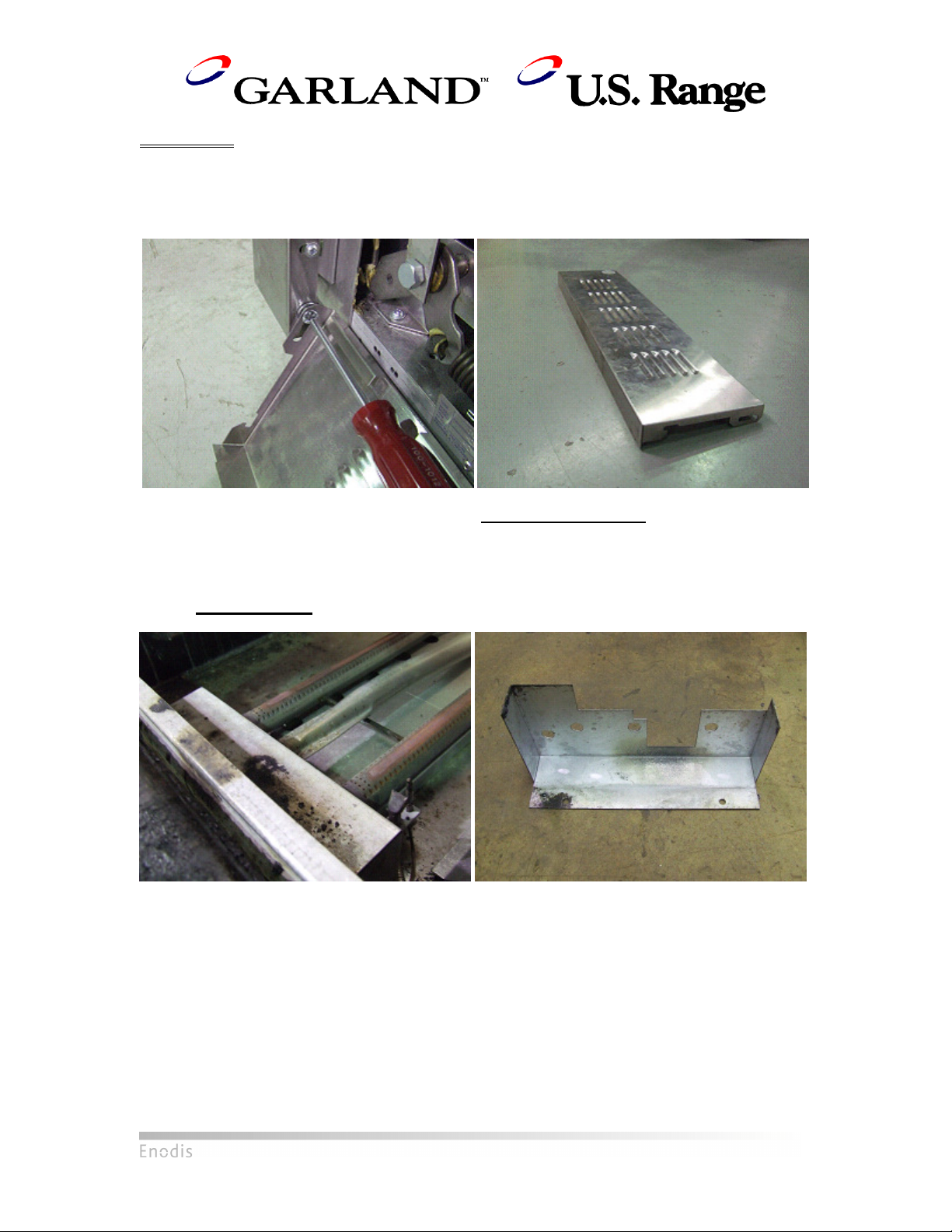
1) Remove Kick Plate
• Remove the two screws and washers at the hinge of the kick plate.
• This kick plate will not be reinstalled.
Left: Unscrewing hinge screw of kick plate
Right: Original kick plate. Will not be reinstalled.
2) Remove Front Air Shield
• The air shield is located directly above orifice. Remove by unscrewing two screws on the
top of the shield
• Do not dispose. Will be reinstalled later.
Left: Front Air Shield installed
Right: Front Air Shield uninstalled
07/19/07 P/N 4522555 Page 2
Page 3
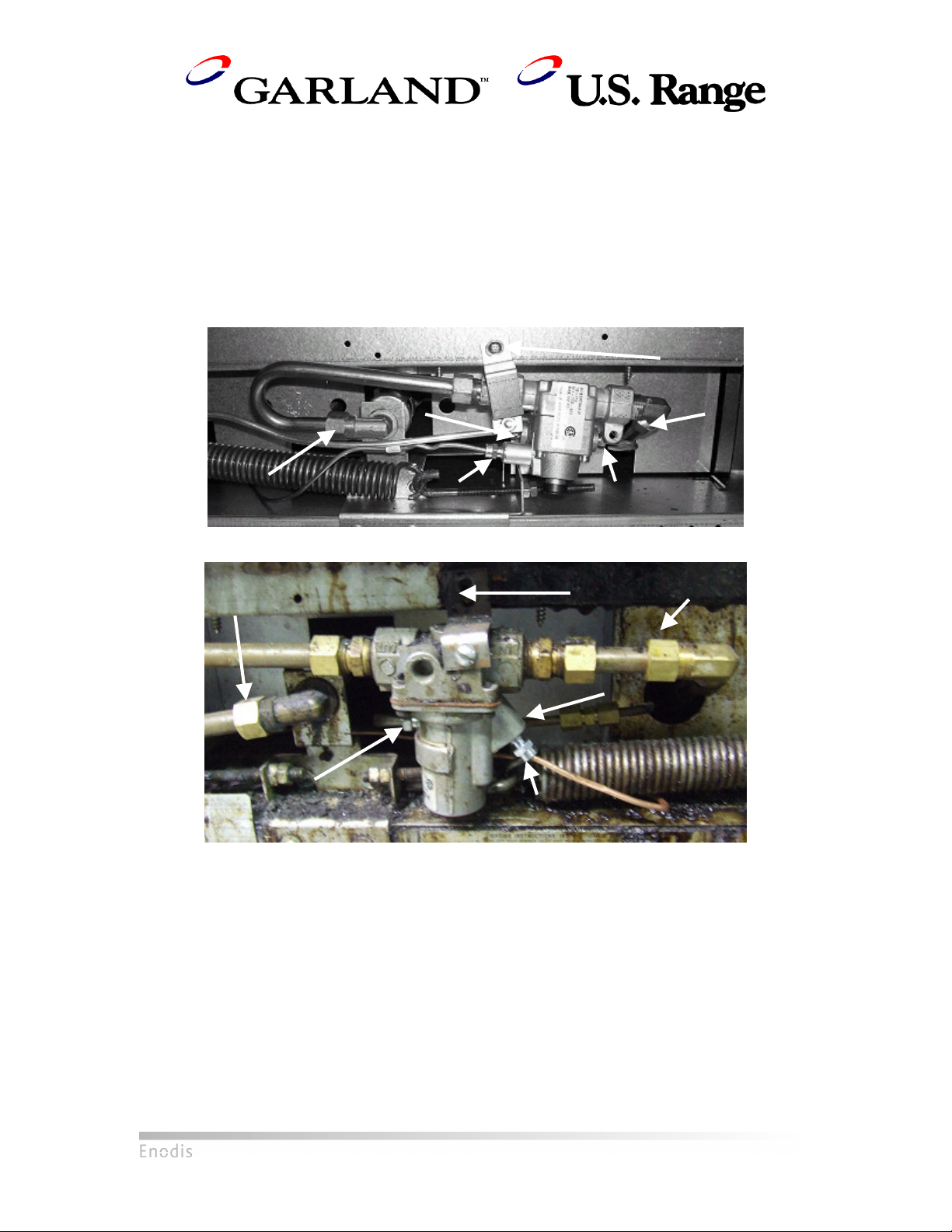
3) Uninstall Current Valve
• The following steps will apply if either an Invensys TS-11J Safety Valve or a Baso Valve
are installed originally. See the below pictures for reference.
1) Unscrew 11/16” compression nut on oven orifice fitting.
2) Unscrew 11/16” compression nut on 11/16” elbow on Main Burner Gas Inlet.
3) Unscrew 7/16” compression nut on Pilot Gas Inlet.
4) Unscrew 7/16” compression nut on Pilot Gas Outlet.
5) Unscrew 3/8” thermocouple nut.
6) Unscrew sheet metal screw holding bracket onto lower front frame.
7) Remove valve.
TS-11 Safety Valve: Prior to removal
Baso Safety Valve: Prior to removal
07/19/07 P/N 4522555 Page 3
Page 4

4) Remove Burner
• If the unit has an aeration plate, the burner is attached to aeration plate with one screw
near the back of the oven.
• If the unit does not have an aeration plate, the burner is attached the oven bottom with
one screw near the back of the oven
• Units with aeration plates and units without aeration plates will have different burners as
shown in the following pictures. Both will not be reinstalled. A replacement burner with
a welded side bracket is provided in the kit.
Left: Burner installed with aeration plate
Right: Burner uninstalled, aeration plate models. Flat bracket at end.
Left: Burner installed with no aeration plate
Right: Burner uninstalled, no aeration plate models. Tall bracket at end
07/19/07 P/N 4522555 Page 4
Page 5

5) Remove Aeration Plate (if present)
• If the pilot is installed on the left side of the burner in a horizontal position, unscrew the
bracket connecting the pilot bracket to the aeration plate.
• The plate is attached to the oven with two screws directly underneath the oven burner
orifice and another screw at the back end of the aeration plate.
Left: Removal of 2 screws underneath orifice
Right: Removed aeration plate with accompanying screws
6) Remove Original Pilot Assembly
• If pilot is installed on left side everything should now be detached and the entire
assembly can simply be pulled out
• If pilot is installed on the right side, unscrew the pilot bracket from the oven bottom and
remove the assembly.
07/19/07 P/N 4522555 Page 5
Page 6
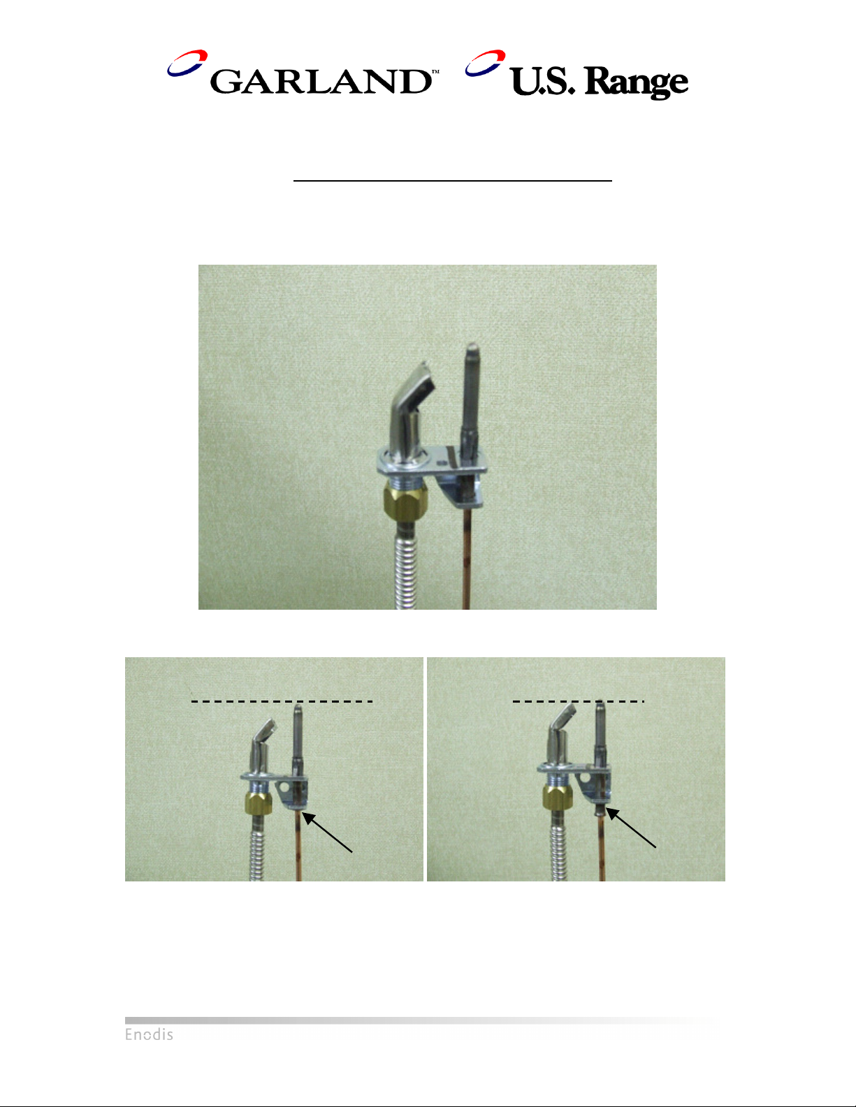
7) Assemble New Pilot Assembly
• A colored line on the top of the pilot indicates the type of fuel used. A BLACK line is used
on a natural gas pilot, whereas a RED line is used on a propane pilot. Both pilots are
included in this kit. Ensure that the correct pilot is used for the unit.
• Unscrew the nut on the end of the selected pilot to release the nut, the ferrule and the
orifice. Install the nut and the ferrule on one end of the flex tube.
• Place the orifice back into the pilot and screw on the flex tube.
• Push the thermocouple all the way into its slot on the pilot.
Finished Pilot Assembly
Left: Correctly assembled pilot with thermocouple pushed all the way through; thermocouple taller
than hood, no excess length sticking out from bottom
Right: Incorrect assembly, pilot not pushed all the way through; thermocouple shorter or equal in
height to hood, excess length sticking out from bottom
07/19/07 P/N 4522555 Page 6
Page 7

8) Attach Pilot Assembly to Welded Bracket on Burner
• Screw the pilot assembly to the welded bracket on the burner (Part 15, Assembly
Drawing) using the included self-tapping screw (Part 16, Assembly Drawing).
• Bend the flex tube and thermocouple approximately as shown below.
The pilot assembly fits onto the welded bracket via two holes, similar to original pilot bracket
9) Install Burner and Pilot Assembly
• Insert burner into orifice. Do not screw down the burner to the oven floor yet.
• Route thermocouple through the main gas / pilot gas tube opening in air shield.
• Route the pilot gas flex tube through the front area.
• Screw burner down to the hole at the far end of the oven (Part 9, Assembly Drawing).
Routing of pilot gas flex tube through front area, thermocouple through hole in shield.
07/19/07 P/N 4522555 Page 7
Page 8

10) Reinstall Front Air Shield, Hearth
• The shield should not clamp down on any of the tubing. The flex tubing can be bent out of
the way through the central opening in the shield.
New welded bracket burner installed.
11) Pull Out Flex Tube and Thermocouple
• Ensure that the thermocouple is routed through the hole in the front shield made for the
main gas inlet to the valve. This will make the thermocouple easier to install.
• Unbend and pull the pilot gas flex tube outwards as far as possible. Do not pull too hard
as the pilot bracket on the burner may be damaged.
Thermocouple and Pilot gas flex tube pulled out
07/19/07 P/N 4522555 Page 8
Page 9

Screw this nut
12) Install Extension Fitting (if applicable)
• If pilot gas tube going into the valve already has an extension piece (short piece of
tubing plus 3/16” brass fitting), unscrew the shorter piece of tubing and proceed to
Step 13. Otherwise, follow these steps to install the proper fitting.
• This step must be performed if a TS-11 valve was just removed.
• If a Baso valve was uninstalled, cut off 2.5” of the free end of the incoming pilot gas tube
to remove the original ferrule and nut and a section of the tubing. If a TS-11 valve was
uninstalled, cut off just enough tubing to remove the ferrule.
• Refer to the Assembly Drawing included in this manual:
i) Unscrew one end of the 3/16” fitting (Part 4, Assembly Drawing) to release the
nut and ferrule. Slide the nut and the ferrule onto the free end of the incoming
pilot gas tube.
ii) Insert the remaining portion of the fitting onto the end of the pilot gas tube. Screw
on the nut to firmly attach the fitting to the tube. See pictures below for details.
iii) Ensure all connections are leak-proof. Do not over-tighten.
Left: Measure 2.5” from tip of pilot tube and cut
Right: Pilot tube after cutting
onto the fitting
to secure the
fitting onto the
tube
3/16” Ferrule
Extension fitting installed, with nut released to show location of ferrule
07/19/07 P/N 4522555 Page 9
Page 10

13) Attach Main Burner Gas Line Flex Tubes onto Valve
• Two brass fittings (Part 7, Assembly Drawing) should already be installed on the Main
Burner gas inlet and outlet on the Baso valve.
• Unscrew the free end of each fitting to release the nut and ferrule. Install these on one
end of each 7/16” flex tube (Part 2, Assembly Drawing) and attach the tubes to the Main
Burner gas inlet and outlet on the Baso valve. See picture below for details.
Nut and ferrule unscrewed from fitting on valve, installed on one free end of each 7/16” flex tube
07/19/07 P/N 4522555 Page 10
Page 11

Main Burner gas
14) Screw on Pilot Gas Flex Tube, Adjust Main Burner Gas Fitting
• Remove the brass nut and ferrule originally on the pilot gas outlet on the Baso valve
(Part 5 and Part 6, Assembly Drawing). Install them onto the free end of the flex tube.
• Screw the pilot gas flex tube onto the Baso valve pilot gas outlet. This step should be
done first to minimize stress on the flex tube during later steps.
• The fitting on the Main Burner Gas Inlet needs to be turned 180° from its original position,
with the opening facing the right side of the oven. Loosen the nut, twist the fitting, and
ensure that the nut is tightened properly once it is facing the right direction.
fitting turned 180°°°°,
facing right side of
oven
Pilot Gas Flex Tube attached; Gas fitting turned around
07/19/07 P/N 4522555 Page 11
Page 12

15) Install New Pilot Gas Tube
• If a new 3/16” fitting (Part 4, Assembly Drawing) was installed on the pilot gas tube (Part
3, Assembly Drawing), unscrew the nut on the free end of the fitting to release the nut
and the ferrule. If a fitting was already installed on the pilot gas tube, unscrew one end of
the unused 3/16” fitting to release the nut and ferrule
• Unscrew the nut on the Baso valve pilot gas inlet to release the brass nut and the ferrule.
• Install these nuts and ferrules onto the new pilot gas tube as shown in the picture below.
3/16” Fitting Ferrule
3/16” Fitting Nut
Baso Valve Ferrule
Baso Valve Nut
New Pilot Gas Tube Assembly: Nuts and Ferrules
• Install the pilot gas tube as shown below. Connect to the valve first for easier installation.
New Pilot Gas Tube Installed
07/19/07 P/N 4522555 Page 12
Page 13

16) Connect Remaining Tubes and Thermocouple
• The free end of each 7/16” flex tube from the valve should be fitted with a 7/16” nut (Part
10, Assembly Drawing) and 7/16” ferrule (Part 11, Assembly Drawing).
• Connect the 7/16” flex tube and the thermocouple. Tighten all connections.
• The final tube connections should be comparable to the picture below.
Final Tube Configuration
17) Attach Lighting Instructions to Valve Bracket
The pilot lighting instructions are riveted on through the two holes in the bracket.
Ensure that the instructions are mounted in the correct direction shown below.
07/19/07 P/N 4522555 Page 13
Page 14

18) Attach Bracket to Oven
• Unscrew the two screws holding the orifice bracket to the lower oven frame.
• Slip the bracket (Part 8, Assembly Drawing) underneath the valve assembly such that the
taller face is flush up against the lower oven frame.
• Position the screw holes on the bracket such that two of them line up with the holes used
for the orifice bracket. The third hole on the far right of the bracket will line up with a hole
on the lower oven frame.
• Screw bracket onto oven frame with sheet metal screws (Part 9, Assembly Drawing).
Left: Unscrewing two lower screws of orifice bracket
Right: Attached valve bracket with arrows indicating location of screws
07/19/07 P/N 4522555 Page 14
Page 15

19) Attach Valve Onto Bracket
• The valve is attached to the bracket using the bolt and nut provided (Part 13 and Part 12,
Assembly Drawing). Insert the bolt into the hole through the valve and align it with the
small hole on the back of the bracket. The large hole on the front may be used to insert
the bolt into position.
• Screw the nut onto the protruding end of the bolt behind the bracket.
Attaching bolt inserted through hole in valve indicated by arrow
Nut holding bold in place on back of bracket
07/19/07 P/N 4522555 Page 15
Page 16

20) Install New Kick Plate
• The new kick plate (Part 14, Assembly Drawing) slants outwards to accommodate the
valve. Ensure that the correct kick panel is installed.
Left: Old kick plate with flat profile. Do not install this kick plate.
Right: New kick plate with slanted profile.
• The new kick plate is designed to hook onto existing screws on the oven frame. Look for
the original hooking screws used for the original kick plate.
Original hooking screw on oven frame. Look for a similar screw on the other side of the oven
• Hook the kick plate onto the screws using the L-shaped indentations on the sides of the
kick plates. Ensure that the plate does not rest against the bracket directly.
07/19/07 P/N 4522555 Page 16
Page 17

Installation Complete
Installation Complete – Kick Plate Off
Installation Complete – Kick Plate On
07/19/07 P/N 4522555 Page 17
 Loading...