

Garland GIU2.5 BI, GIU5.0 BI, GIU3.5 BI, GIU3.5DUAL BI, GIWOK3.5 BI Installation And Operation Manual
...
INSTALLATION AND
S
A
N
I
T
A
T
I
O
N
L
I
S
D
CM
OPERATION MANUAL
GARLAND INDUCTION SINGLE, DUAL AND WOK BUILT IN
UNITS, MODELS: GIU2.5 BI, GIU3.5 BI, GIU5.0 BI, GIU3.5
DUAL BI, GIU5.0 DUAL BI, GIWOK3.5 BI & GIWOK5.0 BI
86037
C
PLEASE READ ALL SECTIONS OF THIS MANUAL
FOR YOUR SAFETY:
DO NOT STORE OR USE GASOLINE
OR OTHER FLAMMABLE VAPORS OR
LIQUIDS IN THE VICINITY OF
THIS OR ANY OTHER
APPLIANCE
WARNING:
IMPROPER INSTALLATION, ADJUSTMENT,
ALTERATION, SERVICE OR MAINTENANCE
CAN CAUSE PROPERTY DAMAGE, INJURY,
OR DEATH. READ THE INSTALLATION,
OPERATING AND MAINTENANCE
INSTRUCTIONS THOROUGHLY
BEFORE INSTALLING OR
SERVICING THIS EQUIPMENT
Users are cautioned that maintenance and repairs must be performed by a Garland authorized service agent
using genuine Garland replacement parts. Garland will have no obligation with respect to any product that has been
improperly installed, adjusted, operated or not maintained in accordance with national and local codes or installation
instructions provided with the product, or any product that has its serial number defaced, obliterated or removed,
or which has been modified or repaired using unauthorized parts or by unauthorized service agents.
For a list of authorized service agents, please refer to the Garland web site at http://www.garland-group.com.
The information contained herein, (including design and parts specifications), may be superseded and is subject
to change without notice.
AND RETAIN FOR FUTURE REFERENCE.
THIS PRODUCT HAS BEEN CERTIFIED AS
COMMERCIAL COOKING EQUIPMENT AND
MUST BE INSTALLED BY PROFESSIONAL
PERSONNEL AS SPECIFIED.
INSTALLATION AND ELECTRICAL CONNECTION
MUST COMPLY WITH CURRENT CODES:
IN CANADA - THE CANADIAN ELECTRICAL
CODE PART 1 AND / OR LOCAL CODES.
IN USA – THE NATIONAL ELECTRICAL CODE
ANSI / NFPA – CURRENT EDITION.
CONFORMS TO UL-197 & NSF-4 CERTIFIED TO
CAN/CSA C22.2NO. 109 VDE EN60335-2-38.
GARLAND COMMERCIAL INDUSTRIES
185 East South Street
Freeland, Pennsylvania 18224
Phone: (570) 636-1000
Fax: (570) 636-3903
Part # 4520895 (01/31/08) © 2004 Garland Commercial Industries, Inc.
Part # 4529895 (01/31/08) Page 1
GARLAND COMMERCIAL RANGES, LTD.
1177 Kamato Road, Mississauga, Ontario L4W 1X4
CANADA
Phone: 905-624-0260
Fax: 905-624-5669
Enodis UK LTD.
Swalloweld Way, Hayes, Middlesex UB3 1DQ ENGLAND
Telephone: 081-561-0433
Fax: 081-848-0041

Part # 4520895 (01/31/08)Page 2

Part # 4529895 (01/31/08) Page 3
TABLE OF CONTENTS
DIMENSIONS AND SPECIFICATIONS,
GIU 2.5 BI..............................4
DIMENSIONS AND SPECIFICATIONS,
GIU 3.5/5.0 BI ..........................5
DIMENSIONS AND SPECIFICATIONS,
GIU 3.5/5.0 BI DUAL ....................6
DIMENSIONS AND SPECIFICATIONS,
GI 3.5/5.0 BI WOK ......................7
Operation And Control .......................8
Operation Conditions ........................8
Plug Descriptions ............................8
INTRODUCTION........................8
Application ..................................8
Purpose of induction cookers. . . . . . . . . . . . . . . . . 8
Description of products ......................8
INSTALLATION.........................9
Requirements of Installation ..................9
Installation Ambience ........................9
Electrical Connections .......................9
Cut Out .....................................10
Fresh Air Intake Installation .................10
Unit Installation .............................10
Remote Control Installation .................11
For Units Used Up To October 2001 ...... 11
For Units Used From October 2001.......12
OPERATION...........................13
Function Test ...............................13
Heating ....................................13
Control Knob ...............................13
Simmer Control .............................13
SAFETY CONCERNS ...................14
Description Of Danger Signs ................14
Safety Conscious Work ......................14
Cooking Process ............................14
Comfort ....................................14
Pan Detection ..............................14
Control Of The Heating Area. . . . . . . . . . . . . . . . . 14
Out Of Operation ...........................14
Operator/Operating Personnel Safety
Information .................................15
Unauthorized Reconstruction And
Use Of Spare Parts ..........................15
TROUBLE SHOOTING..................16
Error Messages .............................16
Trouble Shooting Guide .....................16
CLEANING AND SERVICING ............18
Cleaning ....................................18
Support ....................................18
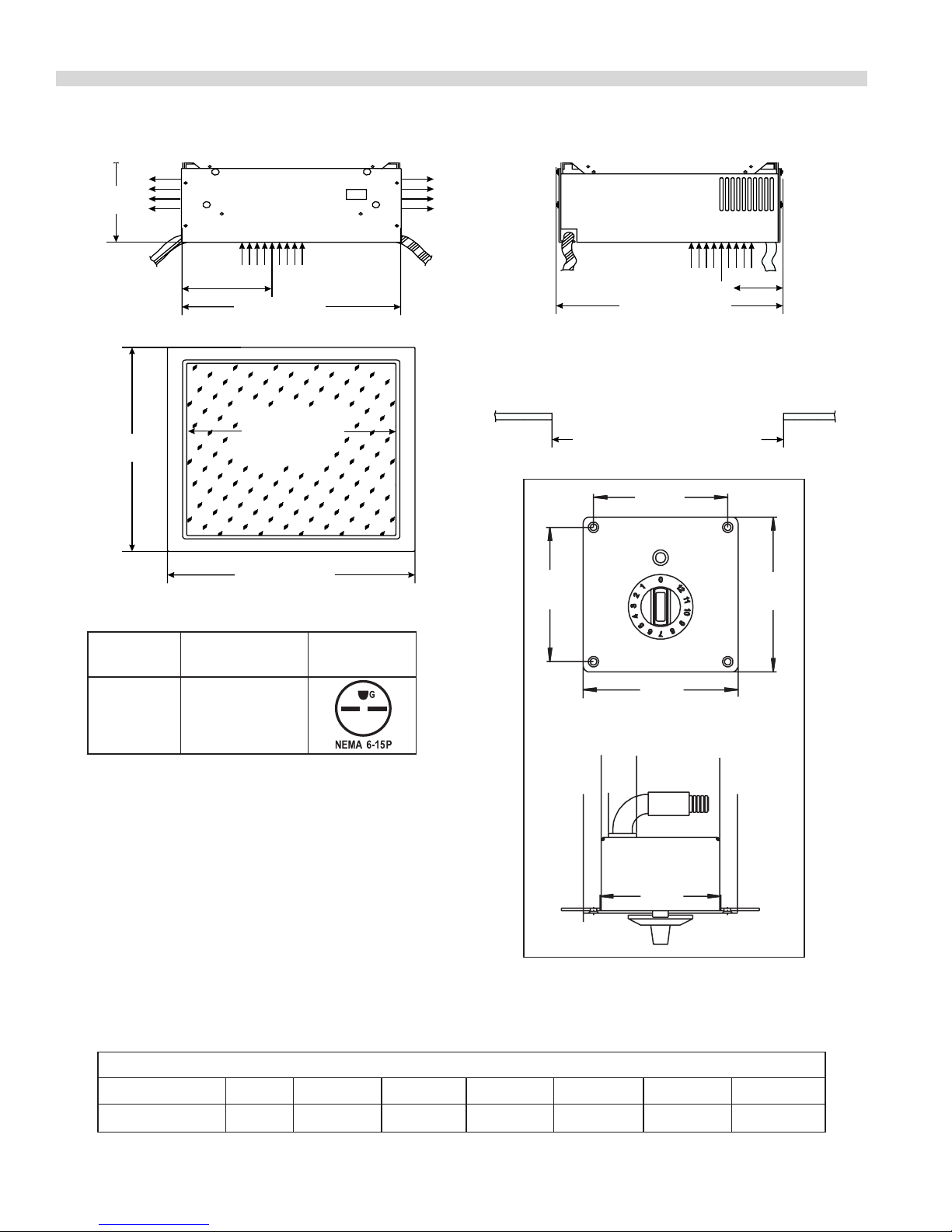
11 1/4" (285mm)
3"(76mm)
Exhaust
103/8"(260mm)
CeranGlass
DIMENSIONS AND SPECIFICATIONS, GIU 2.5 BI
4.09"
[104mm]
4.09"
[104mm]
4.72"
[120mm]
4.72"
[120mm]
0"
0.55"
[14mm]
0.75"
[19mm]
1.73"
[44mm]
4.17"
[106mm]
4.72"
[120mm]
3.66"
[93mm]
REMOTE
5 1/8"
(130mm)
Cable
6' Corded Plug
(208/240 Volt,
60 Cycle Units Only)
Fresh Air
4 3/8" (111mm)
10 7/8" (275mm)
For
Controls
Required Cut-Out Of Work Top
12 1/4"
(310mm)
MODEL
GIU-2.5 BI
12 1/4" (310mm)
Plug Congurations:
Electrical
Chararactericts
208V/60Hz/1Ø
240V/60 Hz/1Ø
11 1/2" (292mm) x 11 1/2" (292mm)
Plug
Model Watts 208/60/1 208/60/3 240/60/1 230/50/1 400/50/3 440/60/3
GUI-2.5 BI 2500 12 amp N/A 9 amp 10 amp N/A N/A
Note: Above remote control used from October 2001, for
remote switch used up to October 2001 see “Remote Control
Installation”.
Electrical Loading:
Part # 4520895 (01/31/08)Page 4

Part # 4529895 (01/31/08) Page 5
DIMENSIONS AND SPECIFICATIONS, GIU 3.5/5.0 BI
6 1/8"
(155mm)
Exhaust
6' Cord & Plug
(208/240 Volt
60 Cycle Units Only)
15 1/8"
(384mm)
Plug Congurations:
MODEL
GIU-3.5 BI
6"
(153mm)
13 1/8" (333mm)
12 5/8" (320mm)
(384mm)
Electrical
Chararactericts
208V/60Hz/1Ø
240V/60 Hz/1Ø
Fresh Air
CeranGlass
15 1/8"
Plug
Cable
For
Controls
4.09"
[104mm]
6 3/8"
(163mm)
13 1/2" (343mm)
The Required Cut-Out Of The Work Top:
14" (356mm) x 14" (356mm)
4.09"
[104mm]
4.72"
[120mm]
4.72"
[120mm]
0.55"
0"
1.73"
[14mm]
0.75"
[19mm]
[44mm]
4.17"
[106mm]
4.72"
[120mm]
GIU-5.0 BI 208V/60HZ/3Ø
Model Watts 208/60/1 208/60/3 240/60/1 230/50/1 400/50/3 440/60/3
GUI-3.5 BI 3500 16 amp N/A 14 amp 15 amp N/A N/A
GUI-5.0 BI 5000 N/A 14 amp N/A N/A 8 amp 7 amp
Note: Above remote control used from October 2001, for
remote switch used upto October 2001 see “Remote Control
Installation”.
Electrical Loading:
REMOTE
3.66"
[93mm]
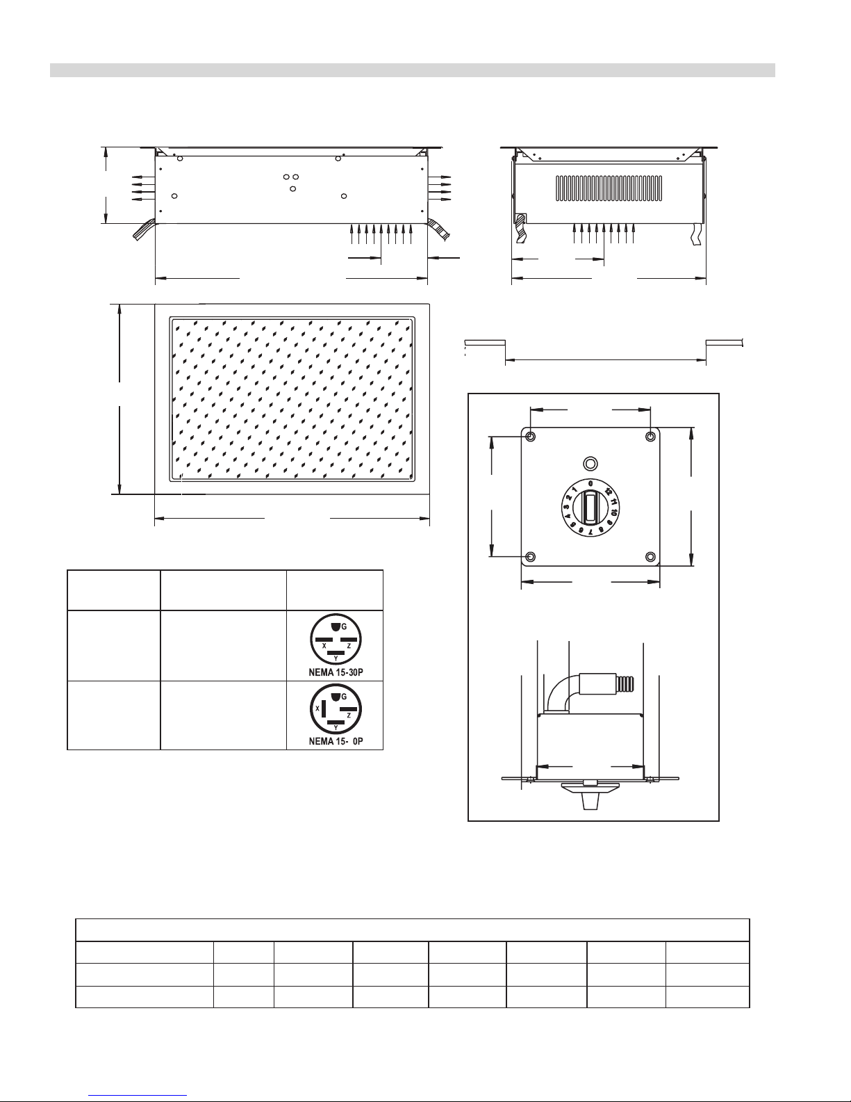
DIMENSIONS AND SPECIFICATIONS, GIU 3.5/5.0 BI DUAL
4.09"
[104mm]
4.09"
[104mm]
4.72"
[120mm]
4.72"
[120mm]
0"
0.55"
[14mm]
0.75"
[19mm]
1.73"
[44mm]
4.17"
[106mm]
4.72"
[120mm]
3.66"
[93mm]
REMOTE
5-3/8"
(137mm)
6-Foot Cord
& Plug
(208/240Volt,
60 Cycle
Units Only)
15"
(380mm)
23-3/8" (594mm)
(645mm)
Plug Congurations:
25-3/8"
Intake
3-3/8"
(86mm)
Exhaust
Control
Cable
6-3/8"
(163mm)
Intake
13-1/2"
(343mm)
The Required Cut-Out Of The Work Top:
14" (356mm) x 24" (610mm)
MODEL
GIU-3.5 Dual
BI
GIU-5.0 Dual
BI
Electrical
Chararactericts
208V/60Hz/3Ø
208V/60HZ/3Ø
Plug
5
Note: Above remote control used from October 2001, for
remote switch used up to October 2001 see “Remote Control
Installation”.
Electrical Loading:
Model Watts 208/60/1 208/60/3 240/60/1 230/50/1 400/50/3 440/60/3
GIU-3.5 DUAL BI 7000 N/A 20 amp N/A N/A 10 amp 9 amp
GIU-5.0 DUAL BI 10,000 N/A 28 amp N/A N/A 15 amp 13 amp
Part # 4520895 (01/31/08)Page 6

Part # 4529895 (01/31/08) Page 7
DIMENSIONS AND SPECIFICATIONS, GI 3.5/5.0 BI WOK
4.09"
[104mm]
4.09"
[104mm]
4.72"
[120mm]
4.72"
[120mm]
0"
0.55"
[14mm]
0.75"
[19mm]
1.73"
[44mm]
4.17"
[106mm]
4.72"
[120mm]
3.66"
[93mm]
REMOTE
83/8"
(213mm)
6’ CordandPlug
(208/240Volt
60CycleUnitsOnly)
151/8"
(384mm)
6"
(152mm)
FRESHAIR
131/8"
(333mm)
117/8"
(300mm)
151/8"
(384mm)
1/16"
EXHAUST
Cable
for
Controls
141/4"
(361mm)
63/8"
(163mm)
14 1/2" (368mm) x 14 1/2" (368mm)
135/8"
(344mm)
Required Cut-Out of WorkTop
Plug Congurations:
Model
Electrical
Characteristics
Plug
GIWOK-3.5BI208V/60Hz/1Ø
240V/60Hz/1Ø
GIWOK-5.5
BI
208V/60Hz/1Ø
Note: Above remote control used from October 2001, for
remote switch used up to October 2001 see “Remote Control
Installation”.
Electrical Loading:
Model Watts 208/60/1 208/60/3 240/60/1 230/50/1 400/50/3 440/60/3
GIWOK-3.5 BI 3500 16 amp N/A 14 amp 15 amp N/A N/A
GIWOK-5.0 BI 5000 N/A 14 amp N/A N/A 8 amp 7 amp
DIMENSIONS AND SPECIFICATIONS, Continued
Operation And Control
Lamp operation 24V DC/max. 40mA (Green)
Output regulator - Potentiometer 10k Ohm
Operation Conditions
Max. Tolerance Of The Nominal
Supply Voltage
Supply Frequency 50/60 Hz
Protection Class 1P 43
Minimal Diameter Of The Pan 5” (127mm)
+6/-10%
INTRODUCTION
Application
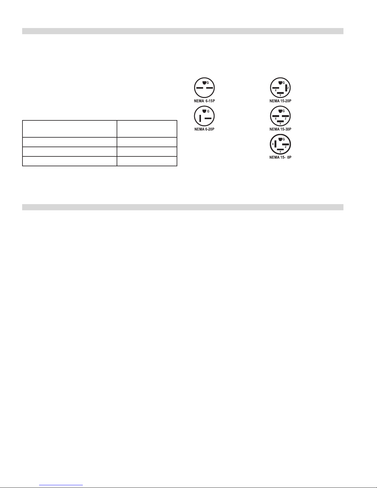
Plug Descriptions
208/240 volt,
single phase, 15
amp
208/240 volt,
single phase, 20
amp
Description of products
208 volt,
3 phase,
20 amp
208 volt,
3 phase,
30 amp
208 volt,
3 phase,
50 amp.
5
The following instructions contain information, which
is fundamentally important and must be taken into
account during assembly, operation and maintenance.
They must therefore read very carefully before installation
and operation by the responsible specialist sta and the
operator(s). They must always be available for consultation at
the place of operation.
Purpose of induction cookers
The Garland induction unit cookers are especially suitable
as cookers in the kitchen and for the preparation of meals
on the table. A cooker can be used for cooking, warming up,
keeping warm, ambéing, roasting, etc. The cookers are to
be used only with pans made of material which is suitable for
induction. There are specic manufacturers who sell special
types of pots and pans for induction cooking.
NOTE: For Wok models, only use supplied pans or “Spring of
Switzerland” wok pans. Other pans may not have the same
shape as the ceramic wok bowl, causing overheating and
cracking of the ceramic.
DO NOT use induction cookers to heat up any other
metallic objects other than pots and pans provided for it.
We manufacture several basic types of induction cookers
with various performances and measurements. All are
built to last; they are also compact and powerful with a
revolutionary technology in a complete case of stainless
steel. All of our accessories are designed to coordinate with
the induction units and since each unit is equipped with
continuous control, they allow ecient cooking.
Features include:
• Simple operation with rotary switch
• Compact powerful electronics enable at construction and
safe operation
• A maximum of safety thanks to multiple safety functions
• Short cooking time
• Electronic checking
• Compact measurement – light weight
• Meets all current standards: VDE EN 60335-1/-2/36, CEconforming
• UL197; CAN/CSA/C22.2 No., 109, NSF 4-1996
Part # 4520895 (01/31/08)Page 8
Part # 4529895 (01/31/08) Page 9
INSTALLATION
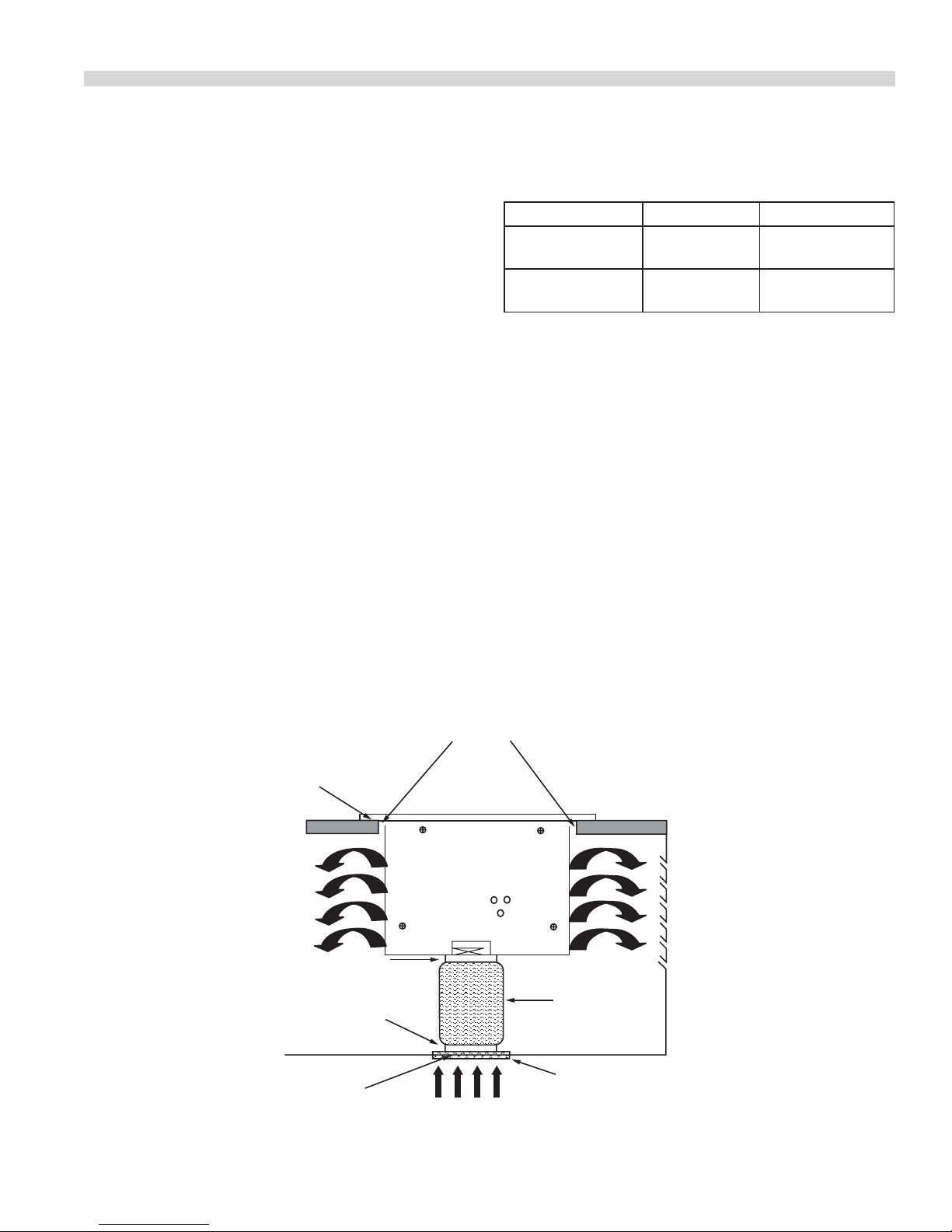
Requirements of Installation
The underside and sides of the induction unit must be
absolutely clear of obstructions to provide for adequate
cooling air to enter and exhaust. Cooling air enters from the
bottom of the unit and is discharged either from the sides
(single or wok units) or from the rear (double units). An
air intake kit is provided to ensure adequate cooling air is
brought to the unit. A minimum of 30 sq inch opening must
be provided for the heated air to be discharged into the
room.
1 Make Sure that the induction unit does not take in hot
ambient air (concerns units standing side by side, or one
behind the other, or standing near a frying pan or oven).
2. The induction unit must not be placed near or on a hot
surface.
3. Make sure that the induction unit does not take in grease
laden air which is produced by other applications (deep
fat fryer, grill, frying pan). In which case you must use an
air an air duct (available as an accessory).
4. The air intake temperature must be under 104°F (40°).
5. The operating sta has to make sure that the installation,
support and inspection is done by qualied personnel.
Installation Ambience
CONDITIONS STORAGE FUNCTION
Max. Ambient
Temperature
Max. Relative
Humidity Of Air
> -4°F (-20ºC) to
158°F (70ºC)
> -10% to 90% > 30% to 90%
> 41ºF (5ºC) to
104ºF (40ºC)
Electrical Connections
Turn the control knob to the OFF-position before connecting
the cooker to the voltage supply.
The operator has to insure that all installation, maintenance
and inspection work is carried out by authorized and
qualied personnel.
1. Check and ensure that the supply voltage matches the
voltage given on the specication plate.
2. The electrical connections must satisfy local house
installation regulations. The valid national and local
regulations must be observed.
3. The cooker is provided with a cord and plug (60 cycle
units only).
Cut Out Opening
Silicone
Louvered
Air Exhaust
Opening
(By Installer)
Sleeve with hose clip:
mounted on bottom of unit
Sleeve with hose clip:
mounted to cabinet
Air Intake Housing
See Fig. # 1
Fresh Air Supply
Aluminum air duct
(Max 96" (8'))
mounted on collars
with hose clamps
Removable grease lter and air
intake housing mounted on
cabinet

INSTALLATION Continued
Cut Out
The size of the cut out required will vary depending on
the model of the unit. (See cut-out dimensions for the
various unit in the dimensions and specications sections).
Make sure there is enough depth below the top surface
to accommodate the depth of the unit and the air intake
connection. Apply silicone to the top of the table and press
the unit frame onto the silicone, allowing for a complete
watertight seal between the unit and the table.
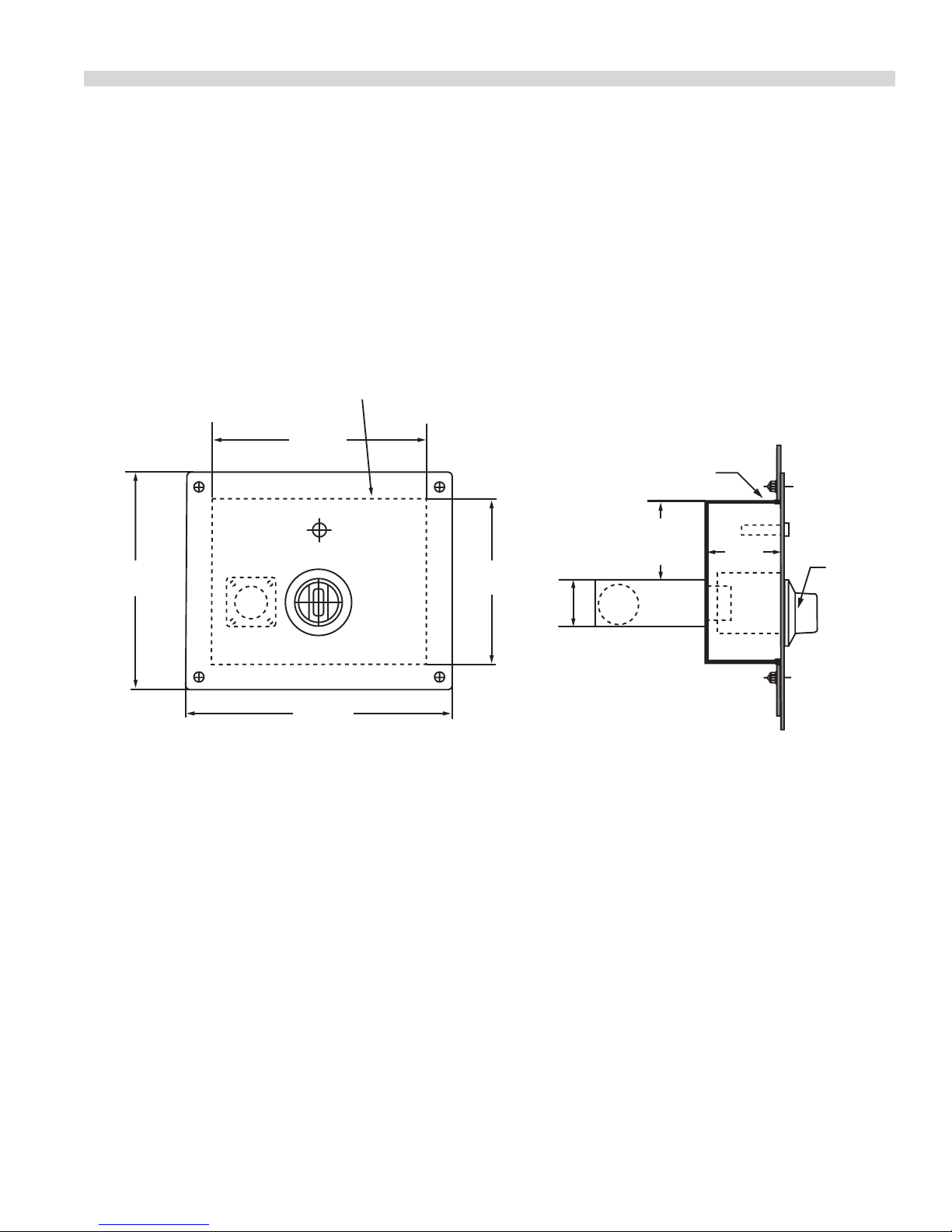
Fresh Air Intake Installation
The built-in induction units require a cooling air intake to
operate eectively. The air intake housing is mounted to
the cabinet, and is tted with a removable stainless steel
grease lter that can be cleaned in a dishwasher. Install the
air intake housing and connect it to the induction unit with
the aluminum air duct. Maximum length of this air inlet is
to be 96” (8’). Make sure the cabinet is also equipped with
a louvered air exhaust having a size of no less than 30 sq
inches (50 sq inches for dual units) for the hot air to escape
(by installer). Failure to provide adequate ventilation for the
unit will result in the unit overheating, nuisance shut down
and potential failure of the unit.
Figure 1.
Figure 1 Continued
4 HOLES
CUTOUT
9.125" x 7"
[231.8mm x 177.8mm]
Unit Installation
Check and ensure, that the supply voltage matches the
voltage given on the specication plate.
The cooker must be installed so that it is level and that the
top of the unit has been sealed to the counter. Install the air
intake kit to the bottom of the unit, and ensure that there is a
minimum of 30 sq inch opening to allow the heated air from
the cooling fan to be discharged into the room.
TOP VIEW
11" [279.4mm]
10 3/16" [258.8mm]
8 3/16"
[208 mm]
9"
[288.6 mm]
FRONT VIEW
5/32"
[4mm]
4 Holes
Part # 4520895 (01/31/08)Page 10
Part # 4529895 (01/31/08) Page 11
INSTALLATION Continued
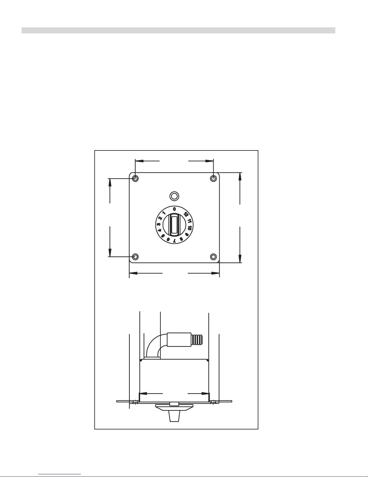
Remote Control Installation
Install the remote mounted controls at the front of the unit in
a convenient location, and connect to the unit (2 controls are
provided for the dual hob model).
Figure 2
Cut-Out For
Control Box
6 1/2"
[165 mm]
6 3/8"
[162mm]
[127mm]
For Units Used Up To October
Up to serial # IN16.0044.101 (See Fig 2).
Edge
Protection
5"
1 3/8"
[35mm]
Cable
2 3/8"
[60 mm]
2 1/4"
[57mm]
Control
Knob
7 7/8"
[200mm]
4.09"
[104mm]
4.09"
[104mm]
4.72"
[120mm]
4.72"
[120mm]
0"
0.55"
[14mm]
0.75"
[19mm]
1.73"
[44mm]
4.17"
[106mm]
4.72"
[120mm]
3.66"
[93mm]
REMOTE
INSTALLATION Continued
For Units Used From October
From serial # IN16.0045.1001
The remote rotary control is mounted on a plate measuring
4.72” (120mm) high x 4.72” (120mm) wide that is mounted to
the front of a fabricated cabinet (supplied by others) with 4
screws. The Cut-out opening for the control is 3.40” (86mm)
high x 3.40” (86mm) wide.
Part # 4520895 (01/31/08)Page 12
 Loading...