

Garland GI-MO/DU 7000, GI-MO/DU 14000, GI-MO/DU 10000, GI-MO/QU 14000, GI-MO/QU 20000 Installation, Operation And Maintenance Manual
...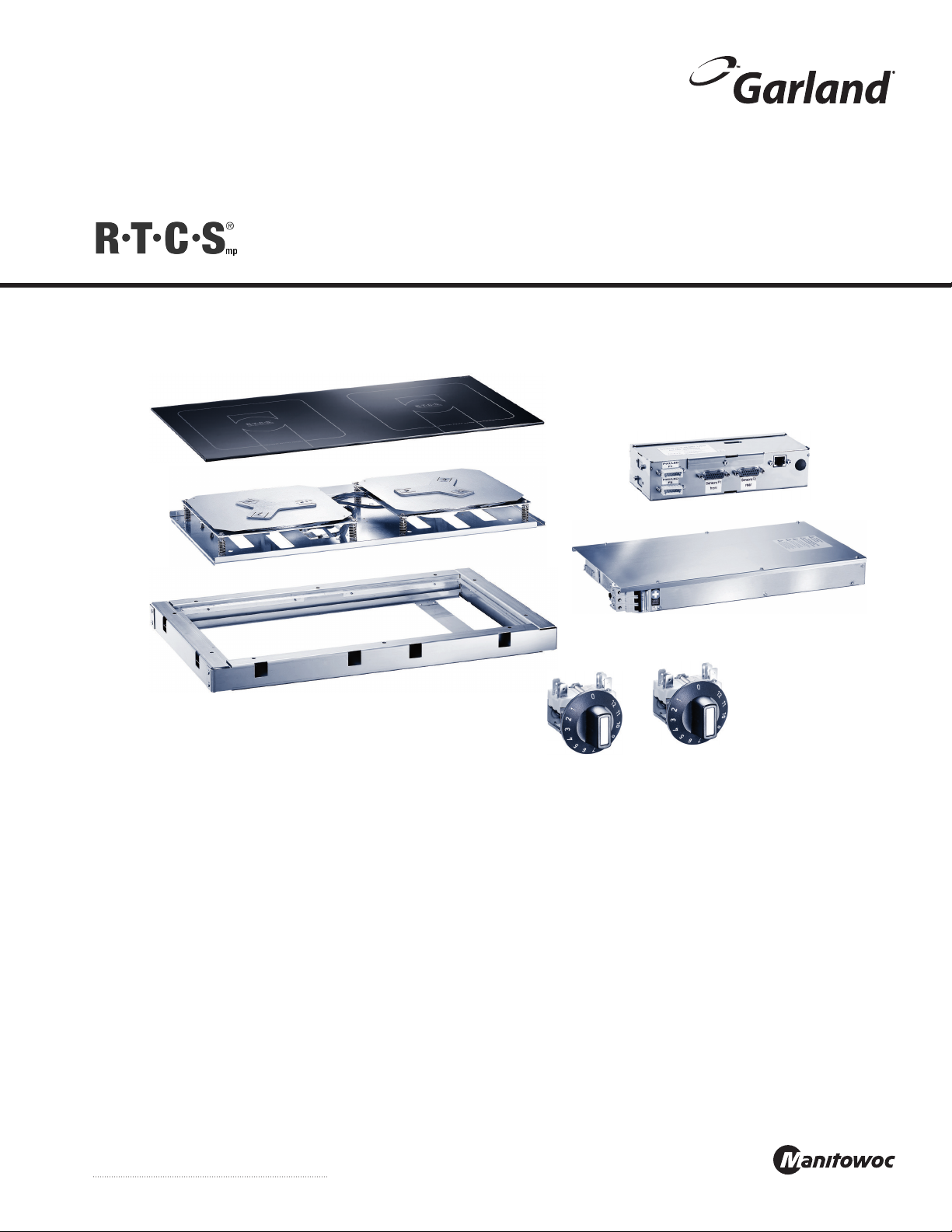
Induction Designer Series
Module-Line Built-In Models
Installation, Operation and Maintenance Manual
models
GI-MO/DU 7000
GI-MO/DU 10000
GI-MO/DU 14000
GI-MO/QU 14000
GI-MO/QU 20000
GI-MO/QU 21000
GI-MO/QU 24000
GI-MO/QU 28000
Original Instructions
Part Number 4532415 Rev 5 12/15

READ THIS MANUAL
Warning
n
Read this manual thoroughly before installing,
operating, or performing maintenance on the
equipment. Failure to follow instructions in this manual
can cause property damage, injury or death.
This manual must always be available for reference at
the place of operation.
This manual is intended for kitchen consultants, cabinet
designers, fabricators, installers, owners and operators of
our appliances.
Owners, consultants, fabricators and designers:
In order for the induction appliance to function safely
and normally, you must read and understand all
specific and critical requirements when designing the
location and the counter for the appliance.
Installers, operators and staff:
For your safety and safety of the others, you must
observe all safety instructions during installation,
operation and maintenance of the equipment.
Should you require technical assistance, call your factory
authorized service agent or distributor. Always have your
model and serial number available when you call.
Your Factory Authorized Service Agent
ABOUT THIS MANUAL
Throughout this manual, the induction appliance model
indicated on the cover page is referred to as appliance,
induction appliance or equipment.
A period (.) is used in this manual as the decimal separator.
Original measurements are in metrics. Measurements in
imperial are provided for reference.
Not ALL models, options and accessories are available in all
geographical regions. Please consult your local equipment
supplier for the availability of the specific products in your
region.
INSPECT THE SHIPMENT
Thoroughly inspect the equipment upon delivery.
Immediately report to the delivery carrier, any damage that
occurred during transportation and request for a written
inspection report from a claim inspector.
Your shipment might include small packages of fasteners
or silicone strips for installation. Keep all packages.
KEEP THE PACKING SLIP
The packing slip attached to the shipment contains
detailed information on all components. Keep the packing
slip for reference.
Service Agent Telephone Number
Your Local Equipment Supplier
Supplier Telephone Number
Model Number
Serial Number
Date of Installation

Safety Notices
Safety Notices
DEFINITIONS
DANGER
Indicates a hazardous situation that, if not avoided, will
result in death or serious injury. This applies to the most
extreme situations.
Warning
n
Indicates a hazardous situation that, if not avoided,
could result in death or serious injury.
Caution
,
Indicates a hazardous situation that, if not avoided,
could result in minor or moderate injury.
Notice
Indicates information considered important, and is used
to address practices not related to physical injury. For
example, messages relating to property damage.
NOTE: Indicates useful, extra information about the
procedure you are performing.
Reference: ANZI Z535.6-2011
SAFETY SYMBOLS AND WARNINGS ON THE APPLIANCE
This symbol alerts you to a hazardous situation
that WILL or COULD cause serious bodily harm
or death. Be alert and implement relevant safety
precautions.
DANGER - HIGH VOLTAGE
This dangerous voltage warning symbol
indicates a risk of electric shock and hazards
from dangerous voltage.
Electromagnetic Field
Warning
RISK OF FIRE OR ELECTRIC SHOCK! DO NOT OPEN!
To reduce the risk of fire or electric shock, do not remove or
open cover. No user serviceable parts inside.
Refer servicing to qualified personnel.
CAUTION ATTENTION
DISCONNECT FROM SUPPLY CIRCUIT BEFORE OPENING
DISCLAIMERS
DANGER
Disregarding any safety instructions may cause harm to
people, the surroundings, and the equipment. Garland
is not responsible for any damages or personal injury
caused by failure to observe any safety requirements.
Risks involved when disregarding safety precautions
include, but not limiting to:
• Death or injury caused by electric shock.
• Burn injury caused by contacting overheated cooking
surface, cookware, or oil and grease.
• Damage to the equipment caused by using
unsuitable cookware.
DANGER
Do not install or operate equipment and/or accessories
that have been misused, abused, neglected, damaged,
or altered from that of original manufactured
specifications.
DANGER
Contact the manufacturer if you intend to make any
changes on the equipment. For safety reasons, always
use genuine parts and accessories approved by the
manufacturer or authorized representative. Refer to the
warranty documents for your equipment.
DANGER
Owners and operators are cautioned that maintenance
and repairs must be performed by an authorized service
agent using only genuine replacement parts. The
manufacturer will have no obligation with respect to any
product that has been improperly installed, adjusted,
operated or not maintained in accordance with national
and local codes and/or installation instructions provided
with the product or any product that has its serial
number defaced, obliterated or removed, and/or which
has been modified or repaired using unauthorized parts
or by unauthorized service agents.
DANGER
Improper installation, adjustment, alteration, service,
or maintenance of this appliance or installation of
a damaged appliance can result in DEATH, INJURY,
EQUIPMENT DAMAGE, and void the warranty.
DANGER
All utility connections and fixtures must be maintained
in accordance with local and national codes.
Part Number 4532415 Rev 5 12/15 3
Safety Notices
Warning
n
Do not store or use gasoline or other flammable vapors
or liquids in the vicinity of this or any other appliance.
Never use flammable oil soaked cloths or combustible
cleaning solutions for cleaning.
Warning
n
This appliance is not intended for use by persons
(including children) with reduced physical, sensory or
mental capabilities, or lack of experience and knowledge,
unless they have been given supervision concerning
use of the appliance by a person responsible for their
safety. Do not allow children to play with this appliance.
Warning
n
This product contains chemicals known to the State
of California to cause cancer and/or birth defects or
other reproductive harm. Operation, installation, and
servicing of this product could expose you to airborne
particles of glass-wool or ceramic fibers, crystalline
silica, and/or carbon monoxide. Inhalation of airborne
particles of glass-wool or ceramic fibers is known to the
State of California to cause cancer. Inhalation of carbon
monoxide is known to the State of California to cause
birth defects or other reproductive harm.
your area.
CORRECT DISPOSAL OF THIS PRODUCT
This marking shown on the product
indicates that the product should not be
disposed as household waste or regular
commercial waste. Instead it shall be
handed over to the applicable collection
point for the recycling of electrical and electronic
equipment. By ensuring this product is disposed correctly,
you will help prevent potential harm to the environment
or human health, which could otherwise be caused by
inappropriate waste handling of this product.
For more detailed information regarding recycling of the
product, please contact your local city office or your waste
disposal service.
DANGER
Induction appliances, sent for disposal, can be brought
back into operation and their use must be avoided.
NOTE: The appliance is built with common electrical,
electromechanical and electronic parts. No batteries are
used.
NOTE: The owner and operator are responsible for the
proper and safe disposal of the appliance.
Warning
n
Authorized Service Representatives are obligated to
follow industry standard safety procedures, including,
but not limited to, local/national regulations for
disconnection / lock out / tag out procedures for all
utilities including electric, gas, water and steam.
Notice
This appliance is not approved or authorized for home
or residential use, but is intended for commercial
applications only. The manufacturer and/or authorized
representative will not provide service, warranty,
maintenance or support of any kind other than in
commercial applications.
Notice
Routine adjustments and maintenance procedures
outlined in this manual are not covered by the warranty.
NOTE: Proper installation, care and maintenance are
essential for maximum performance and trouble-free
operation of your equipment. Visit our website
www.mtwkitchencare.com for manual updates,
translations, or contact information for service agents in
4 Part Number 4532415 Rev 5 12/15

Safety Notices
Table of Contents
Section 1
General Information
Section 2
Installation
Table of Contents
Definitions.................................................................................................................................................3
Safety symbols and Warnings on the Appliance ........................................................................3
Disclaimers ................................................................................................................................................3
Correct Disposal of This Product .......................................................................................................4
Description of Product .......................................................................................................7
Application .........................................................................................................................7
Compliances .......................................................................................................................7
Components and Features ................................................................................................8
Serial Plate Location ..........................................................................................................9
Model Number ....................................................................................................................9
Marketing Identifier ........................................................................................................... 9
Serial Number ................................................................................................................... 10
Accessories ........................................................................................................................10
Important Installation Safety and Electrical Requirements ................................................. 11
Installation safety—Disclaimer ...................................................................................................... 12
Installation Safety—Clearance and Ventilation ........................................................................ 12
Installation Safety—Electrical ......................................................................................................... 12
Personal Protection ............................................................................................................................13
Exploded View of a Typical Installation ..........................................................................14
Planning for Installation ..................................................................................................15
Cabinet Requirements .....................................................................................................15
Typical Applications .........................................................................................................17
Specifications ...................................................................................................................21
Component charts and connection diagrams .......................................................................... 21
Dimensions: induction generator IN/MO 7000, IN/MO 10000, IN/MO 7000FL ............. 21
Dimensions: induction generator IN/MO 14000FL ................................................................. 22
Dimensions: Control Unit ................................................................................................................. 23
Dimensions: Mounting Frames ...................................................................................................... 24
Cut-Out Dimensions: Counter-top ................................................................................................ 27
Cut-out Dimensions: Holes and Studs for Control / Operation unit ................................. 27
Installation Clearance ........................................................................................................................ 28
Installation distance between components .............................................................................. 28
Electrical Specifications..................................................................................................................... 29
Electrical Cables ................................................................................................................................... 30
Operating Conditions ........................................................................................................................ 30
Orientation of Coil Carrier, Glass and Frame for Installation ................................................31
Installation Instructions ..................................................................................................32
Installing the Induction Generator ............................................................................................... 32
Installing the Control Unit ................................................................................................................32
Installing the Operation Unit (Power Switch) ...........................................................................32
Installing The Mounting Frame, Glass and Coil Carrier .......................................................... 33
Electrical Installation .......................................................................................................................... 37
Function Test .................................................................................................................... 38
5
Part Number 4532415 Rev 5 12/15

Section 3
Operation
Section 4
Maintenance
Table of Contents (continued)
Installation Appendix B: Power Supply Cable Wiring Diagrams ..................................44
Wiring Diagram: Module-Line and Built-In Dual Cook-Top, 208V, 400V. ......................... 44
Wiring Diagram: MO/QU 14kW/20kW, Round coils. 208V, 400V.........................................45
Wiring Diagram: MO/QU, 21kW/24kW, Flat+Round coils. 208V, 400V. ............................46
Wiring Diagram: MO/QU, 28kW, Flat coils. 208V, 400V. ..........................................................47
Installation Appendix A: Component Charts and Connection Diagrams ....................39
Chart 1, Module-Line Round Coil Dual Models ........................................................................ 39
Chart 2, Module-Line Round Coil Quad Models ...................................................................... 40
Chart 3, Module-Line Full Coil Dual Models .............................................................................. 41
Chart 4, Module-Line FULL Coil Quad Models .......................................................................... 42
Chart 5, Module-Line Round+FULL Coil Quad Models ......................................................... 43
Operation Safety—Disclaimer ........................................................................................................ 48
Operation Safety—Personal Protection ...................................................................................... 48
Important Rules—Operation and Maintenance ............................................................ 50
Types of Induction Coil In Your Equipment ....................................................................51
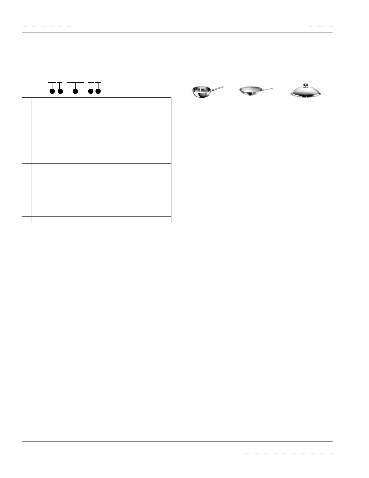
Proper Induction Cookware ............................................................................................51
Condition ...............................................................................................................................................51
Round bottom Wok pans.................................................................................................................. 51
Material ................................................................................................................................................... 52
BOIL TEST: Testing the Performance of Cookware ................................................................... 52
Size of Pan .............................................................................................................................................. 52
Placing Pan On A Cook Zone ...........................................................................................53
Power Control ...................................................................................................................55
Power Level Settings .......................................................................................................................... 55
Automatic Pan Detection, No Pan No Heat ....................................................................56
Indicator Lamp Signals ....................................................................................................56
When Appliance Is Idle.....................................................................................................56
Maintenance Safety—Disclaimer .................................................................................................. 57
Dangerous Electrical Voltage .......................................................................................................... 57
Maintenance Safety—Cleaning ..................................................................................................... 57
Personal Protection ............................................................................................................................58
Daily Cleaning and Maintenance ....................................................................................59
Glass Cleaning ...................................................................................................................................... 59
Stainless Steel case ............................................................................................................................. 59
Visual Inspection of Silicone Seal .................................................................................................. 59
Weekly Cleaning and Maintenance ................................................................................59
Air intake filters .................................................................................................................................... 59
Yearly Maintenance ..........................................................................................................59
Section 5
Troubleshooting
Dangerous Electrical Voltage .......................................................................................................... 60
Common Problems ...........................................................................................................60
Symptoms .........................................................................................................................60
Boil Test ............................................................................................................................. 60
Troubleshooting Without Error Code / Flash Code ........................................................61
Troubleshooting — Error Code / Flash Code ..................................................................61
Wearable Parts List ...........................................................................................................63
6 Part Number 4532415 Rev 5 12/15

Section 1
General Information
Description of Product
Built with a robust construction, our induction appliances
are compact and powerful with the revolutionary RTCS®
or RTCSmp® Technology (Realtime Temperature Control
System).
The RTCS®/RTCSmp® Technology monitors continuously in
realtime, the energy supply, temperature of the cook zone,
and the state of the components such as the induction coil.
This monitoring system ensures the most efficient energy
transfer, as well as maximizes safety:
• Safety functions such as Pan Detection and Boil Dry
Protection are therefore guaranteed.
• The appliance generates power only when a pan is in
contact with the cook zone surface.
• When a malfunction occurs, the integrated fault
diagnostic system reports the malfunction instantly.
The unique RTCSmp® Module-Line are engineered for
building the most flexible kitchen operation. The ModuleLine Family offers a wide selection of cooking surfaces: dual
or quad cook zones with round, full or a combination of
round and full induction coils. In addition, griddle, braising
pan, and wok cooking options are also available.
The components are compact and low profile. The
induction generator can be installed up to 3 meters or 10
feet away from the cooking surface or away from the high
heat area of the island suite. All power and communication
connections can be connected conveniently through plug
connections.
Application
The RTCS®/RTCSmp® induction appliances are designed to
be incorporated into a custom-built counter or an island
suite. See section 2 Installation.
You can use your appliance for many applications
throughout the day, such as cooking, warming up,
keeping warm, flambéing and roasting of food. All these
applications are possible because:
• Temperature control is instantaneous and precise.
Instant energy transmission from inverter coil to the
bottom of cookware, allows for fast startup time.
• High power is possible for braising application and
quick sauté.
• High power also means you can heat up a large
stockpot quickly (3.5kW coil or above).
• Cooking surface fitted with full coils: Several large or
small pans can be placed on one cook zone at the same
time. A small pot engages only 3.5kW power and a large
pot engages the full 7.0kW power.
• Cooking surface fitted with round coils: One pan is used
for each cook zone.
Compliances
• North American models:
ETL recognized* in compliance with UL 197, CSA C22.2
No.109, NSF-4. Complies with FCC part 18, ICES-001
*See section 2 Installation.
• CE models comply with the latest European Norms:
EN 60335-1, EN 60335-2-36, EN 62233 (EMC/EMV)
Part Number 4532415 Rev 5 12/15 7
General Information Section 1
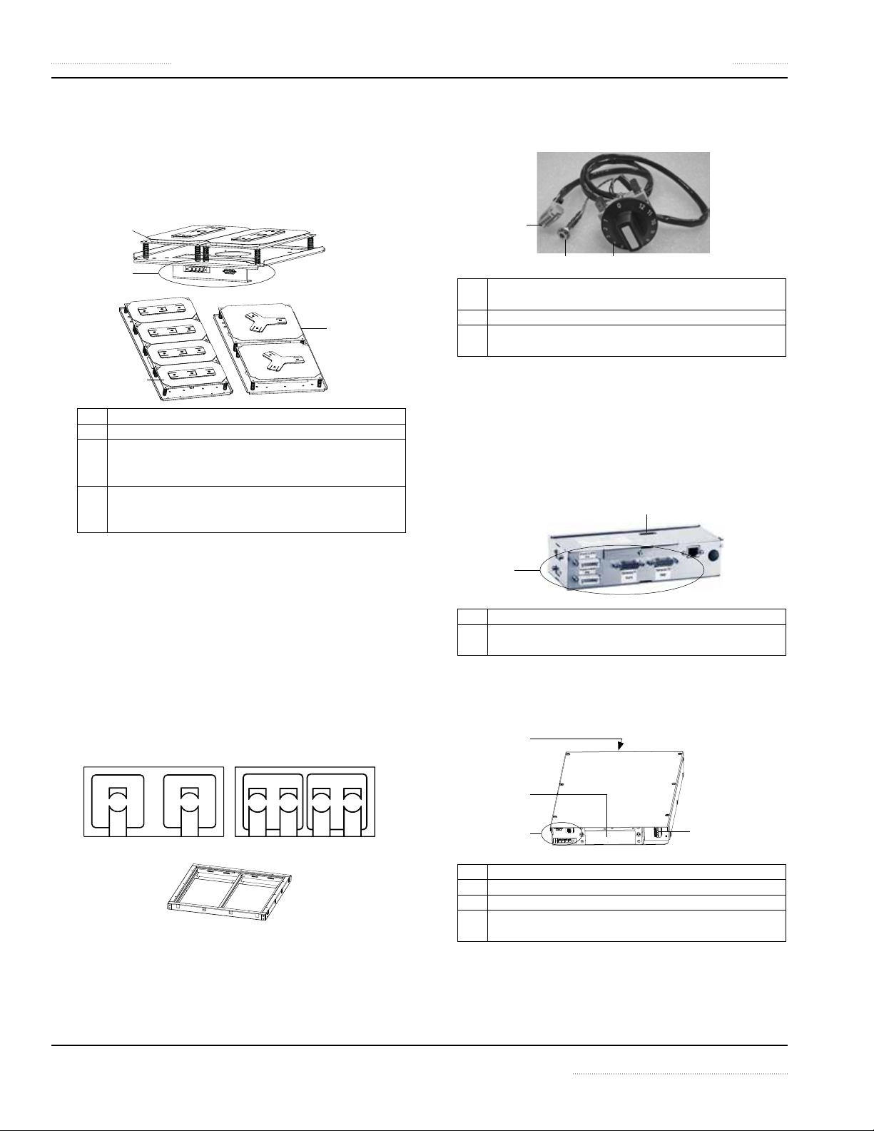
Components and Features
1. Coil Carrier Sheet (Induction Coil and Sensor
Assemblies)
Multiple versions available:
round coil (RU) or full coil (FL) in single, dual, quad, or
combined RU+FL configurations.
1.2
1.1
1.4
1.3
1.1 Cable connectors for coil and sensor cables.
1.2 Induction coil and sensor assembly.
1.3 Full coil (FL): Rectangular in shape. Each cook-zone
consists of two coils. More than one pan can be placed
on a single cook zone at the same time.
1.4 Round coil (RU): Round coils have higher power
density. Each cook zone consists of one coil. Only one
pan can be placed on a single cook zone.
4. Operating Unit
4.3
4.14.2
4.1 Rotary power switch, allows for continuously variable
power adjustment. Dial is marked 0 to 12 power levels.
4.2 Indicator lamp
4.3 1-meter [39.4”] long cable, to connect to the Control
Unit.
5. Control unit
• Communication and diagnostic hub for the
induction equipment.
• Mounting brackets are provided.
• 2 versions available:
IN/MO7000/10000, IN/MO7000/14000
5.2
2. Ceran® Glass-Top
• 6mm thick. 5 sizes available:
• Dual: 360x360x6mm; 650x375x6mm;
720x360x6mm
• Quad: 650x650x6mm; 720x720x6mm
• Included: silicone gaskets (not shown) for
installation.
• Glass-top pattern matches the corresponding coil
version underneath: Round coil (2.1, below) or full
coil (2.2, below).
2.1 2.2
3. Installation Frame
• Installation frame is provided to mount both the
coil carrier sheet and glass-top.
• 5 sizes available.
5.1
5.1 Cable connectors.
5.2 Service interface, provides service technician a wireless
connection to diagnose problems.
6. Induction generator
• 4 versions available: IN/MO7000FL, IN/MO14000FL,
IN/MO7000, IN/MO10000
6.3
6.2
6.1
6.1 Cable connectors.
6.2 Fresh air intake.
6.3 Hot air exhaust vent. Refer to the dimensional drawing.
6.4 Power supply connection.
Power supply cable is NOT INCLUDED.
6.4
8 Part Number 4532415 Rev 5 12/15

Section 1 General Information
Serial Plate Location
7. Cable Kit
• Cable kit voltage versions: 208V or 400V
• Standard, 2.5-meter cable kit, includes:
• Coil Cable, 2.5-meter [98”]
• CAN/BUS RJ-45 Cable, 3-meter [118”]
• Sensor Cable, 1-meter [39”]
• Fan Cable is included where applicable.
• Options, 4-meter cable kit, includes:
• Coil Cable, 4-meter [157.5”]
• CAN/BUS RJ-45 Cable, 5-meter [197”]
• Sensor Cable, 1-meter [39”]
• Fan Cable is included where applicable.
• Option, 6-meter cable kit, includes:
• Coil Cable, 6-meter [236.2”]
• CAN/BUS RJ-45 Cable, 7-meter [276.6”]
• Sensor Cable, 1-meter [39”]
• Fan Cable is included where applicable.
• There are different cable kits for Round coil (RU)
components and Full coil (FL) components.
• RU cable kit descriptions: IN/MO7000/10000-
360 or IN/MO7000/10000
• FL cable kit descriptions: IN/MO7000FL-360 or
IN/MO14000
The serial plate specifies the model number, serial number,
and electrical specifications of the appliance.
See illustration below for location.
Model Number
The model number is located on the serial plate.
NOTE: The model number on the serial plate is the model
number of the induction generator.
This manual covers the following models:
IN/MO 7000 IN/MO 7000FL
IN/MO 10000 IN/MO 14000FL
READING THE MODEL NUMBER
Example:
1 Product Series 1 IN = Built-In Line
2 Product Series 2 MO = Module Line
3 Power (Watt) 7000, 10000
4 Type of Induction Coil Standard, Round Coil
IN/MO 7000
2
1
3
IN/MO 7000FL
2
1
FL = Full Coil (Rectangular)
3 4
Marketing Identifier
Marketing identifier is used when specifying the product
on specification sheet and other marketing literature. This
product is identified as:
Dual Models Quad Models
MO/DU 7000-360/650/720 MO/QU 14000-650/720
MO/DU 10000-360/650/720 MO/QU 20000-650/720
MO/DU 7000-360FL MO/QU 21000-720
MO/DU 14000-360/650/720FL MO/QU 24000-720
MO/QU 28000-650/720FL
READING THE MARKETING IDENTIFIER
Example:
1 Product Series MO = Module Line
2 Multi-Zone DU = Dual Cook Zones
3 Power (Watt) 7000, 10000, 14000, 20000,
4 Glass Size, length (mm) 360, 650, 720
5 Type of Induction Coil Standard, Round Coil
MO/DU 7000-650FL
2
1
3 4
QU = Quad Cook Zones
21000, 28000
FL = Full Coil (Rectangular)
5
Part Number 4532415 Rev 5 12/15 9
General Information Section 1
Serial Number Accessories
The serial number is located on the serial plate.
READING THE SERIAL NUMBER
Example:
1 Type of induction appliance:
2 Last two(2) or three(3) digits of the appliance article number
3 A sequential number:
4 Month of manufacture: 01, 02, 03, 04, ...
5 Year of manufacture: 2014 (14), 2015 (15), ...
BA01 . 00014 . 1214
2
1
BA = Base Line Series (Counter-Top Cook-Top)
IN = Built-In Series
WO = Counter Wok Series
MO = Module Line Series
HO = Hold Line Series
GR = Griddle Line Series
or part number that can be found on the invoice or the
packing slip.
• A 4-digit sequence number indicates that the
appliance is not RTCS® nor RTCSmp®.
• A 5-digit sequence number indicates that the
appliance is either a RTCS® or RTCSmp® appliance.
• A RTCSmp® appliance is marked as such on the serial
plate.
3 4 5
Induction cooking equipment requires Induction Ready
pans to operate. Consult your equipment supplier for a list
of our pan selection and prices.
10 Part Number 4532415 Rev 5 12/15

Section 2
Installation
IMPORTANT INSTALLATION SAFETY AND ELECTRICAL REQUIREMENTS
Warning
n
Safety and Electrical Requirements
This appliance component requires additional features and components to comply with appliance and electrical
standards.
It is the responsibility of the customer and installer to interpret and comply with all applicable national and
regional health codes, safety and electrical standards in your jurisdiction.
This product requires the addition of:
• A suitable non-flammable electrical enclosure; a means to conceal and protect components and wiring.
• Grounding and bonding to the enclosure.
• An appliance rating plate that includes end manufacturer information.
• Investigation by local electrical authority. Warning, caution labels and other markings required by electrical
and safety standards could be provided by local authority.
Depending on the application and configuration of this product(s), consider the addition of:
• Field supply connection terminals (terminal block).
• Branch circuit protection (breakers).
• Fans, ventilation or cooling systems and controls.
Warning
n
The induction appliance is designed to be installed into a custom built counter or an island suite.
The appliance includes a number of components that have to be installed separately. Customers are responsible for
providing proper installation mounting for the components.
Read ALL SECTIONS carefully, comply with all requirements listed and ensure inspection is done by qualified personnel.
Part Number 4532415 Rev 5 12/15 11
Installation Section 2
INSTALLATION SAFETYDISCLAIMER
DANGER
Installation must be carried out by registered installation
contractors only.
The contractors are responsible for interpreting all
instructions correctly and performing the installation
in compliance with all applicable national and local
regulations.
The warning signs and serial plates on the equipment
must strictly be followed.
Warning
n
This equipment is intended for indoor use only. Do not
install or operate this equipment in outdoor areas.
Warning
n
To avoid instability, the installation area must be capable
of supporting the combined weight of the equipment
and food product. The equipment must be level side to
side and front to back.
Caution
,
Consultants, fabricators and designers must consult their
counter-top suppliers when designing an appropriate
support structure and clearance for the counter-top and
the installation.
Notice
Induction equipment that is not installed correctly will
have warranty voided.
INSTALLATION SAFETYCLEARANCE AND
VENTILATION
DANGER
Risk of Fire or Shock or Equipment Failure
All minimum clearances must be maintained. Air intake
vents and exhaust vents must not be blocked or be
restricted by the installation.
Caution
,
This equipment must only be operated under an
approved ventilation system in accordance with all
applicable national and local regulations. Exceptions
may apply.
Notice
The maximum ambient temperature for the
induction appliance to operate must not exceed
40°C [104°F].
Failure to provide adequate ventilation will cause
the appliance to overheat, to reduce power, or to
shutdown.
NOTE: Always maintain enough space between and
around the equipment for maintenance and service.
INSTALLATION SAFETYELECTRICAL
DANGER
All electrical connections must be carried out by a
certified electrical contractor, who is responsible for
the correct rating and installation of the appliance. The
contractor has to comply with all legal safety regulations
and all applicable national and local electrical codes.
Warning
n
Markings and warning labels mounted directly on the
equipment must be observed at all times and kept in a
fully legible condition.
Warning
n
This equipment must be positioned so that the plug is
accessible unless other means for disconnection from
the power supply, such as circuit breaker or disconnect
switch, is provided.
Warning
n
CE Induction Appliance only: If ground fault current
protective switches are used, they must be provided
with selective activation and designed for a minimum
fault current of 30mA.
Notice
Ensure the supply voltage and the line current match
the specifications given on the serial plate affixed to the
appliance. Wrong voltage will damage the appliance. A
stable power supply must be provided.
Notice
Always refer to the serial plate on the appliance to verify
the electrical data. When the data listed on the serial
plate is different than that listed in this manual, contact
the manufacturer or the authorized representative.
12 Part Number 4532415 Rev 5 12/15
Section 2 Installation
Notice
All cables must be routed, protected and tension free.
PERSONAL PROTECTION
DANGER
All utilities (gas, electric, water and steam) must be
OFF to all equipment and locked out of operation
according to national/regional, as well as company
approved practices during installation, maintenance
and servicing. Always allow appliance to cool.
DANGER
Use appropriate safety equipment during installation,
maintenance and servicing.
DANGER
Never stand, sit, or lean on the equipment! They are
not designed to hold the weight of an adult, and may
collapse or tip if misused in this manner.
DANGER
To avoid cardiac pacemaker malfunction, consult your
physician or pacemaker manufacture about effects of
electromagnetic field on your pacemaker.
Warning
n
Markings and warning labels mounted directly on the
equipment must be observed at all times and kept in a
fully legible condition.
Warning
n
Risk of burns from high temperatures. You may get burnt
if you touch any of the parts during operation. Surfaces
close to the cooking area including side panels may get
hot enough to burn skin. Use extreme caution to avoid
coming in contact with hot surfaces or hot grease. Wear
personal protective equipment.
Caution
,
Use caution when handling metal surface edges of all
equipment.
Part Number 4532415 Rev 5 12/15 13
Installation Section 2
1
5
2
3
4
6
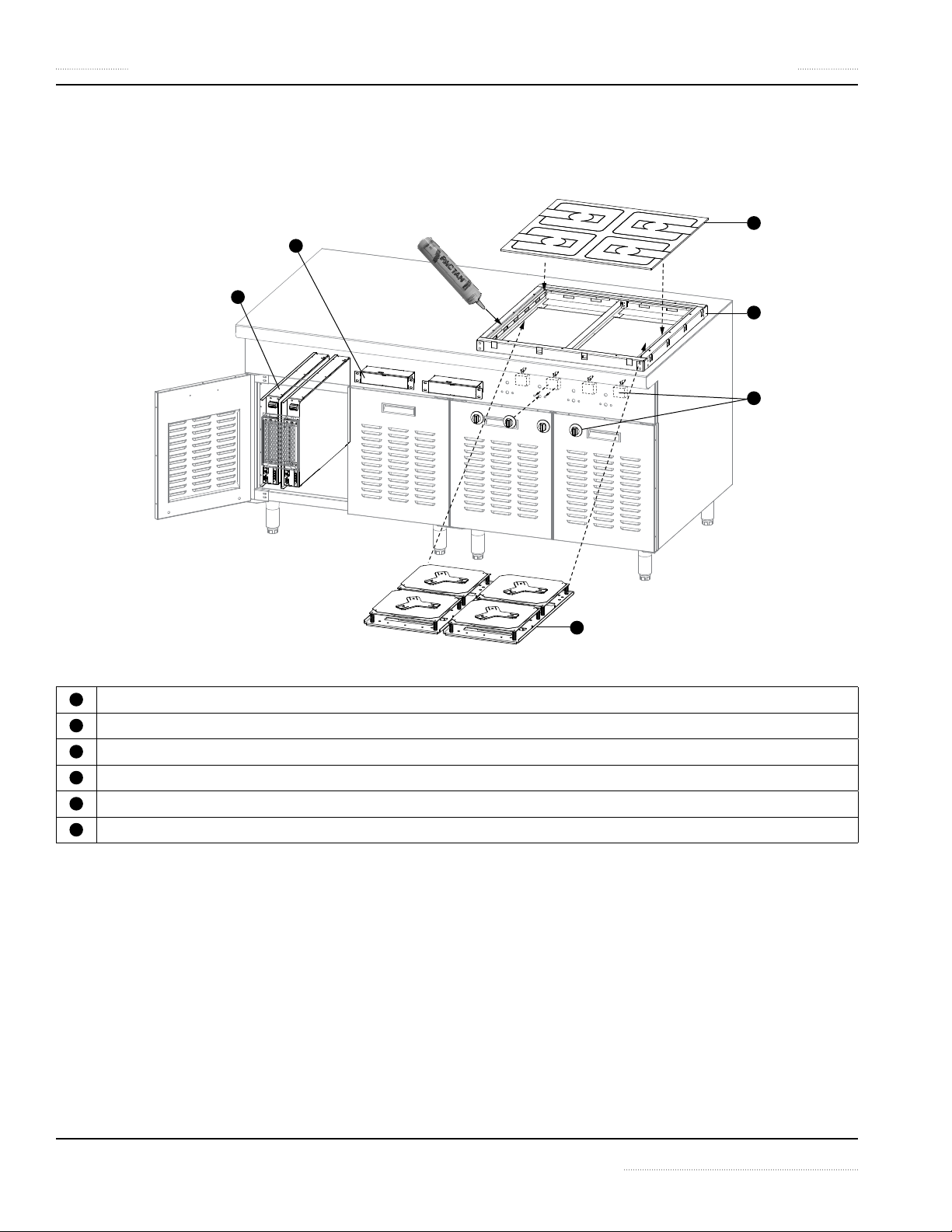
Exploded View of a Typical Installation
Shown below, model MO/QU. For a complete list of components, see the components chart for your specific model. Tube of
silicone sealant (part number 70000015) shown for installation is not provided.
Glass cooktop
1
Mounting Frame (for typical installation on 1.5 - 3mm [16 - 10 gauge] thick counter-tops]
2
Coil Carrier Sheets (Induction Coil and Sensor Assembly)
3
Induction Generator
4
Control Unit
5
Operating Unit
6
14 Part Number 4532415 Rev 5 12/15

Section 2 Installation
Planning for Installation
The induction appliance is designed to be installed
into a custom built counter or an island suite. You
1
must plan ahead for the location, ventilation and
electrical requirements for the induction appliance.
See sections:
• Electrical safety at the beginning of this chapter.
• Cabinet Requirements on page 15
• Specifications on page 21
At the design stage, it is important to consult your
electrical contractor to ensure your cabinet design
2
and installation will meet all applicable electrical and
safety codes. See sections:
• Electrical safety at the beginning of this chapter.
• Electrical Specifications on page 29
• Electrical Installation on page 37
Your custom built counter or island suite must have
proper support structure for the countertop,
3
the appliance and cooking vessels. The support
structure will depend on the installation method,
the countertop material and thickness. See sections:
• Typical Applications on page 17
We recommend consulting a mechanical
contractor to advise on the structure, ventilation
4
methods and the overall design. See sections:
• Cabinet Requirements on page 15
• Typical Applications on page 17
• Specifications on page 21
The equipment includes a number of components
that have to be installed separately. Ensure
5
you understand the clearance requirements and
installation methods. See sections:
• Exploded View of a Typical Installation on page
14
• Specifications on page 21
• Installation Instructions on page 32
An exploded view of a typical installation is provided.
It is very important to seal all installation gaps with
6
silicone sealant to prevent water ingress.
• Exploded View of a Typical Installation on page
14
• Installation Instructions on page 32
Cabinet Requirements
Read and understand all installation
safety instructions at the beginning of
Section 2 Installation.
PLACE THE INDUCTION APPLIANCE AWAY FROM
1
HEAT AND MOISTURE
• Similar to other electronic equipment, induction
equipment is sensitive to moisture and high heat.
Recommendations
• Do not position the air intake vent near steam or
heat exhaust of another appliance.
• Never place your induction equipment next to
any grease generating, heat generating or steam
emitting equipment, such as oven, deep fryer,
pasta cooker, steamer and water bath.
• Never install or place your induction equipment
near or on a hot surface.
• Isolate and protect the electronic equipment and
wiring with a separate compartment. Install heat
shield such as an insulated wall or air gap.
PROVIDE ADEQUATE VENTILATION AND MANAGE
2
AIRFLOW
• Maximum ambient temperature for the
induction appliance to operate must not exceed
40°C [104°F].
• Minimum opening for fresh air supply required per
induction generator: total sum of 6500mm2 [10.08
square inches].
• Opening for exhaust should be at least as big as
the intake vent. Minimum, a total sum of 6500mm
[10.08 square inches] per induction generator.
• Fresh air intake and hot exhaust vents must not be
blocked or restricted by the installation.
• Ensure the appliance does not pull in hot ambient
air or steam from another appliance.
• The intake air and exhaust air must not mix. Hot
exhaust must not be pulled back into the appliance
through the fresh air intake opening.
• Air intake filter, custom built or provided, must be
easily accessible for weekly inspection or cleaning.
Recommendations
• Install fresh air filter on the cabinet.
• Install louvered opening or ventilation gaps to aid
air movement and to allow hot exhaust to escape.
• Depending on the air path and the amount of
natural air movement, install ventilation fan on the
2
Part Number 4532415 Rev 5 12/15 15
Installation Section 2
cabinet to pull quickly hot exhaust away from the
electronic equipment. As an alternative, provide a
separate exhaust air plenum.
NOTE: In a situation that when ventilation fan
cannot be installed on the cabinet, you must provide
ventilation gaps with size of minimum 323 square
centimeters [50 square inches] per dual built-in
appliance.
NOTE: Additional air filters, ventilation fans, cooling
controls, and air ducts are the responsibility of the
customer and installer.
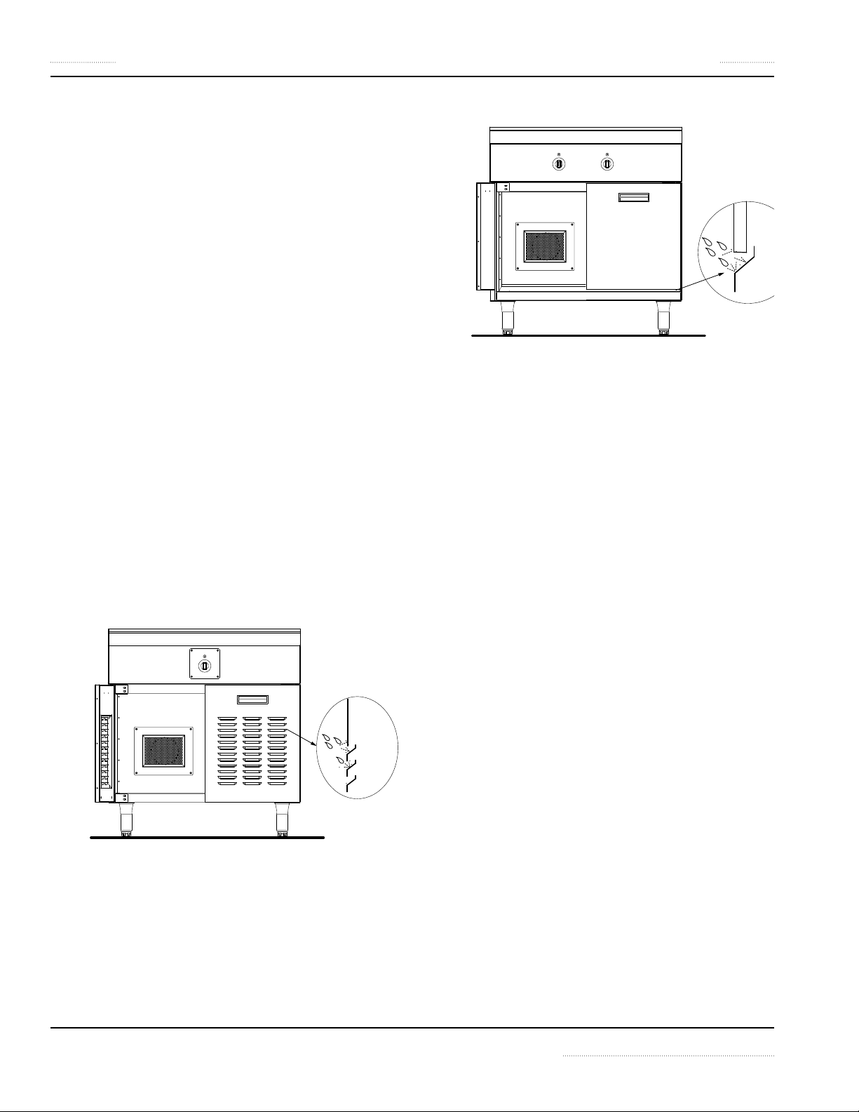
PREVENT WATER INGRESS
3
• Any ingress of water will damage the electronic
equipment.
Recommendations
• Consider cleaning method and how it might
impact your cabinet design.
• All mating surfaces and installation gaps between
the countertop and the appliance must be bonded
and sealed properly with silicone.
• Design and construct ventilation gaps in such a
ways that they would prevent water ingress.
Examples below shown that bent flanges are
created behind louvered openings (Example 1)
or ventilation gaps (Example2) to deflect water
splashes.
Example 1.
Example 2.
ELIMINATE FIRE HAZARDS
4
• Comply with all ventilation and installation
clearances.
• Keep the appliance away from combustible
materials, vapors or liquids.
• Final cabinet construction and installation must
comply with all applicable national and local
electrical and safety codes.
PROVIDE SAFE DISCONNECT FROM POWER
5
SUPPLY
• The appliance is intended to be permanently
connected to fixed wiring. Other means for
disconnection from power supply, such as circuit
breaker or disconnect switch, must be accessible.
Consult your local authorities or your electrical
contractor for details.
PROVIDE SERVICE CLEARANCE
6
• Provide enough space and service access for
technicians to perform maintenance and service.
16 Part Number 4532415 Rev 5 12/15

Section 2 Installation
Typical Applications
In this section you will find examples of the most common
installations for the induction appliance.
A quad model is shown in the illustrations as an example.
When multiple appliances are installed into the same
counter, special attention must be paid to the ventilation
and electrical requirements. Use the list of features below as
your design guideline to ensure a proper cabinet is used for
the application and installation.
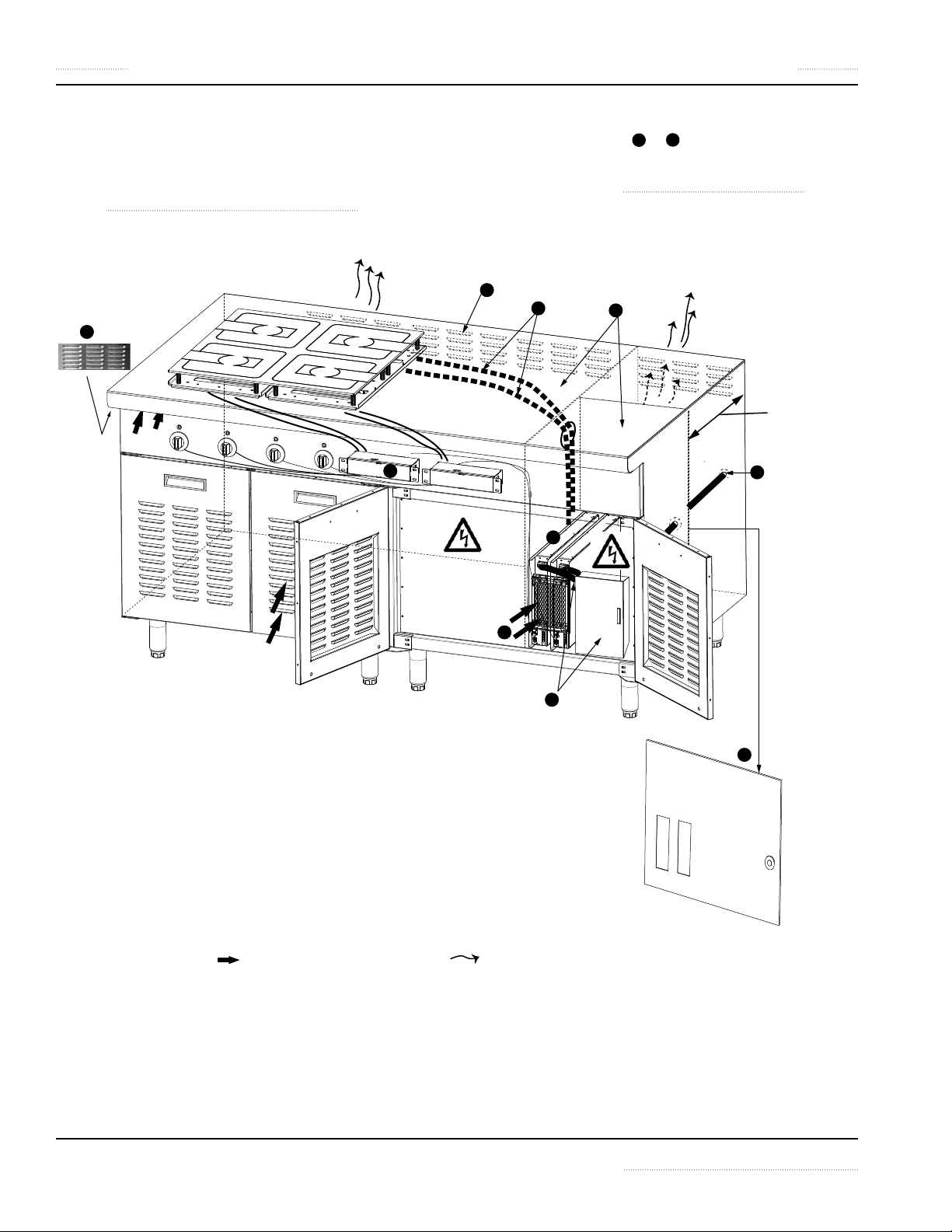
IMPORTANT DESIGN FEATURES
Install the Induction Generator in a separate
compartment away from heat and moisture. Ensure to
have adequate ventilation:
1
The air intake vent is located at the front and the
intake air is filtered by an air filter mounted on the
cabinet.
2
The exhaust vent is located at the back of the
generator. Consider to create a baffle to prevent the
exhaust air from mixing with the fresh intake air. As an
alternative, create an exhaust air plenum.
In each of the application example, a baffle is placed
behind the generator and the exhaust is vented into
a separate channel or chamber and then outside the
cabinet. Distance between the exhaust openings and
any obstruction is minimum 40mm [1.57”].
3
Louvered openings of ventilation fan allow exhaust
to escape.
4
Louvered openings or ventilation gap facilitate
proper air-flow.
Safe electrical environment:
5
An enclosed compartment protects the electronic
appliance and wiring from the environment.
Personnel are also protected from the electronics and
the electrical cables.
6
It is important that the coil cables are routed
separately from other communication and power
cables.
7
The appliance is intended to be permanently
connected to fixed wiring. Other means for
disconnection from power supply, such as circuit
breaker or disconnect switch, must be accessible.
NOTE: National and local electrical codes dictate the
electrical requirements. Consult your local authorities
or your electrical contractor for details.
8
Supply inlet / conduit opening shown.
Flexible configuration:
9
The control unit can be installed in multiple
orientations. See Cut-out Dimensions: Holes and Studs
for Control / Operation unit on page 27
10
The generator can be installed up to 3-meter [10fee] from the cooktop. See Electrical Cables on page
30.
Water-tight environment:
11
Mating surfaces between the appliance and
coutertop are sealed with silicone (not shown, see
Installation Instructions on page 32).
12
Design and construct ventilation gaps that
could prevent water ingress (not shown, see Cabinet
Requirements on page 15).
Part Number 4532415 Rev 5 12/15 17
Installation Section 2
9
1
5
2
3
4
6
7
8
10
APPLICATION EXAMPLE 1
• The equipment is built into a large, enclosed
compartment. There is ample of space for installation
and service.
descriptions of items 1 to 10 in illustration.
• For minimum fresh air intake and exhaust openings for
each generator, see Electrical Cables on page 30
• See Important Design Features on page 17 for the
min.
40mm [1.57”]
Indicates the direction of airflow for fresh air. Indicates the direction of airflow for exhaust air.
Application Example 1: Equipment Built Into A Large Compartment.
18 Part Number 4532415 Rev 5 12/15
Section 2 Installation
7
9
4
2
6
1
5
3
8
10
5
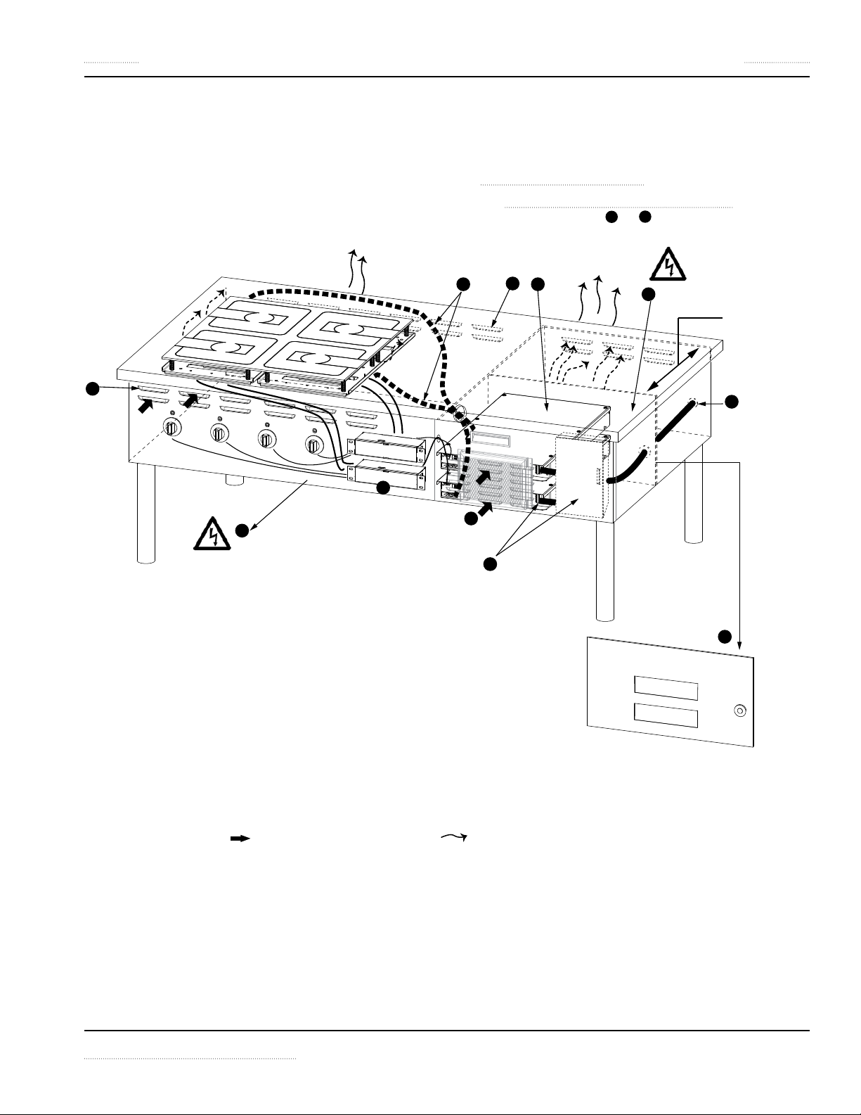
APPLICATION EXAMPLE 2
• The equipment is built into a small, enclosed
compartment of a counter with an open base. The
compact profile of the appliance is ideal for a front of
house cooking station.
• The generators are enclosed in a small electrical
compartment. It is important to ensure that there
is adequate ventilation to maintain an operating
temperature of below 40°C [104°F]. For minimum fresh
air intake and exhaust openings for each generator, see
Electrical Cables on page 30
• See Important Design Features on page 17 for the
descriptions of items 1 to 10 in illustration.
min.
40mm [1.57”]
Indicates the direction of airflow for fresh air. Indicates the direction of airflow for exhaust air.
Application Example 2: Equipment Built Into A Counter With An Open Base.
Part Number 4532415 Rev 5 12/15 19
Installation Section 2
7
9
4
2
6
1
5
3
8
10
5
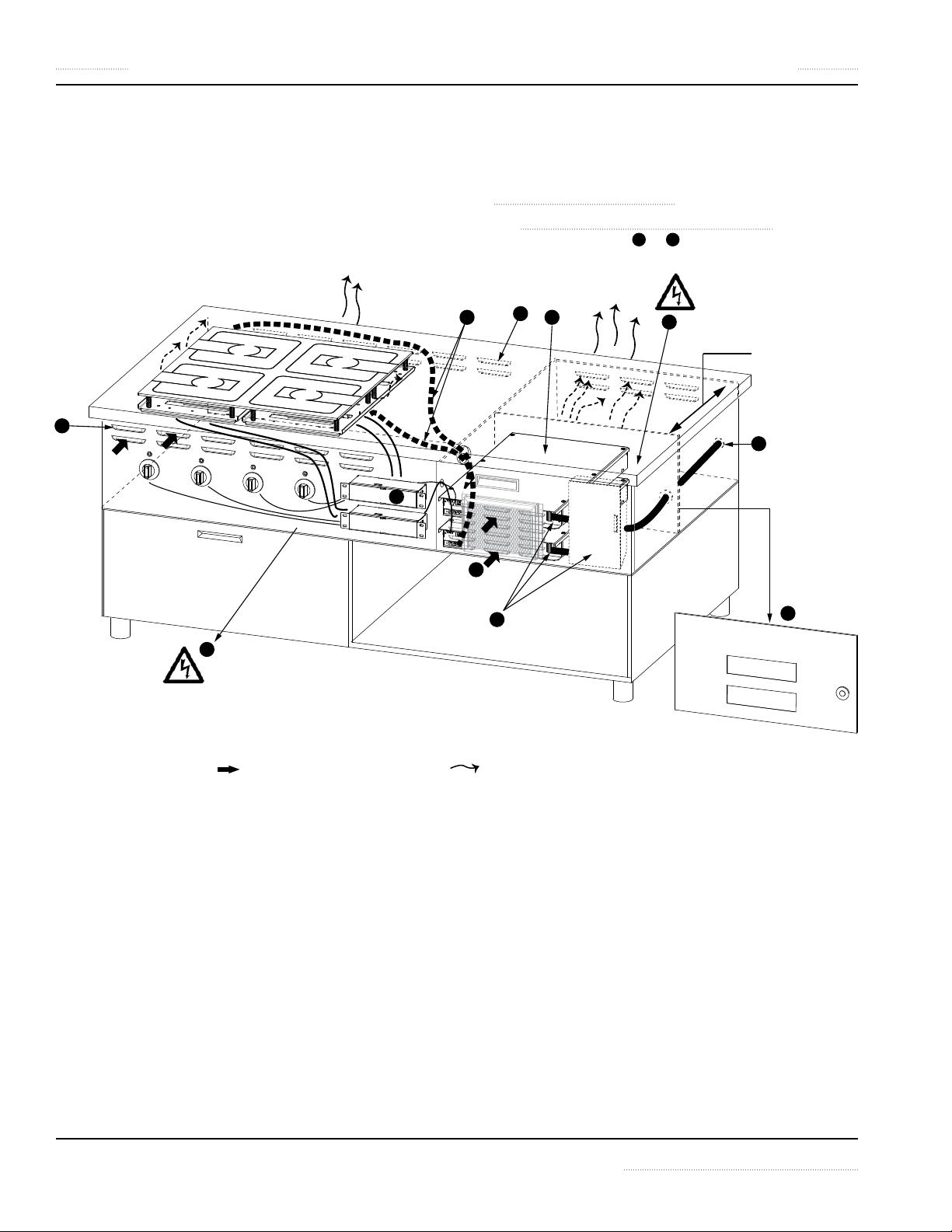
APPLICATION EXAMPLE 3
• This is an application of a low profile design, combined
with additional functionalities such as cold or dry
storage base. The induction appliance and wiring are
isolated and protected in the upper compartment.
• The generators are enclosed in a small electrical
compartment. It is important to ensure that there
is adequate ventilation to maintain an operating
temperature of below 40°C [104°F]. For minimum fresh
air intake and exhaust openings for each generator, see
Electrical Cables on page 30
• See Important Design Features on page 17 for the
descriptions of items 1 to 8 in illustration.
min.
40mm [1.57”]
Application Example 4: Equipment Built Into A Counter With Other Built-In Functionalities.
Indicates the direction of airflow for fresh air. Indicates the direction of airflow for exhaust air.
20 Part Number 4532415 Rev 5 12/15
 Loading...