

Garland GI-MO/DU 7000, GI-MO/DU 7000 (FL), GI-MO/DU 10000, GI-MO/DU 14000 (FL), GI-MO/QU 14000 Installation And Operation Manual
...
INSTALLATION AND
OPERATION MANUAL
GARLAND INDUCTION
MODULE-LINE COOKTOPS
DUAL/QUAD
with RTCSmp TECHNOLOGY
Real-time Temperature Control System
multi-point sensing
CE models comply with the latest European
Norms:
EN 60335-1, EN 60335-2-36, EN 62233 (EMC/EMV)
North American models: ETL listed in
compliance with UL 197, CSA C22.2 No.109, NSF-4
Complies with FCC part 18, ICES-001
FOR YOUR SAFETY
DO NOT STORE OR USE GASOLINE OR OTHER
FLAMMABLE VAPORS OR LIQUIDS IN THE VICINITY
OF THIS OR ANY OTHER APPLIANCE
Models:
GI-MO/DU 7000
GI-MO/DU 7000 (FL)
GI-MO/DU 10000
GI-MO/DU 14000 (FL)
GI-MO/QU 14000
GI-MO/QU 20000
GI-MO/QU 21000
GI-MO/QU 24000
GI-MO/QU 28000 (FL)
PLEASE READ ALL SECTIONS OF THIS MANUAL AND
RETAIN FOR FUTURE REFERENCE.
THIS PRODUCT HAS BEEN CERTIFIED AS COMMERCIAL
COOKING EQUIPMENT AND MUST BE INSTALLED BY
PROFESSIONAL PERSONNEL AS SPECIFIED
INSTALLATION AND ELECTRICAL CONNECTION MUST
COMPLY WITH CURRENT CODES:
IN CANADA – THE CANADIAN ELECTRICAL CODE PART 1
AND / OR LOCAL CODES.
IN USA – THE NATIONAL ELECTRICAL CODE ANSI / NFPA
– CURRENT EDITION.
WARNING
IMPROPER INSTALLATION, ADJUSTMENT, ALTERATION,
SERVICE OR MAINTENANCE CAN CAUSE PROPERTY
DAMAGE, INJURY, OR DEATH. READ THE INSTALLATION,
OPERATING AND MAINTENANCE INSTRUCTIONS
THOROUGHLY BEFORE INSTALLING OR SERVICING THIS
EQUIPMENT
Users are cautioned that maintenance and repairs must be performed by a Garland authorized service agent using only genuine
Garland replacement parts. Garland will have no obligation with respect to any product that has been improperly installed,
adjusted, operated or not maintained in accordance with national and local codes and/or installation instructions provided with
the product or any product that has its serial number defaced, obliterated or removed, and/or which has been modified or
repaired using unauthorized parts or by unauthorized service agents. For a list of authorized service agents and/or genuine
replacement parts, please visit our website at www.garland-group.com for USA and Canada. For international customers, please
visit www.manitowocfoodservice.com. The information contained herein, including design and part specifications, may be
superseded and is subject to change without notice.
Visit our Video Gallery at
www.Garland-Group.com
Part # 4532415 Rev 1 (12/12/13) © 2013 Garland Commercial Ranges Limited
Installation and Operation Manual RTCSmp Built-In Module-Line Dual/Quad Cooktops
Warning
WARRANTY
Our warranty statements for induction products are available on-line. Please visit our
website at www.garland-group.com/minisite/service to download the latest revision. If you
might have any questions, please contact Garland.
USING THIS MANUAL
This manual contains important information regarding safety, installation, operation,
maintenance, and troubleshooting. They must be read entirely and carefully by the
installers and operators before the equipment is installed and taken into operation. This
manual must always be available for reference at the place of operation.
Throughout this manual, the induction unit type “RTCSmp Built-In Module Line” is referred
to as “induction unit”.
DESCRIPTION OF WARNING SYMBOLS
This symbol alerts you to a hazardous situation that WILL or COULD
cause serious bodily harm or death. Be alert and implement relevant
safety precautions.
CAUTION
CONTACTS
Garland Commercial Ranges Ltd.
1177 Kamato Road, Mississauga, Ontario, Canada. L4W 1X4
T: 1-905-624-0260 | F: 1-905-624-5669 | www.garland-group.com
USA Sales, Parts and Service 1-800-424-2411
Canadian Sales 1-888-442-7526
Canada or USA Parts/Service 1-800-427-6668
International Sales and Service www.ManitowocFoodservice.com
This dangerous voltage warning symbol indicates a risk of electric shock
and hazards from dangerous voltage.
This symbol alerts a hazardous situation, which if not avoided, COULD
cause minor to moderate personal injury or property damage. The
relevant safety precautions MUST be implemented at all times.
Electromagnetic field.
Risk of fire or electric shock
Do not open
To reduce the risk of fire or electric shock,
do not remove or open cover.
No user serviceable parts inside.
Refer servicing to qualified personnel.
2 Part # 4532415 Rev 1 (12/12/13)

Installation and Operation Manual RTCSmp Built-In Module-Line Dual/Quad Cooktops
CONTENTS
1 Safety Requirements .............................................................................................................. 5
1.1 Risk Involved By Disregarding Safety Information .................................................................................................. 5
1.2 Safety Instructions for Operator ..................................................................................................................................... 5
1.3 Improper Use of the Equipment ..................................................................................................................................... 6
1.4 Unauthorized Modification and Use of Spare Parts ................................................................................................ 6
1.5 Pan Detection ......................................................................................................................................................................... 7
1.6 Cooking Zone Monitoring ................................................................................................................................................. 7
2 Application, Components Overview ..................................................................................... 8
2.1 Application .............................................................................................................................................................................. 8
2.2 Components and Features ............................................................................................................................................... 8
3 Dimensions and Technical Specifications ........................................................................... 10
3.1 Rating Plate ...........................................................................................................................................................................10
3.2 Nomenclature and Models .............................................................................................................................................10
3.3 Models and Components Charts ..................................................................................................................................10
3.4 Electrical Specifications ....................................................................................................................................................11
3.5 Operating Conditions .......................................................................................................................................................12
3.6 Compliances .........................................................................................................................................................................12
4 Installation ............................................................................................................................ 13
4.1 Compartment Protection ................................................................................................................................................13
4.2 Induction Generator ..........................................................................................................................................................14
4.2.1 Location ..............................................................................................................................................................14
4.2.2 Ventilation .........................................................................................................................................................14
4.2.3 Dimensions ........................................................................................................................................................15
4.3 Control Unit and Operation Unit/Power Switches ................................................................................................16
4.3.1 Location ..............................................................................................................................................................16
4.3.2 Ventilation .........................................................................................................................................................16
4.3.3 Mounting Methods ........................................................................................................................................16
4.3.4 Dimensions – Control Unit ..........................................................................................................................16
4.3.5 Dimensions Guide (Holes/Studs) ..............................................................................................................17
4.4 Coil Carrier Sheet, Ceran Glass and Mounting Frame ..........................................................................................17
4.4.1 Location & Ventilation ...................................................................................................................................17
4.4.2 Dimensions – Mounting Frame [for glasstop size 360x360mm] ..................................................18
4.4.3 Dimensions – Mounting Frame [for glasstop size 375x650mm] ..................................................19
4.4.4 Dimensions – Mounting Frame [for glasstop size 650x650mm] ..................................................19
4.4.5 Dimensions – Mounting Frame [for glasstop size 360x720mm] ..................................................20
4.4.6 Dimensions – Mounting Frame [for glasstop size 720x720mm] ..................................................20
4.4.7 Installation Steps .............................................................................................................................................21
4.5 Models, Components and Cable Connections ........................................................................................................24
4.5.1 CHART 1 – Module-Line Round Coil Dual Models ..............................................................................24
4.5.2 CHART 2 – Module-Line Round Coil Quad Models ............................................................................25
4.5.3 CHART 3 – Module-Line Full Coil Dual Models ....................................................................................26
4.5.4 CHART 4 – Module-Line Full Coil Quad Models ..................................................................................27
4.5.5 CHART 5 – Module-Line Full and Round Coil Quad Models ...........................................................28
4.6 Electrical Installation .........................................................................................................................................................29
5 Function Test ......................................................................................................................... 31
6 Operating Instructions ......................................................................................................... 32
6.1 Proper Induction Cookware ...........................................................................................................................................32
Part # 4532415 Rev 1 (12/12/13) 3

Installation and Operation Manual RTCSmp Built-In Module-Line Dual/Quad Cooktops
Proper Placement of Cookware .................................................................................................................................... 33
6.2
6.3 Power Control ...................................................................................................................................................................... 34
6.4 No Pan No Heat ................................................................................................................................................................... 35
6.5 When Unit is Not In Use ................................................................................................................................................... 35
7 Cleaning ................................................................................................................................. 36
8 Maintenance .......................................................................................................................... 37
9 Important Rules .................................................................................................................... 37
10 Troubleshooting ................................................................................................................... 38
10.1 Common causes for induction unit failure ............................................................................................................... 38
10.2 Problems and Possible Causes ...................................................................................................................................... 39
10.3 Troubleshooting with Error Codes (for Service Technicians) ............................................................................ 40
4 Part # 4532415 Rev 1 (12/12/13)
Safety Requirements RTCSmp Built-In Module-Line Dual/Quad Cooktops
1 Safety Requirements
WARNING This product contains chemicals known to the State of California to cause cancer.
Installation and servicing of this product could expose you to airborne particles of glass
wool / ceramic fibers. Inhalation of airborne particles of glass wool / ceramic fibers is
known to the State of California to cause cancer.
IMPORTANT Warning labels mounted directly on the induction unit must be observed at all times and
kept in a fully legible condition.
IMPORTANT To ensure your working environment is safe, you must follow all of the safety instructions
contained in this manual, the existing national regulations for accident prevention with
electrical systems, as well as any relevant company-specific safety instructions.
The induction unit should only be used if and only if the
installation of the electrical system is fitted by an approved
installation contractor in accordance with specific national and
local regulations.
1.1 Risk Involved By Disregarding Safety Information
Disregarding the safety instructions may cause harm to people, the surroundings, and the induction unit. Garland
is not responsible for any damages or personal injury caused by failure to observe the safety requirements.
Risks involved when disregarding safety precautions may include:
• Death or injury caused by electric shock.
• Injury due to burns from contacting overheated cooking surface, cookware, or oil and grease.
• Damage to the induction unit caused by using unsuitable cookware.
1.2 Safety Instructions for Operator
Please follow the following rules to avoid personal injuries and property damages:
• When the unit is in use, heat transfers from the cookware to the glass-top; the glass-top can become hot. To
avoid burn injuries, do not touch the heating area when the unit is in use.
• The induction unit heats up cookware and cooks food quickly. Do not leave an empty pan on the unit and do
not leave the unit unattended during operation.
• If the glass-top is cracked or broken, switch off the induction unit immediately and if possible and safe,
disconnect it from the power supply. Do not touch any parts inside the induction unit.
• Persons with cardiac pacemakers should consult their doctors whether they are safe near an induction unit.
• Ensure no liquid can enter into the induction unit. Do not let water or food overflow the cooking area. Do not
use hoses to clean or power wash the induction unit or its vicinity.
• Do not put any other items on the glass-top except non-empty induction cookware.
Part # 4532415 Rev 1 (12/12/13) Page 5

Safety Requirements RTCSmp Built-In Module-Line Dual/Quad Cooktops
o Do not leave any object such as paper, cardboard, or cloth between the cookware and the cooking
surface, as this might start a fire.
o Metallic objects are heated up very quickly when placed on the induction unit when the unit is in
use. Do not place any objects such as closed cans, aluminum foil, cutlery, jewelry, or watches on the
induction unit when the unit is in operation.
o Do not place credit cards, phone cards, tapes, or any objects sensitive to magnetism on the cooking
surface.
o Do not place plastic vessels and aluminum objects such as aluminum foil on the glass-top.
• The induction unit has an internal air-cooling system. Do not block the air inlet and outlet slots with objects
such as containers. Any air obstruction could cause the unit to be overheated and to switch off.
• Use only induction suitable cookware with proper sizes and made of proper material. The induction suitable
cookware should also be in good condition without any uneven, arched or partially detached bottoms.
• Switch the unit OFF if you take the cookware away for a while. This will prevent the heating process to start
automatically and unintentionally when a pan is placed back on the heating area. If any person needs to use
the induction unit, he/she will have to turn the unit ON intentionally.
1.3 Improper Use of the Equipment
The reliability of the induction unit can only be guaranteed when it is used properly. The induction unit must
always be operated within the limits provided in the technical specifications. Please refer to section 9 Important
Rules of using induction equipment.
1.4 Unauthorized Modification and Use of Spare Parts
Please contact Garland if you intend to make any changes on the induction unit. For safety reasons, always use
genuine parts and accessories approved by Garland. Any unauthorized modification as well as any installation of
unapproved components will void all warranty.
6 Part # 4532415 Rev 1 (12/12/13)

Safety Requirements RTCSmp Built-In Module-Line Dual/Quad Cooktops
1.5 Pan Detection
Energy is transferred to cookware if and only if the induction system detects a suitable pan on the heating area.
The green indicator light signals to communicate the Pan Detection process:
• When the unit is ON without any pan on the glass-top, the green indicator light flashes; the unit is in pan
detection mode.
• As soon as a pan is put on the glass-top, the heating process is engaged and the indicator light stops
flashing and remains bright. However, the indicator light will keep flashing if the unit is not detecting any
pan or an unsuitable pan is placed on the glass-top.
NOTE: Pan with a bottom diameter smaller than 5”(12 cm) is not detected by the system.
When you remove the pan from the heating area, power transfer to the pan is stopped immediately. If the pan is
put back in the heating zone, the selected power will be transferred to the pan again.
After switching the unit off, there is no heat retained inside the unit.
1.6 Cooking Zone Monitoring
Each cooking zone is monitored by multiple temperature sensors beneath the glass-top. The sensors can detect
overheated empty pans or overheated oil and grease. When this occurs, the system stops the energy supply to
the pan. You must turn the unit off and let it cool down before restarting it.
To avoid burn injuries, do not touch the unit when a pan is
CAUTION
overheated and take all the necessary precautions when
removing the overheated pan.
Part # 4532415 Rev 1 (12/12/13) Page 7
Application, Components Overview RTCSmp Built-In Module-Line Dual/Quad Cooktops
Can be installed up to 10 feet away from other components. | All electrical
connections can be accessed externally through plug connections. | Closed
connections. | Compact design and easy to install using special installation
2 Application, Components Overview
2.1 Application
The unique RTCSmp Module-Line Cooktops are specially engineered for building the most flexible kitchen
operation. The Module-Line Family offers a wide selection of cooking surfaces: single, dual, quad cooktops with
round, full or a combination of round and full induction coils. In addition, griddle, braising pan, and wok cooking
options are also available.
These RTCSmp units provide numerous great features including fast heat up time, precise temperature
monitoring and control, temperature consistency, ease of use and maintenance. To guarantee the induction
units’ reliability and performance, please observe all safety, installation, and operation requirements mentioned in
this manual.
2.2 Components and Features
Built with a robust construction, the RTCSmp Induction Module-Line Cooktop is
modular and powerful with the revolutionary RTCSmp-Technology (Realtime
Temperature Control System with Multi-Point sensing). The RTCSmp Technology
Each built-in Module-Line concept consists of: induction generator(s), control unit(s), coil carrier sheet(s) with coils
and sensors, operation unit(s) with rotary switch(es), 6mm thick Ceran glass-top(s), mounting frame(s) with
silicone gaskets, and cables.
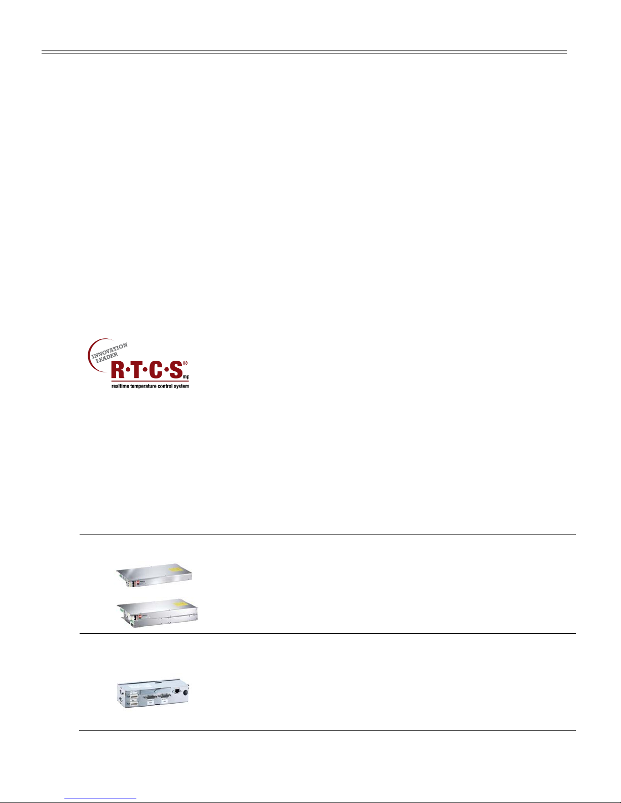
Induction Generator:
OR
monitors the energy supply, the state of the induction coil, power board, CPU,
and the cooking zone in realtime. RTCSmp also limits the energy supply during
peak load and its special control eliminates interference noises.
The module-line models include a number of components which allow for
optimal flexibility in designing an efficient kitchen. The unique features of each
component are outlined below. See also chapter 3 Dimensions and Technical
Specifications.
aluminum housing with an integrated cooling fan to keep electronics cool. |
Integrated air guiding system to direct exhaust air out of the housing.
Types:
IN/MO 7000FL, IN/MO 14000FL, IN/MO 7000, IN/MO 10000
Control Unit:
8 Part # 4532415 Rev 1 (12/12/13)
Information and diagnostic hub for the whole induction unit. | IR interface with
diagnostic system for service. | Connections to other unit components via plug
tabs/brackets.
Types:
IN/MO7000/10000, IN/MO7000/14000, IN/MO14000
Application, Components Overview RTCSmp Built-In Module-Line Dual/Quad Cooktops
Installation/mounting frame is supplied for flush mounting the coil carrier
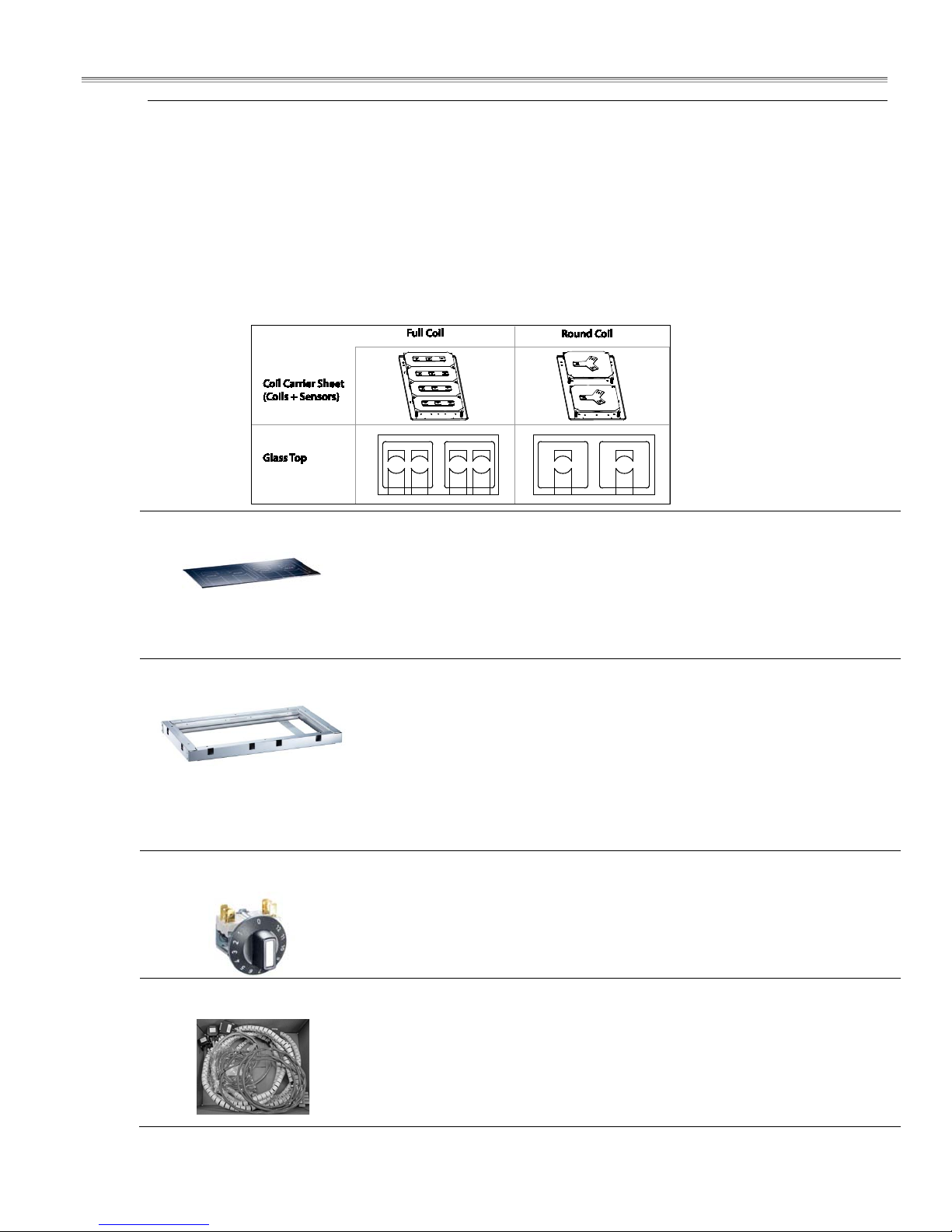
Coil Carrier Sheet:
Multiple options available: round or full coil in single, dual, quad, or combination of round/full coil
configurations. | Compact and low profile design.
Full Coil (FL): Rectangular in shape. Several large or small pans can be placed on one surface at the same
time.
Round Coil: One pan is used for each heat-zone. Round coils have higher power density and energy
efficiency.
Visual differences between full and round coil carrier sheets and the corresponding glass-tops:
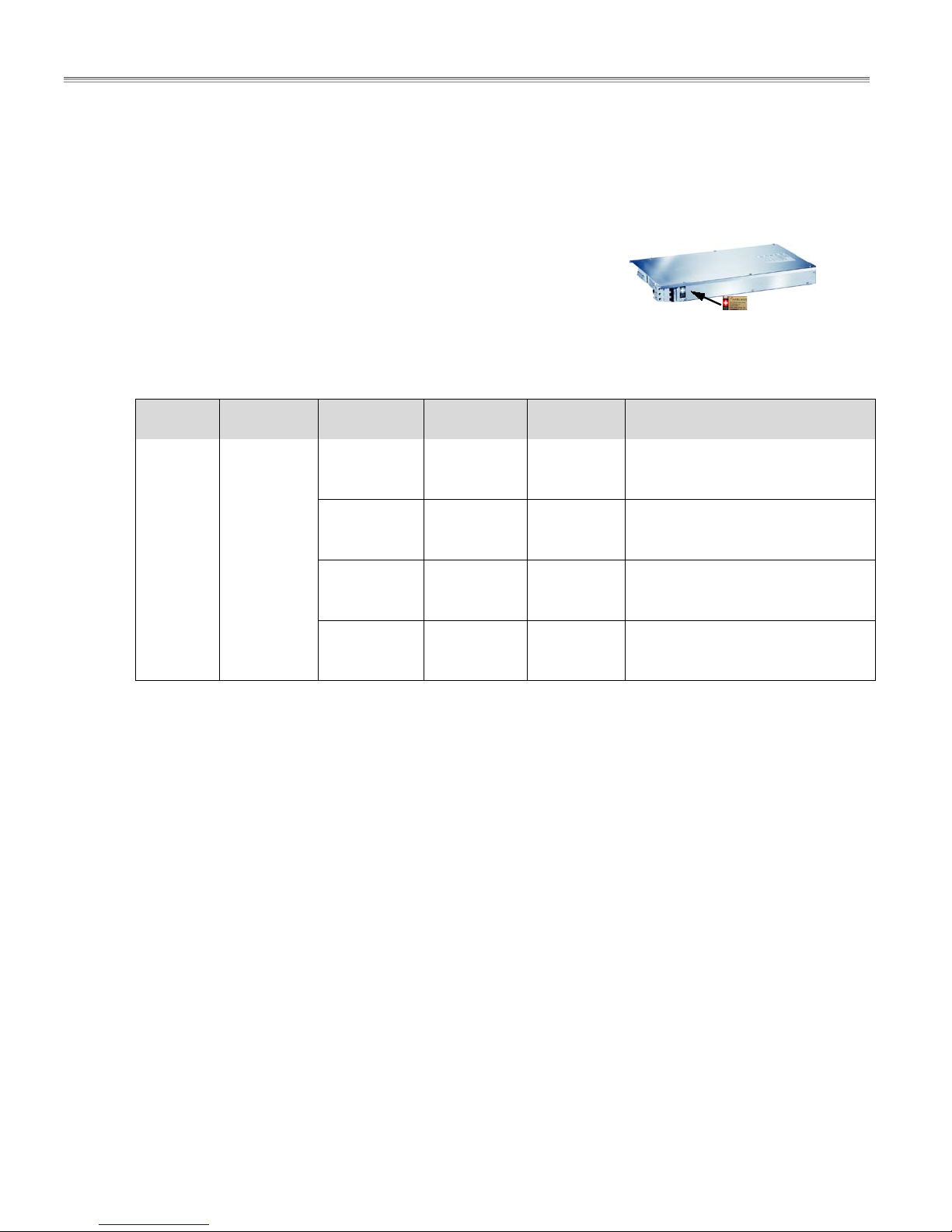
Glass-Top:
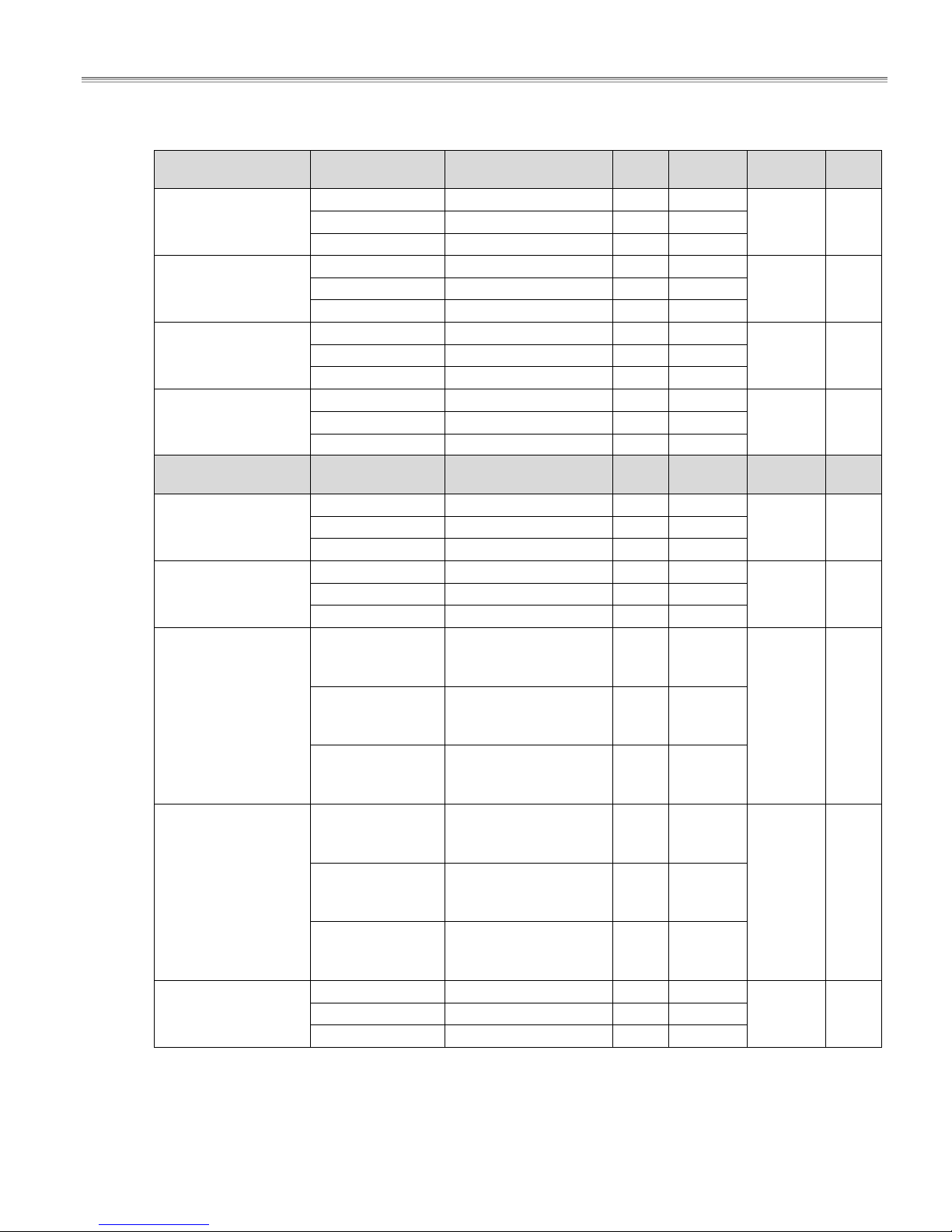
Installation Frame:
Operation Unit:
6mm thick Ceran glass-top. | Easy to clean and maintain. | Glass-top patterns
match the corresponding coil versions underneath: Full-Coil or Round-Coil.
Types:
Dual Square: 360x360x6mm
Dual Retangular: 650x375x6mm; 720x360x6mm
Quad: 650x650x6mm; 720x720x6mm
sheet(s) and glass-top. | Silicone gaskets included.
Five Sizes of Frames:
- for -360 or -360FL dual models with 360x360x6mm glasstop
- for -650 or -650FL dual models with 650x375x6mm glasstop
- for -720 or -720FL dual models with 720x360x6mm glasstop
- for -650 or -650FL quad models with 650x650x6mm glasstop
- for -720 or -720FL quad models with 720x720x6mm glasstop
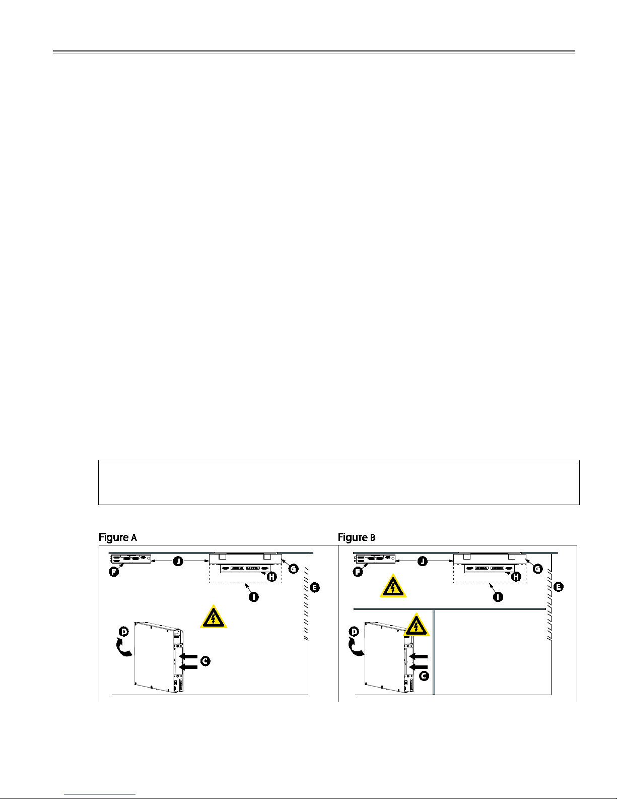
The power switch (Operation Unit) regulates the temperature in power levels 1
to 12. | Simple to operate; adjust the temperature setting simply by turning the
knob. | LED light indicator signals the ON/OFF process, pan detection process
and error codes.
Cable Kit:
2.5-meter cable kit(s) for 208V or 440V is included. Each kit includes cables for
induction coils, sensors, and CAN/BUS connections. Fan cables are included
where applicable.
Options:
4-meter Cable Kit (208V); 4-meter Cable Kit (400V); 6-meter Cable Kit (208V); 6meter Cable Kit (400V)
Part # 4532415 Rev 1 (12/12/13) Page 9
Dimensions and Technical Specifications RTCSmp Built-In Module-Line Dual/Quad Cooktops
3 Dimensions and Technical Specifications
3.1 Rating Plate
The rating plate contains important information such as model number,
serial number, and electrical specifications. The rating plate is affixed to
the side of the induction generator, next to the mains connection.
3.2 Nomenclature and Models
Brand ,
Product
GI =
Garland
induction
Series Style/
Function
MO =
module-line
DU = Dual 7000, 10000 360 x 360,
DU = Dual
with FL=Full
coil(at end)
QU = Quad 14000,
QU = Quad
with FL=Full
coil(at end)
Power (Watt) Glass Size
7000, 14000 360 x 360,
20000,
21000, 24000
28000 650 x 650,
3.3 Models and Components Charts
Models and Components Charts are provided in section 4 Installation. These charts list the components and the
electrical connections among them for each model. Quantities are specified on the charts. For details in
dimensions of the components, refer to the drawings in section 4 Installation.
(mm)
650 x 375,
720 x 360
650 x 375,
720 x 360
650 x 650,
720 x 720
720 x 720
Models
GI-MO/DU 7000/10000 -360
GI-MO/DU 7000/10000 -650
GI-MO/DU 7000/10000 -720
GI-MO/DU 7000/14000-360FL
GI-MO/DU 14000-650FL
GI-MO/DU 14000-720FL
GI-MO/QU 14000/20000-650
GI-MO/QU 14000/20000-720
GI-MO/QU 21000/24000-720
GI-MO/QU 28000-650FL
GI-MO/QU 28000-720FL
10 Part # 4532415 Rev 1 (12/12/13)
Dimensions and Technical Specifications RTCSmp Built-In Module-Line Dual/Quad Cooktops
21000W(Round Coil
24000W(Round Coil
3.4 Electrical Specifications
#
Model - DUAL Voltage Power
208 V AC/ 3Ph/ 60Hz 7000W(2x3500 W)/ 22A 1 AWG 10
GI-MO/DU 7000-360FL
440 V AC/ 3Ph/ 50Hz 7000W(2x3500 W)/ 10A 1 1.5mm2
GI-MO/DU 7000-360
GI-MO/DU 7000-650
GI-MO/DU 7000-720
GI-MO/DU 10000-360
GI-MO/DU 10000-650
GI-MO/DU 10000-720
GI-MO/DU 14000-360FL
GI-MO/DU 14000-650FL
GI-MO/DU 14000-720FL
Model - QUAD Voltage Power
208 V AC/ 3Ph/ 60Hz 7000W(2x3500 W)/ 22A 1 AWG 10
400 V AC/ 3Ph/ 50Hz 7000W(2x3500 W)/ 11A 1 1.5mm2
440 V AC/ 3Ph/ 50Hz 7000W(2x3500 W)/ 10A 1 1.5mm2
208 V AC/ 3Ph/ 60Hz 10000W(2x5000 W)/ 30A 1 AWG 8
400 V AC/ 3Ph/ 50Hz 10000W(2x5000 W)/ 16A 1 2.5mm2
440 V AC/ 3Ph/ 50Hz 10000W(2x5000 W)/ 15A 1 2.5mm2
208 V AC/ 3Ph/ 60Hz 14000W(4x3500 W)/ 22A 2 AWG 10
400 V AC/ 3Ph/ 50Hz 14000W(4x3500 W)/ 11A 2 1.5mm2
440 V AC/ 3Ph/ 50Hz 14000W(4x3500 W)/ 10A 2 1.5mm2
208 V AC/ 3Ph/ 60Hz 14000W(4x3500 W)/ 22A 2 AWG 10
GI-MO/QU 14000-650
GI-MO/QU 14000-720
400 V AC/ 3Ph/ 50Hz 14000W(4x3500 W)/ 11A 2 1.5mm2
440 V AC/ 3Ph/ 50Hz 14000W(4x3500 W)/ 10A 2 1.5mm2
208 V AC/ 3Ph/ 60Hz 20000W(4x5000 W)/ 30A 2 AWG 8
GI-MO/QU 20000-650
GI-MO/QU 20000-720
440 V AC/ 3Ph/ 50Hz 20000W(4x5000 W)/ 15A 2 2.5mm2
Circuits
#
Circuits
Conductor
Size
Conductor
Size
# Coils
2
rectangular
coils
2 round
coils
2 round
coils
4
rectangular
coils
# Coils
4
round coils
4
round coils
#Cook-
Zones
1 400 V AC/ 3Ph/ 50Hz 7000W(2x3500 W)/ 11A 1 1.5mm2
2
2
2
#Cook-
Zones
4
4 400 V AC/ 3Ph/ 50Hz 20000W(4x5000 W)/ 16A 2 2.5mm2
GI-MO/QU 2100-720
GI-MO/QU 2400-720
GI-MO/QU 28000-650FL
GI-MO/QU 28000-720FL
208 V AC/ 3Ph/ 60Hz
2x3500W + Full Coil
3 AWG 10
4x3500 W)/ 22A
21000W(Round Coil
400 V AC/ 3Ph/ 50Hz
2x3500W + Full Coil
3 1.5mm2
4x3500 W)/ 11A
21000W(Round Coil
440 V AC/ 3Ph/ 50Hz
2x3500W + Full Coil
3 1.5mm2
4x3500 W)/ 10A
208 V AC/ 3Ph/ 60Hz
440 V AC/ 3Ph/ 50Hz
24000W(Round Coil
2x5000W + Full Coil
4x3500 W)/ 30A
24000W(Round Coil
2x5000W + Full Coil
4x3500 W)/ 16A
2x5000W + Full Coil
4x3500 W)/ 15A
3
3
3
(1x) AWG 8
(2x) AWG 10
(1x) 2.5mm
(2x) 1.5mm
(1x) 2.5mm
(2x) 1.5mm
208 V AC/ 3Ph/ 60Hz 28000W(8x3500 W)/ 22A 4 AWG 10
400 V AC/ 3Ph/ 50Hz 28000W(8x3500 W)/ 11A
440 V AC/ 3Ph/ 50Hz 28000W(8x3500 W)/ 10A
4
4
1.5mm2
1.5mm2
2 round + 4
rectangular
coils
2 round + 4
2
rectangular
2
coils
2
2
rectangular
coils
4
4 400 V AC/ 3Ph/ 50Hz
8
4
Part # 4532415 Rev 1 (12/12/13) Page 11

Dimensions and Technical Specifications RTCSmp Built-In Module-Line Dual/Quad Cooktops
3.5 Operating Conditions
Max. Tolerance of Nominal Supply Voltage +6 /-10 %
Network Impedance (Zmax.) 0.25Ω
Supply frequency 50/60 Hz
Amperage Nominal Value — 400V, 3Ph 10A for the 7kW generator (4 x 1.5mm2)
15A for the 10kW generator (4 x 2.5mm
2 x 10A for the 14kW generator (2 x (4 x 1.5mm
Amperage Nominal Value — 208V, 3Ph 20A for the 7kW generator (4x AWG 10)
29A for the 10kW generator (4x AWG 8)
2 x 20A for the 14kW generator (2 x (4 x AWG 10))
Ingress Protection class IP X0
Maximum Ambient Temperature In Storage > -4°F to +158°F (-20°C to +70°C)
In Operation >+ 41°F to +104°F (+5°C to +40°C)
Maximum Relative Air Humidity In Storage > 10% to 90%
In Operation > 30% to 90%
Temperature/Power Regulator Potentiometer 10 kOhm
LED Indicator Lamp 24VDC / max. 40mA (Green)
Clearance from materials for generator Min. 1.57”(40mm) for air intake and exhaust openings
Min. 0.39”(10mm) for side clearance
Min. Induction Cooking Pan Diameter 5” (12cm)
Max. Air Flow of Fan is 70.63 cfm (120 m3 /h), Fresh Air Inlet Opening of 10.08 sq. in. (6500 mm2) is required.
2
)
2
))
3.6 Compliances
• North American models:
ETL listed in compliance with UL 197, CSA C22.2 No.109, NSF-4. Complies with FCC part 18, ICES-001
• CE models comply with the latest European Norms:
EN 60335-1, EN 60335-2-36, EN 62233 (EMC/EMV)
12 Part # 4532415 Rev 1 (12/12/13)
Installation RTCSmp Built-In Module-Line Dual/Quad Cooktops
4 Installation
IMPORTANT
• Kitchen designers and installation contractors are responsible for designing and installing correctly the
appropriate support structures and ventilation system for the cooking equipment.
• When designing kitchen cabinets for the induction equipment, please take into account all installation
requirements, including factors such as: ease of electrical installation, size of the power conductor, and
length of the wires.
• The installation, including electrical installation, must be carried out by registered installation contractors
only. The contractors are responsible for interpreting all instructions correctly and performing the
installation in compliance with national and local regulations. The warning signs and rating plates on the
cooking equipment must strictly be followed.
• Read ALL SECTIONS carefully, comply with all requirements listed and ensure all inspection is done by
qualified personnel.
• Refer to the technical data given in chapter 3 Dimensions and Technical Specifications.
• Induction equipment that is not installed correctly will have warranty voided. See Warranty, p.2.
4.1 Compartment Protection
To protect the induction unit and wiring, we recommend isolating the generator, the coil carrier sheets, and the
wires in separate electrical compartments inside the cabinet.
The illustrations below show two installation versions. In Figure A, all module-line components are installed inside
one single compartment and the wires are exposed. In Figure B, the interior space of the cabinet is divided. The
coil carrier sheet, the control unit and their wiring are protected inside the upper compartment; the generator
and its wiring are protected inside the lower compartment. Extra storage space can also be created.
IMPORTANT: To ensure reliability of the induction unit, the cabinet/compartments must have sufficient
ventilation for the exhaust. Build up of hot exhaust air will cause the unit to reduce power or to
switch-off.
Part # 4532415 Rev 1 (12/12/13) Page 13

Installation RTCSmp Built-In Module-Line Dual/Quad Cooktops
The call-outs in the illustrations show:
(C) Hot air exhaust from the generator.
(D) Air intake through the air intake opening on the generator.
(E) Louvered air exhaust opening installed on the cabinet.
(F) Control Unit mounted to the underside of the countertop.
(G) Mounting frame.
(H) Coil Carrier Sheet inserted into the Mounting Frame.
( I ) CLEARANCE: minimum 10cm / 3.94”. See section 4.3 Coil Carrier Sheet, Ceran Glass and Mounting
Frame.
(J) Ensure the distance between the control unit and the coil carrier sheet is less than 80cm/31.5”.
4.2 Induction Generator
4.2.1 Location
• The induction generator can be installed around heat-producing equipment such as an oven, if and only
if the ambient temperature is below 104°F (40°C). An external fan must be used to remove the air away
from the induction unit. NOTE: Additional fans and cooling controls are the responsibility of the installer.
• Prevent moisture, hot ambient air or greasy fume being drawn in by the induction generator, especially
when the equipment is side-by-side or in the vicinity of a fryer or oven.
• Keep all the combustible materials, vapors or liquids away from the generator.
• Ensure the installed location of the generator is safe from any ingress of liquid into the immediate
vicinity.
• Ensure the cable connections are accessible for service.
4.2.2 Ventilation
Proper cool air intake and ventilation is essential to the reliability and functioning of the induction unit. Please
ensure all requirements listed below are met:
• The induction generator has an air intake and an air exhaust openings. Ensure these openings are not
blocked. Clearance from obstructions: minimum 1.57”(40mm) for the air intake and exhaust openings;
minimum 0.39”(10mm) for the sides.
• The air intake temperature must not exceed 104°F (40°C). If the generator is installed directly under the
coil or in the same chamber of the cabinet as the coil, ensure the ventilation system will keep the
ambient temperature for operation below 104°F (40°C).
• Maximum air flow of the fan is 70.63 cfm (120 m
sq. in. (6500 mm
• An optimal air circulation and air flow must not be restricted by the installation.
3
2
) is required around the fresh air inlet.
per hour) and therefore a minimum opening of 10.08
• When installing the units, ensure the intake air and exhaust air are conducted separately. The in-take air
and exhaust air must not mix. To avoid build-up of hot exhaust air inside the counter, draw the exhaust
air out of the counter, or provide a separate exhaust air plenum. Build up of hot exhaust air will cause the
induction unit to reduce power or to switch-off.
• Ensure the induction unit does not take in hot ambient air from other surrounding units and appliances,
especially when the installed location of the unit is close to heat generating equipment such as a fryer or
an oven.
14 Part # 4532415 Rev 1 (12/12/13)
 Loading...