

Page 1
INSTALLATION AND
OPERATION MANUAL
GARLAND GF SENTRY SERIES
GAS RESTAURANT RANGES
All 24, 36, 48, & 60-inch wide models.
Français . . . . . . . . . . . . . . . . . . . . . . . . . . . . . . . . . . . . . . . . . . . . . . . . . . . . . . . . . . . . . . . . . . . . . . . . . . . . . . . . . . . . . . . . . . . . . . Page 21
Españo. . . . . . . . . . . . . . . . . . . . . . . . . . . . . . . . . . . . . . . . . . . . . . . . . . . . . . . . . . . . . . . . . . . . . . . . . . . . . . . . . . . . . . . . . . . . . Página 43
FOR YOUR SAFETY:
DO NOT STORE OR USE GASOLINE
OR OTHER FLAMMABLE VAPORS OR
LIQUIDS IN THE VICINITY OF
THIS OR ANY OTHER
APPLIANCE
WARNING:
IMPROPER INSTALLATION, ADJUSTMENT,
ALTERATION, SERVICE OR MAINTENANCE
CAN CAUSE PROPERTY DAMAGE, INJURY,
OR DEATH. READ THE INSTALLATION,
OPERATING AND MAINTENANCE
INSTRUCTIONS THOROUGHLY
BEFORE INSTALLING OR
SERVICING THIS EQUIPMENT
Users are cautioned that maintenance and repairs must be performed by a Garland authorized service agent using
genuine Garland replacement parts. Garland will have no obligation with respect to any product that has been
improperly installed, adjusted, operated or not maintained in accordance with national and local codes or installation
instructions provided with the product, or any product that has its serial number defaced, obliterated or removed, or
which has been modified or repaired using unauthorized parts or by unauthorized service agents. For a list of authorized
service agents, please refer to the Garland web site at http://www.garland-group.com. The information contained
herein, (including design and parts specifications), may be superseded and is subject to change without notice.
PLEASE READ ALL SECTIONS OF THIS MANUAL
AND RETAIN FOR FUTURE REFERENCE.
THIS PRODUCT HAS BEEN CERTIFIED AS
COMMERCIAL COOKING EQUIPMENT AND
MUST BE INSTALLED BY PROFESSIONAL
PERSONNEL AS SPECIFIED.
IN THE COMMONWEALTH OF MASSACHUSETTS
THIS PRODUCT MUST BE INSTALLED BY A
LICENSED PLUMBER OR GAS FITTER.
For Your Safety:
Post in a prominent location, instructions to be
followed in the event the user smells gas. This
information shall be obtained by consulting
your local gas supplier.
Garland Commercial Ranges, Ltd.
1177 Kamato Road, Mississauga, Ontario L4W 1X4 CANADA
Phone: 905-624-0260
Fax: 905-624-5669
Part # 4525587 Rev 4 (29 April 14)
General Inquires 1-95-624-0260
USA Sales, Parts and Service 1-800-424-2411
Canadian Sales 1-888-442-4526
Canada or USA Parts/Service 1-800-427-6668
Page 2

IMPORTANT INFORMATION
WARNING:
This product contains chemicals known to the State of California to cause cancer and/or birth defects or other reproductive harm. Installation and servicing of this product could expose you to airborne particles of glass wool/ceramic fibers. Inhalation of airborne particles of glass wool/ceramic
fibers is known to the State of California to cause cancer. Operation of this product could expose
you to carbon monoxide if not adjusted properly. Inhalation of carbon monoxide is known to the
State of California to cause birth defects or other reproductive harm.
Keep appliance area free and clear of combustibles.
Part # 4525587 Rev 4 (29 April 14)Page 2
Page 3

TABLE OF CONTENTS
IMPORTANT INFORMATION. . . . . . . . . . . . . 2
DIMENSIONS AND SPECIFICATIONS . . . . . 4
Base Model Designations & Total Input Rates . . 5
Clearances . . . . . . . . . . . . . . . . . . . . . . . . . . . . . . . . . . .5
Gas Pressure & Individual Burner Input Rates . . 6
North America . . . . . . . . . . . . . . . . . . . . . . . . . . . 6
CE & General Export . . . . . . . . . . . . . . . . . . . . . . 6
Reduced Input Rates . . . . . . . . . . . . . . . . . . . . . 6
Note: Manifold pressure is to measured at the
test spigot located on the 3/4” gas manifold
pipe.. . . . . . . . . . . . . . . . . . . . . . . . . . . . . . . . . . . . . 6
Australia . . . . . . . . . . . . . . . . . . . . . . . . . . . . . . . . . 7
Gas Inlet Size . . . . . . . . . . . . . . . . . . . . . . . . . . . . . . . . 7
CE Approved Gas Categories . . . . . . . . . . . . . . . . . 7
INTRODUCTION. . . . . . . . . . . . . . . . . . . . . . . . 8
Final Preparation . . . . . . . . . . . . . . . . . . . . . . . . . . . . 12
Optional Interconnect Gas Kit . . . . . . . . . . . . . . . 12
TESTING AND ADJUSTMENT . . . . . . . . . . . 13
Testing . . . . . . . . . . . . . . . . . . . . . . . . . . . . . . . . . . . . . 13
OPERATION. . . . . . . . . . . . . . . . . . . . . . . . . . . 14
Flame Failure Technology . . . . . . . . . . . . . . . . . . . 14
How Flame Failure Technology Works . . . . . . . .14
Burner Operation . . . . . . . . . . . . . . . . . . . . . . . . . . . 14
Open Top burners . . . . . . . . . . . . . . . . . . . . . . . . . . 14
Hot Tops and Front-Fired Target Tops . . . . . . . . 15
Ovens (Standard) . . . . . . . . . . . . . . . . . . . . . . . . . . . 15
Convection Ovens . . . . . . . . . . . . . . . . . . . . . . . . . . 16
Thermostat Controlled Griddles . . . . . . . . . . . . . 17
Griddle/Broiler . . . . . . . . . . . . . . . . . . . . . . . . . . . . . . 17
Rating Plate . . . . . . . . . . . . . . . . . . . . . . . . . . . . . . . . . . 8
Safety Information . . . . . . . . . . . . . . . . . . . . . . . . . . . 8
INSTALLATION. . . . . . . . . . . . . . . . . . . . . . . . . 9
Siting . . . . . . . . . . . . . . . . . . . . . . . . . . . . . . . . . . . . . . . . 9
Appliances Equipped With Casters . . . . . . . . . . . . 9
Appliances Equipped With Legs . . . . . . . . . . . . . . 9
Installing Shelf To Backguard . . . . . . . . . . . . . . . . . 9
Backguard With High Shelf Or Salamander
Mounting Instructions . . . . . . . . . . . . . . . . . . . . . . .9
Ventilation Air . . . . . . . . . . . . . . . . . . . . . . . . . . . . . . 10
Statutory Regulations . . . . . . . . . . . . . . . . . . . . . . . 11
Australia Speci c Clause . . . . . . . . . . . . . . . . . . . . . 11
Electrical Connection Settings
(Where Applicable) . . . . . . . . . . . . . . . . . . . . . . . . . 11
Gas Connection . . . . . . . . . . . . . . . . . . . . . . . . . . . . . 11
Range Shut down . . . . . . . . . . . . . . . . . . . . . . . . . . . 17
PRODUCT APPLICATION INFORMATION 18
General . . . . . . . . . . . . . . . . . . . . . . . . . . . . . . . . . . . . . 18
Open Burners . . . . . . . . . . . . . . . . . . . . . . . . . . . . . . .18
Hot Tops. . . . . . . . . . . . . . . . . . . . . . . . . . . . . . . . . . . . 18
MAINTENANCE AND CLEANING. . . . . . . .19
Seasoning . . . . . . . . . . . . . . . . . . . . . . . . . . . . . . . . . . 19
Griddle . . . . . . . . . . . . . . . . . . . . . . . . . . . . . . . . . 19
Cast Iron top Grates . . . . . . . . . . . . . . . . . . . . . 19
Stainless Steel . . . . . . . . . . . . . . . . . . . . . . . . . . . . . .19
Oven Interior (Porcelain Enamel) . . . . . . . . . . . . . 19
Open Top Burners . . . . . . . . . . . . . . . . . . . . . . . . . .19
Cast Iron Top & Grates . . . . . . . . . . . . . . . . . . . . . . .20
Hot Tops and Front-Fired Target Hot Tops . . . .20
Griddle . . . . . . . . . . . . . . . . . . . . . . . . . . . . . . . . . . . . .20
Part # 4525587 Rev 4 (29 April 14) Page 3
Page 4
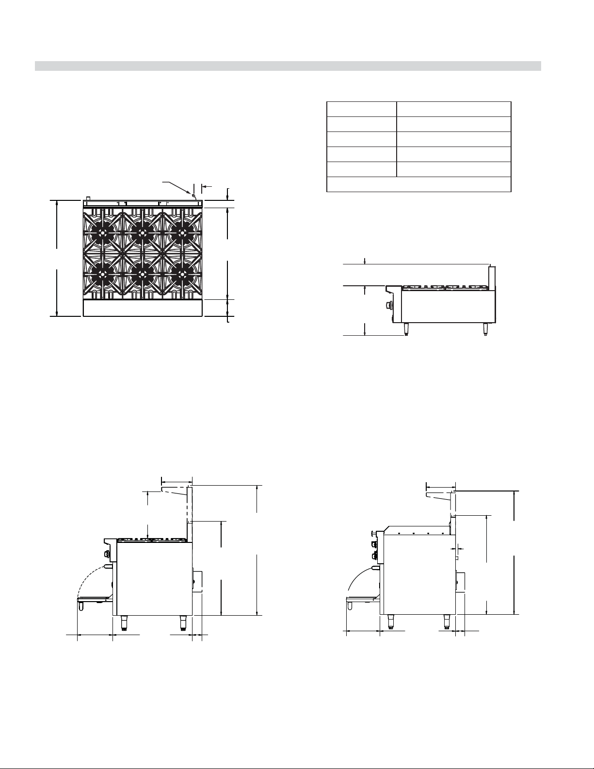
DIMENSIONS AND SPECIFICATIONS
Top View
Model widths vary depending on model series.
(See Chart on left)
ELECTRICAL PLUG
(WHERE APPICALBE)
3-1/2"
[89mm]
27-1/4"
[692mm]34-1/2"
[876mm]
2-1/4"
[57mm]
5"
[127mm]
Series Width
GF24 600mm (23-5/8”)*
GF36 900mm (35-2/2”)* Shown
GF48 1200mm (47-1/4”)
GF60 1500mm (59-1/2”)
*Range base or modular top
Modular Top Models GF24-_T or GF36-_T Side View
9-3/8" [238mm]
15-5/8"
[396mm]
GF Series Side View
(Showing convection base where applicable).
12-1/8"
[307mm]
18-3/8"
[466mm]
39-3/8"
[1000mm]
LOW PROFILE
BACKGUARD
13-7/8"
[352mm]
ADD WHEN
DOOR OPEN
31-1/8"
[791mm]
3-7/8" [98mm]
CONVECTION OVEN
[1290mm]
STD BACKGUARD
W/HIGH SHELF
(OPTIONAL)
ADD FOR
51"
GF Series 60” Raised Griddle/Broiler Side View
12-1/8"
[307mm]
CLEARANCE FROM TOP OF GRIDDLE PLATE
TO OPTIONAL HIGH SHELF 14-3/4" [374mm]
CLEARANCE FROM TOP OF GRATE
TO OPTIONAL HIGH SHELF 18-3/8" [466mm]
1"
[25mm]
GAS
INLET
[1041mm]
LOW PROFILE
BACKGUARD
13-7/8"
[352mm]
ADD WHEN
DOOR OPEN
31-1/8"
[791mm]
3-7/8" [98mm]
CONVECTION OVEN
51"
[1296mm]
STD BACKGUARD
W/HIGH SHELF
41"
ADD FOR
Part # 4525587 Rev 4 (29 April 14)Page 4
Page 5

DIMENSIONS AND SPECIFICATIONS continued
Base Model Designations & Total Input Rates
Input
Natural Gas Propane Gas
Model #* Description
BTU/Hr
GF/GFE24-4L 24” (600mm) nominal size unit, 4 open burners, space saver oven 136,000 41.50 132,000 39.70
GF24-T 24” (600mm) nominal size unit, 4 open burners, modular top 104,000 30.40 104,000 30.40
GF/GFE36-6R 36” (900mm) nominal size unit, 6 open burners, standard oven 194,000 56.70 188,000 54.90
GFE36-6C 36” (900mm) nominal size unit, 6 open burners, convection oven 194,000 56.70 188,000 54.90
GF36-T 36” (900mm) nominal size unit, 6 open burners, modular top 156,000 45.60 156.000 45.60
GF/GFE36-TTR
GFE36-TTC
GF/GFE48-LL
GF/GFE60-10RR
GFE60-10RC
GFE60-10CC
GF/GFE60-6R24RR
GFE60-6R24RC
GFE60-6R24CC
GF/GFE60-6R24RS
GFE60-6R24CS
*Models beginning with GFE pre x have electric spark ignition systems for pilots.
Rates are for installations up to 2000’ (610m) above sea level
Each 12”(305mm) Hot Top section is 5.3kW, replacing 2 Open Burners (7.6kW each)
36” (900mm) nominal size unit, 2 Front- red Target Hot Top
sections, standard oven
36” (900mm) nominal size unit, 2 Front- red Target Hot Top
sections, convection oven
48” (1200mm) nominal size unit, 8 open burners,
2 space saver ovens
60” (1500mm) nominal size unit, 10 open burners,
2 standard ovens
60” (1500mm) nominal size unit, 10 open burners, 1 standard &
1 convection oven
60” (1500mm) nominal size unit, 10 open burners,
2 convection ovens
60” (1500mm) nominal size unit, 6 open burner, 24” (610mm),
raised griddle/broiler, 2 standard ovens
60” (1500mm) nominal size unit, 6 open burner, 24” (610mm),
raised griddle/broiler, 1 standard & 1 convection oven
60” (1500mm) nominal size unit, 6 open burner, 24” (610mm),
raised griddle/broiler, 2 convection ovens
60” (1500mm) nominal size unit, 6 open burner, 24” (610mm),
raised griddle/broiler, 1 standard oven & 1 storage section
60” (1500mm) nominal size unit, 6 open burner, 24” (610mm),
raised griddle/broiler, 1 convection oven & 1 storage section
100,000 29.10 94,000 25.50
100,000 29.10 94,000 25.50
272,000 79.60 264,000 77.20
336,000 98.20 324,000 94.60
336,000 98.20 324,000 94.60
336,000 98.20 324,000 94.60
265,000 76.80 253,000 73.20
265,000 76.80 253,000 73.20
265,000 76.80 253,000 73.20
227,000 65.70 221,000 63.90
227,000 65.70 221,000 63.90
CE
Rating kWBTU/Hr
CE
Rating
kW
Clearances
Clearances Applicable For All Models Except Where Noted
Surface Sides Range Sides Modular Top Rear
Combustible Wall Minimum 14” (356mm) 6” (152mm) 6” (152mm)
Non-Combustible Wall Minimum 0” 0” 0”
Part # 4525587 Rev 4 (29 April 14) Page 5
Page 6
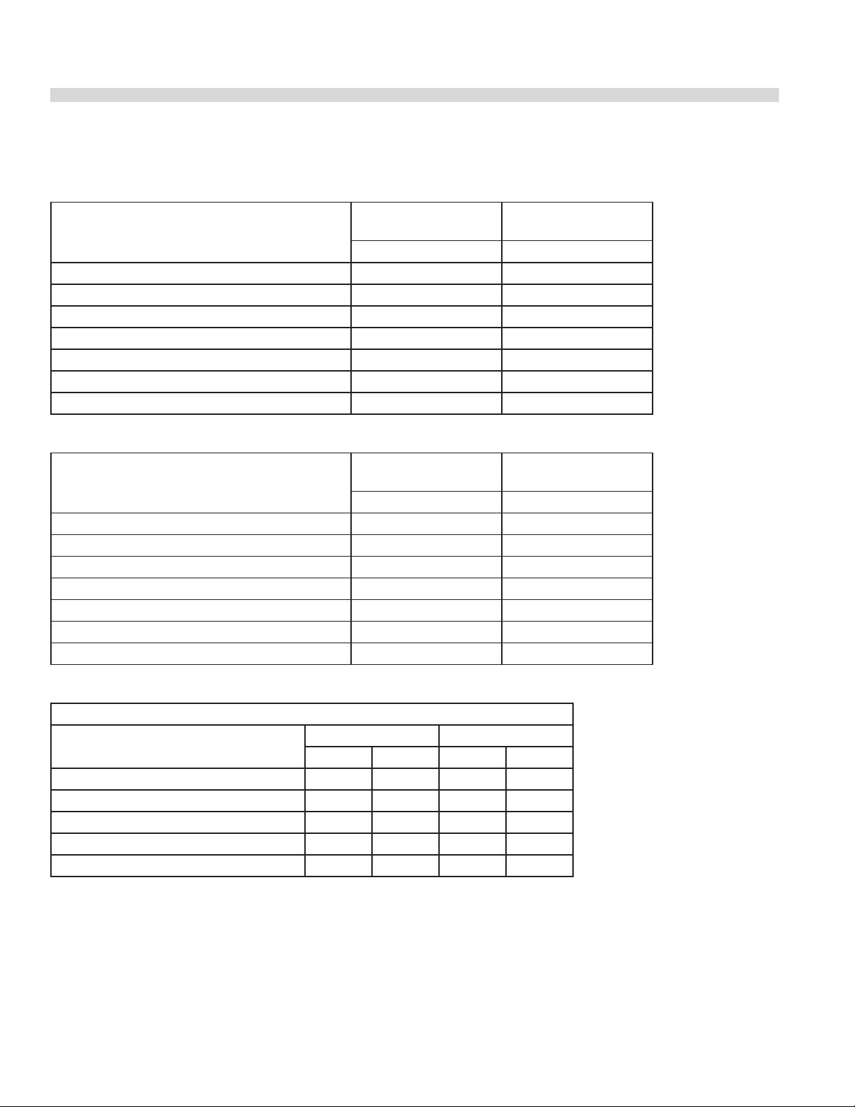
DIMENSIONS AND SPECIFICATIONS continued
Gas Pressure & Individual Burner Input Rates
North America
Nat.,
Garland GF Series
Open Top (Flame Failure) 26,000 26,000
Target Top 36” models only, per section 3@10,333 3@10,333
Hot Top FF (in lieu of 2 Open Top Burners) 18,000 18,000
Griddle (in lieu of 2 Open Top Burners)(Tstat) 18,000 18,000
Raised Griddle Broiler (3 burners) 3 @11,000 3 @11,000
26” Oven Burner (H-Cast)(Standard or Convection) 38,000 32,000
Space Saver Oven (H-Cast) 32,000 28,000
4.5” wc Manifold
BTU/h BTU/h
LPG,
10” wc Manifold
CE & General Export
Nat. (G20),
Garland GF Series
Open Top (Flame Failure) 7.6 7.6
Hot Top FF (in lieu of 2 Open Top Burners) 5.3 5.0
Target Top “36” models, only per section 3@3.0 3@2.7
Griddle (in lieu of 2 Open Top Burners)(Tstat) 5.3 5.3
Raised Griddle Broiler (3 burners) 3 @ 3.0 3 @ 3.0
26” Oven Burner (H-Cast)(Standard or Convection) 11.1 9.3
Space Saver Oven (H-Cast) 9.4 8.2
11.2 mbar Manifold
kW kW
LPG (G31),
24.9 mbar Manifold
Reduced Input Rates
Approximate input ratings for adjustable top burners set at LOW:
Garland GF Series
Open Top Burner (Flame Failure) 2.0 0.21 4.2 0.17
Hot Top (Flame Failure) 2.75 0.29 4.9 0.20
Griddle (Tstat) 3.0 0.32 2.0 0.08
Raised Griddle Broiler (Total Of 3 Burners) 3.0 0.32 5.9 0.24
Target Top 2.7 0.28 4.0 0.16
NAT(G20) LPG(G31)
kW m
3
/h kW m3/h
Note: Manifold pressure is to measured at the test spigot located on the /” gas manifold pipe.
Part # 4525587 Rev 4 (29 April 14)Page 6
Page 7

DIMENSIONS AND SPECIFICATIONS continued
Australia
Garland GF Series
Nat., 1.0kPa Manifold LPG, 2.49 kPa Manifold
MJ/H Injector MJ/H Injector
Open Top (Flame Failure) 30.6 37 (2.64mm) 28.49 53 (1.51mm)
Hot Top FF (in lieu of 2 Open Top Burners) 19.0 47 (1.99mm) 18.15 1.2mm
Front Fired Hot Top (Target Top) 36.5 52(1.61mm) 36.5 1.0mm
Griddle (in lieu of 2 Open Top Burners)(Tstat) 19.0 47 (1.99mm) 18.15 1.2mm
Raised Griddle Broiler (3 burners) 30.0 47 (1.99mm) 34.82 61 (0.99 mm)
26” Oven Burner (H-Cast)(Standard) 40.09 30 (3.26mm) 33.76 50 (1.78mm)
26” Oven Burner (H-Cast) (Convection) 40.09 30 (3.26mm) 32.18 51 (1.7mm)
Space Saver Oven (H-Cast) 33.7 33 (2.87mm) 27.96 52 (1.61mm)
Gas Inlet Size
Model Width Connection
23-5/8” (600mm) &
35-1/2” (900mm)
47-1/4” (1200mm) &
59-1/2” (1500mm)
3/4” NPT
Rear Gas Connection
1” NPT
Rear Gas Connection
Connection CE Models
(ISO7-1)
3/4” (19.1mm) BSPT
1” (25.4 mm) BSPT
CE Approved Gas Categories
Country Gas Category Gas Type Pressure (mbar)
AT, CH, CY, CZ, DK, EE, ES, FI, GB, GR, HR, IE, IT,
LT, LV, NO, PT, RO, SE, SI, SK, TR
BE, CH, CZ, ES, FR, GB, GR, HR, IE, IT, LU, PL, PT I
AT, BE, CH, CZ, DE, ES, FR, GB, HU, NL I
CH, CZ, ES, GB, GR, HR, IE, IT, PT II
CH, CZ, ES, GB, II
I
2H
3P
3P
2H3P
2H3P
G20 20
G31 37
G31 50
G20 20
G31 37
G20 20
G31 50
Part # 4525587 Rev 4 (29 April 14) Page 7
Page 8

INTRODUCTION
1. Check crate for possible damage sustained during transit.
Carefully remove unit from crate and again check for
damage. Any damage to the appliance must be reported
to the carrier immediately.
2. The wires for retaining packing material must be
removed from units. Any protective material covering
stainless steel parts must also be removed.
3. All equipment is supplied with 6” (152mm) legs unless
speci ed to be dais for cove base mounting, casters
or deck mount anged feet. Units 48” (1200mm) and
60” (1500mm) wide have legs factory mounted. Base
mounting is required when range is being installed on a
combustible oor.
4. The type of gas and supply pressure that the equipment
was set-up for at the factory is noted on the rating plate
and on the packaging. This type of gas supply must be
used.
5. Do not remove permanently a xed labels, warnings or
rating plates from the appliance, for this may invalidate
the manufacturer’s warranty.
Rating Plate
All burner input rates are shown on the rating plate, which is
located behind the lower front drop down panel under the
oven door.
Safety Information
Warning: Accessible parts may become hot during use.
Young children should be kept away.
This appliance is for professional use and should only be
used by quali ed personnel
This appliance is not intended for use by persons (including
children) with reduced physical, sensory or mental
capabilities, or lack of experience and knowledge, unless
they have been given supervision or instruction concerning
use of the appliance by a person responsible for their safety.
Part # 4525587 Rev 4 (29 April 14)Page 8
Page 9
INSTALLATION
This product has been certi ed as commercial cooking
equipment and must be installed by professional personnel
as speci ed. THIS APPLIANCE IS NOT RECOMMENDED FOR
RESIDENTIAL INSTALLATION.
Garland suggest installation, maintenance and repairs
should be performed by your local Garland/US Range
authorized service agency, when ever possible.
Siting
The oor on which the appliance is to be sited must
be capable of adequately supporting the weight of
the appliance and any ancillary equipment. Units with
ovens must be tted with legs or casters if installed on a
combustible oor. Adequate clearance must be provided for
servicing and proper operation.
Appliances Equipped With Casters
1. The installation shall be made with a connector that
complies with the Standard for Connectors for Moveable
Gas Appliances, ANSI Z21.69/CSA 6.16, Addenda
Z21.69B-2006/CSA 6.16B-2006 (or latest edition), and a
quick-disconnect device that complies with the Standard
for Quick Disconnects for Use with Gas Fuel, ANSI Z21.41/
CSA 6.9, Addenda Z21.41A-2005/CSA 6.16A-2005
(or latest edition).
2. The front casters of the appliance are equipped with
brakes to limit the movement of the appliance without
placing any strain on the connector or quick disconnect
device or its associated piping.
3. Please be aware that required restraint is attached to a
cut out hole in side panel, and if disconnection of the
restraint is necessary, be sure to reconnect the device
after the appliance has been returned to its original
position.
Appliances Equipped With Legs
1. Raise the front of the appliance and block. Do not lay the
appliance on its back.
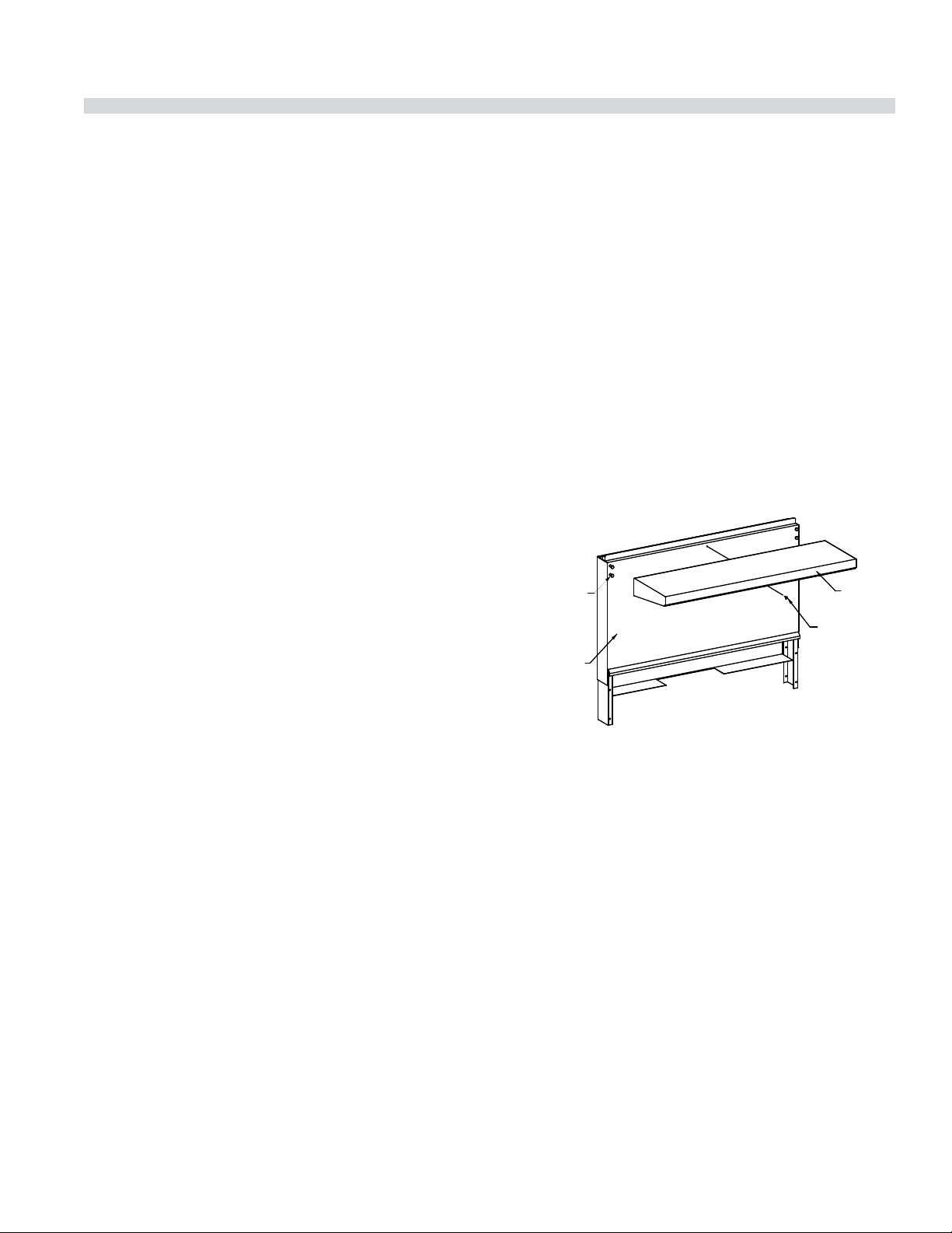
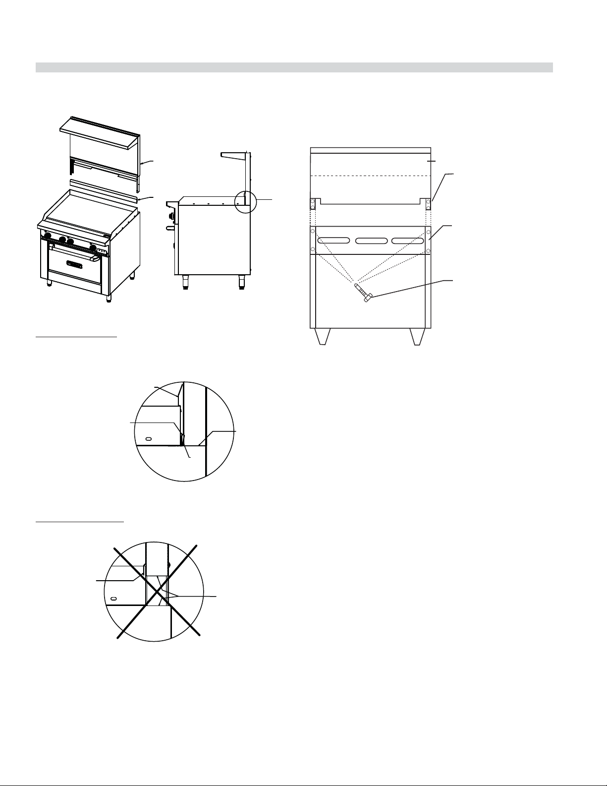
Installing Shelf To Backguard
Note: Shelf may be installed before or after installing the
backguard to the range.
1. Loosen 4 bolts on the front of the backguard
approximately 1/4” (6mm).
2. Align the 4 slotted holes on the back of the shelf with the
4 bolts on the backguard.
3. Slide the shelf downward until the 4 bolts are engaged in
the slotted portion of the keyhole.
4. Tighten the 4 bolts to secure the shelf.
5. On 60” units only, install a sheet metal screw though the
hole in the underside of the shelf into the backguard and
tighten.
MOUNTING
BOLTS
BACKGUARD
SHELF
SHEETMETAL
SCREW
Backguard With High Shelf Or Salamander
Mounting Instructions
1. Rear of the range must be easily accessible.
2. Please refer to the installation instructions included with
the salamander for further instructions on these units.
3. Place the backguard or high shelf on the rear of the
range, slipping the support brackets into the openings in
the main body sides.
2. Legs are threaded to be easily screwed into the holes
provided on the bottom of the range.
3. Once legs have been attached and secured they can
be adjusted to level the appliance and compensate for
uneven ooring.
Part # 4525587 Rev 4 (29 April 14) Page 9
4. For ranges with griddles, care must be taken when
mounting the backguard or high shelf. The front panel
of the stainless steel backguard or high shelf has an
extruding lip at the bottom. This lip must NOT go over
the griddle back splash, if it does the backguard will not
t properly and the range will not ue properly. Refer to
illustration for proper installation.
Page 10
INSTALLATION Continued
BACKGUARD
5. Securely fasten the support brackets to the burner box
sides with (4sheet metal screws provided).
SPLASH
GUARD
Correct Installation
CLIP GRIDDLE SPLASH GUARD
ONTO BACK FLANGE OF GRIDDLE
(SHIPPED ON TOP OF GRIDDLE)
BACKGUARD LIP GOES
BEHIND BACK FLANGE
OF GRIDDLE & OVER
ANGLE FLANGE
Incorrect Installation
BACKGUARD
LIP ON BACK
FLANGE
OF GRIDDLE
ANGLE
FLANGE
FLUSH WITH
SIDE PANEL
NOT FLUSH
WITH
SIDE PANEL
DETAIL
AREA
Upright
Main Body
Side
Sheet Metal
Screws (4 Req'd)
Ventilation Air
The following notes are intended to give general guidance.
For detailed recommendations, refer to the applicable
code(s) in the country of destination. These appliances shall
be installed in a room with su cient ventilation to prevent
the occurrence of hazardous concentrations of combustion
by-products.
The room containing the appliance is required to have a
permanent vent. The minimum e ective area of the vent is
related to the maximum rated heat input of the appliance
and shall be 4.5 cm2 per kW in excess of 7 kW.
Proper ventilation is critical for optimum performance. The
ideal method of ventilating open-top equipment is the use
of a properly designed canopy that should extend six inches
(152 mm), beyond all sides of the appliance(s) and six feet, six
inches (1981mm) above the oor.
Air vents should be of such a size as to compensate for the
e ects of any extract fan in the premises. A strong exhaust
will create a vacuum in the room. For an exhaust vent to work
properly, replacement air must be equal to the amount of air
exhausted. An imbalance between exhaust and replacement
air can cause degradation in the appliance’s performance.
All gas burners and pilots need su cient air to operate. Large
objects should not be placed in front of the appliance(s) that
would obstruct the ow of air into the front.
Part # 4525587 Rev 4 (29 April 14)Page 10
Page 11

INSTALLATION Continued
Statutory Regulations
In European countries, installation must be carried out by
a competent person and in accordance with the relevant
regulations, codes of practice and the related publications of
the country of destination.
In the United States, the installation must conform to the
National Fuel Gas Code ANSI Z223.1, or latest edition, NFPA
No.54 - latest edition/or local code to assure safe and e cient
operation. In Canada, the installation must comply with CSA
B149.1 and local codes.
Australia Speci c Clause
This appliance must be installed in accordance with the
manufacturer’s instructions, local gas tting regulations
and requirements of AS 5601 installation code. All burner
adjustments and setting should be made by a quali ed gas
technician.
Electrical Connection Settings
(Where Applicable)
IMPORTANT- This appliance must be electrically grounded in
accordance with local codes, or in the absence of local codes
with the National Electrical Code.
220/240 Volt Convection Oven Models
When the appliance is ordered and equipped for 220/240
volt operation, the supply line must be connected to the
wiring terminations located inside the terminal box at the
rear of the appliance.
For ease of attaching the supply line, there is a removable
cover on the terminal box.
Permanent connection to the electrical service must comply
with local codes, or in the absence of local codes, with the
national electrical code.
All xed (non-mobile) appliances MUST be tted with an
accessible upstream gas shut o valve as a means of isolating
the appliance for emergency shut o and for servicing. A
union or similar means of disconnection must be provided
between the gas-cock and the appliance.
A manually operable valve must be tted to the gas supply
to the kitchen to enable it to be isolated in an emergency.
Wherever practical, this shall be located either outside the
kitchen or near to an exit in a readily accessible position.
Where it is not practical to do this, an automatic isolation
valve system shall be tted which can be operated from a
readily accessible position near to the exit.
In locations where the manual isolation valve is tted or the
automatic system can be reset this notice MUST be posted:
“ALL DOWNSTREAM BURNER AND PILOT VALVES MUST
BE TURNED OFF PRIOR TO ATTEMPTING TO RESTORE THE
SUPPLY. AFTER EXTENDED SHUT OFF, PURGE BEFORE
RESTORING GAS.”
Installation Notes
Before assembly and connection, check gas supply.
A. The type of gas for which the unit is equipped is stamped
on the rating plate located behind the lower front
panel. Connect a unit stamped “NAT” only to natural gas;
connect one stamped “PRO” only to propane gas.
B. If it is a new installation have the gas authorities check
meter size and piping to assure that the unit is supplied
with the necessary amount of gas pressure required to
operate the unit.
C. If it is additional or replacement equipment have the gas
authorities check pressure to make certain that existing
meter and piping will supply fuel to the unit with no
more than 0.15 Kpa pressure drop.
Gas Connection
The local gas authority should be consulted at the
installation planning stage in order to establish the
availability of an adequate supply of gas and to ensure
that the meter is adequate for the required ow rate. The
pipe work from the meter to the appliance must be an
appropriate size.
Part # 4525587 Rev 4 (29 April 14) Page 11
D. Make certain new piping and connections have been
made in a clean manner and have been purged so that
piping compound, chips, etc. will not clog pilots, valves or
burners. Use pipe joint compound approved for natural
and lique ed petroleum gases.
NOTE: Gas pressure should be checked when the unit is
installed with all other equipment on the same line turned
on. The operating manifold gas pressure must be the same
as that speci ed on the rating plate. If necessary, pressure
adjustment may be made at the pressure regulator supplied
with the appliance.
Page 12
INSTALLATION Continued
The appliance pressure regulator provided by the factory
is pre-set to the correct manifold pressure. The manifold
pressure may require veri cation and adjustment at the
installation. Allow at least one burner to be ignited and
operating while checking manifold pressure at the test
spigot located on the appliance manifold, and adjust the
appliance pressure regulator accordingly.
The appliance and its individual shut-o valve must be
disconnected from the gas supply piping system during any
pressure testing of that system where pressures are in excess
of 1/2 PSIG (3.45kPa.)
5
TO INLET OF SALAMANDER/
8
CHEESEMELTER MANIFOLD
REGULATOR - 6.0"w.c. NATURAL GAS
OR 10.0"w.c. PROPANE GAS
(SUPPLIED WITH SALAMANDER/
CHEESEMELTER)
Final Preparation
NOTE: Your new range has a plastic coating to help protect
the nish from scratches during shipping. This protective
plastic lm should be peeled o prior to starting the range.
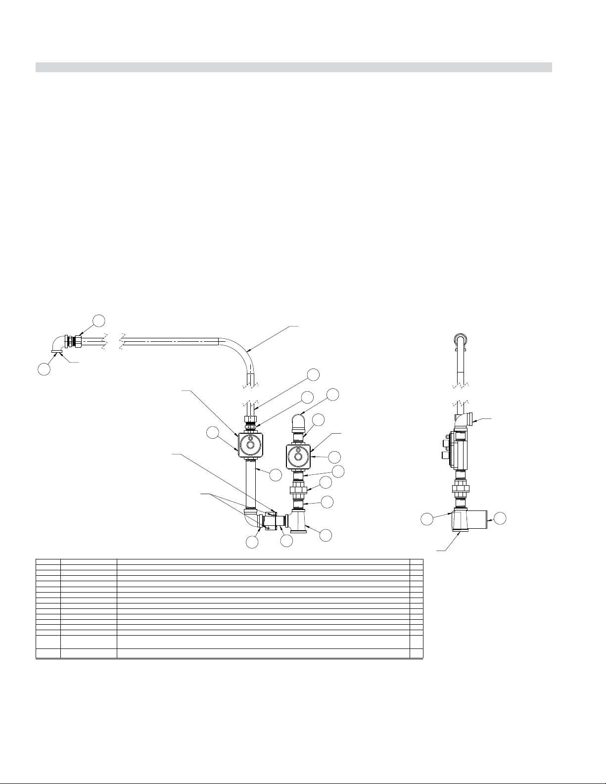
Optional Interconnect Gas Kit
To interconnect range mount salamanders with range
The GF series Garland range can be equipped with a range
mount gas salamander. Salamanders can be plumbed
independently or be interconnected with the range. See
Drawing for various options for mounting onto a 36”
(900mm) a 48” (1200mm) or a 60” (1500mm) range.
CUT TUBING (ITEM 15 - 4531608) TO SIZE AS REQUIRED
TO SUIT SALAMANDER/CHEESEMELTER TOP OR REAR
MANIFOLD INLET CONNECTION
15
SUPPLIED WITH RANGE
3
5
15 4531608
14
13
2127503/2127500
12
11
10
9
8
7
6 2640700
5 3013000
4
3
2
NAT: 2127502/4525047
1
PRO: 2127500/4525048
ITEM NO.
PART NUMBER
ATTACH SUPPORT CLAMP (ITEM 7 - 2640800)
TO SUPPORT BRACKET ( ITEM 6 - 2640700)
WITH (2)#10-24 SELF-TAPPING SCREWS (ITEM 12
F32 - NOT SHOWN) PROVIDED.
MARK HOLE LOCATIONS AND MOUNT
SUPPORT BRACKET (ITEM 6 - 2640700) TO RANGE
BACK WITH (2)#10-16 TEKS SELF-DRILL/TAP
SCREWS (ITEM 11 - F67 - NOT SHOWN) PROVIDED.
G01738-11
F32
F67
G03716-1
G01738-5
G01474-9
2640800
G01963-1
G01474-5
G01738-14
6.0"wc 3/4"NPT REG. NATURAL GAS/10"wc 3/4" NPT REG. PROPANE GAS - SUPPLIED WITH SALAMANDER/CHEESEMELTER
4.5"wc 3/4"NPT/3/4" ISO 7-1 REG. NATURAL GAS OR 10"wc 3/4"NPT/3/4" ISO 7-1 REG. PROPANE GAS - SUPPLIED W/RANGE
SUPPLIED WITH RANGE
2
13
9
3
3/4" X 51" X 33" TUBING
3/4" NPT X 3.5" PIPE NIPPLE
SCREW-10-24X1/2" PAN HD SELF-TAP TYPE F (NOT SHOWN)
SCREW - #10-16 X 1/2" HEX WASHER HEAD TEKS SELF DRILL/TAP (NOT SHOWN)
3/4" NPT X 3/4" NPT X 1" NPT REDUCING TEE
3/4" NPT X 6.5" PIPE NIPPLE
3/4" NPT X 1/2" NPT 90 DEG. REDUCING ELBOW
PIPE SUPPORT BRACKET CLAMP
PIPE SUPPORT BRACKET
3/4" CC X 3/4" NPT STRAIGHT FITTING
90 DEGREE ELBOW 3/4" NPT (ONE SUPPLIED WITH RANGE)
3/4" NPT X 2IN PIPE NIPPLE (ONE SUPPLIED WITH RANGE)
3/4" NPT PIPE UNION
DESCRIPTION
14
REGULATOR - 4.5" w.c. NATURAL GAS
OR 10.0" w.c. PROPANE GAS
(SUPPLIED WITH RANGE)
1
2
4
2
10
7
1" NPT GAS SUPPLY
CONNECTION
1
1
1
2
2
1
1
1
1
1
2
1
2
3
1
QTY
TO INLET OF RANGE
MANIFOLD
6
Optional Interconnect Gas Kit
36in (900mm) G/U/X
Part # 4531606
Part # 4525587 Rev 4 (29 April 14)Page 12
Page 13
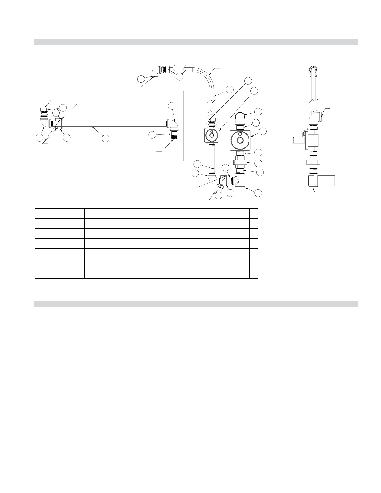
INSTALLATION Continued
TO INLET OF SALAMANDER/
CHEESEMELTER MANIFOLD
FOR LEFT-MOUNTED SALAMANDER/CHEESEMELTER
SUBSTITUTE COMPONENTS SHOWN FOR ITEM 17 CIRCLED IN ADJACENT VIEW
6
TO INTER-CONNECT TUBING ( ITEM 18 - 4531608)
17
10
MARK HOLE LOCATIONS AND MOUNT
SUPPORT BRACKET (ITEM 9 - 4531602 ) TO RANGE
BACK WITH (2) #10-16 TEKS SELF-DRILL/TAP
SCREWS (ITEM 14 - F67 - NOT SHOWN) PROVIDED.
ATTACH SUPPORT CLAMP (ITEM 10 - 2640800)
TO SUPPORT BRACKET (ITEM 9 - 4531602)
WITH (2) #10-24 SELF-TAPPING SCREWS (ITEM 1
F32 - NOT SHOWN) PROVIDED
9
12
TO OUTLET OF SALAMANDER/
CHEESEMELTER REGULATOR
16
13
NOTE: CUT TUBING (ITEM 18 - 4531608) TO SIZE AS REQUIRED
TO SUIT SALAMANDER/CHEESEMELTER TOP OR REAR
17
6
MANIFOLD INLET CONNECTION
17
18
3
REGULATOR - 6.0"w.c.
NATURAL GAS OR 10.0"w.c.
PROPANE GAS (SUPPLIED
WITH SALAMANDER/CHEESEMELTER)
SUPPLIED WITH
7
RANGE
SUPPLIED WITH
4
RANGE
2
REGULATOR - 4.5"w.c.
NATURAL GAS OR 10.0"w.c.
PROPANE GAS (SUPPLIED
WITH RANGE)
4
TO INLET OF RANGE
MANIFOLD
ATTACH SUPPORT CLAMP (ITEM 10 - 2640800)
TO SUPPORT BRACKET (ITEM 9 - 4531602)
WITH (2) #10-24 SELF-TAPPING SCREWS (ITEM 1
F32 - NOT SHOWN) PROVIDED
MARK HOLE LOCATIONS AND MOUNT
SUPPORT BRACKET (ITEM 9 - 4531602) TO
BACK WITH (2) #10-16 TEKS SELF-DRILL/TAP
SCREWS (ITEM 14 - F67 - NOT SHOWN) PROVIDED.
18 4531608
17 3013000
16
15
14
13
12
11 3012800
10 2640800
9 4531602
8 4530189
7
6
5
4
3
NAT: 4522421/4525049
2
PRO: 4522422/4525050
1
ITEM NO.
G01474-9
G01738-11
F67
G01738-14
G01738-16
076029-171
G01474-5
G01738-5
076029-204
2127503/2127500
F32
PART NUMBER
SCREW - #10-16 X 1/2" HEX WASHER HEAD TEKS SELF-DRILL/TAP (NOT SHOWN)
4.5"wc 3/4"NPT REG. NATURAL GAS/10"wc 3/4"NPT REG. PROPANE GAS - PROVIDED WITH SALAMANDER/CHEESEMELTER
4.5" wc 1" NPT/ 1" ISO 7-1 REG. NATURAL GAS OR 10"wc 1"NPT/1" ISO 7-1 REG. PROPANE GAS - PROVIDED WITH RANGE
SCREW - #10-24 X 1/2" PAN HD SELF-TAP TYPE F (NOT SHOWN)
3/4" X 51" X 33" TUBING
3/4" CC X 3/4" NPT STRAIGHT FITTING
3/4" NPT X 1/2" NPT 90 DEG. REDUCING ELBOW
3/4" NPT X 3.5" PIPE NIPPLE
3/4" NPT X 2.000 PIPE NIPPLE
3/4" NPT X 22.750 PIPE NIPPLE
1" NPT X1" NPT X 3/4" NPT REDUCING TEE
PIPE SUPPORT BRACKET CLAMP
PIPE SUPPORT BRACKET 48/60
1" NPT 90 DEGREE ELBOW(SUPPLIED WITH RANGE)
1" NPT X 2" PIPE NIPPLE (ONE SUPPLIED WITH RANGE)
1" NPT PIPE UNION
90 DEGREE ELBOW 3/4" NPT
3/4" NPT X 6.5" PIPE NIPPLE
DESCRIPTION
TESTING AND ADJUSTMENT
Testing
All ttings and pipe connections must be tested for
leaks. Use approved gas leak detectors, soap solution or
equivalent, checking over and around all the ttings and
pipe connections. DO NOT USE A FLAME! Accessibility to
all gas lines and ttings require that valve panel(s) lower
front panel(s), and/or oven rack(s) be removed. It may be
necessary to remove, or at least raise and securely prop
griddle(s), hot top(s), and/or top grate(s). All parts removed,
(including fasteners), should be stored safely for reinstallation.
1. Be sure that all valves and thermostats are in the “OFF”
position.
5
6
15
10
9
8
4
11
1
2
1
1
4
1
1
1
2
QTY
2
1
1
3
1
3
1
1
4
Optional Interconnect Gas Kit
48in (1200mm) & 60in (1500mm) G/U/X
Part # 4531606
1" NPT GAS SUPPLY
CONNECTION
2. Turn on the main gas supply valve. Light all top section
pilots.
3. Leak test all valves and ttings as described at the
beginning of this section. Correct any leaks as required
and recheck.
4. Light the oven pilot.
5. Set the oven thermostat to maximum. Leak test all valves
and ttings as described at the beginning of this section.
Correct any leaks as required and recheck.
6. Shut o all valves and set thermostat dials to “OFF” or
lowest position. All units are tested and adjusted at the
factory, however, burners and pilots should be checked
upon installation and adjusted if necessary.
Part # 4525587 Rev 4 (29 April 14) Page 13
Page 14

OPERATION
Flame Failure Technology
The Garland GF series gas range has total ame failure (also
referred to as ame safety) technology. It is a simple system
that monitors the existence of a gas ame. It can be used on
most gas appliances and will turn o the gas supply to any
burner using the system when a pilot ignition ame is not
present.
Flame failure systems have been available for many years
and it is the “CE” agency standard accepted for European gas
appliance approvals. In North America this technology is
gaining greater acceptance and various levels of government
are making it mandatory in schools and other government
institutions.
How Flame Failure Technology Works
For gas restaurant ranges, there are three principles at
work in a ame failure system, they are a safety valve, the
thermocouple and the pilot.
Safety Valve
The SIT control used on the new Garland series of restaurant
ranges operates both as the mechanism to control the
oven temperature (thermostat) and the safety valve for the
ame failure system. This valve contains a magnet which
when electrically charged, will hold a check valve in an open
state allowing for gas to ow through the valve as required
by either the pilot or main burner. The magnet is charged
through an electrical signal sent from the thermocouple
when a ame is present. When no ame is present, no signal
is sent and the magnet releases closing the check valve.
Because no gas can ow through the valve if the pilot is not
burning, no gas can build up, decreasing the risks a of any
safety conditions.
magnet in the safety valve releases to close o the supply
gas.
Pilot
The pilot provides the ame that the thermocouple uses to
generate millivolts. When all three of the above components
are placed together a Flame Failure system is created.
The above principles apply no matter what section of the
range is using ame failure technology. When operating
open top burners or hot tops the hi-lo valve also acts as a
safety valve in the system. The same SIT thermostat as in the
oven section of the range is used on at griddle models.
Burner Operation
Caution: In the event that a binding or malfunctioning
valve, or thermostat control is observed DO NOT light the
pilots or continue operation until an authorized service
technician has inspected the appliance. Failure to do so
may result in injury.
Open Top burners
Lighting
1. Push in the valve knob, and turn it counter clockwise to
the ignition “” position.
2. While holding the valve knob fully in, light the pilot
burner with a match or BBQ ignition device.
Note: On ranges equipped with electric spark igniters, press
the igniter button and check that the pilot lights. Should
burner ignition fail within 4 seconds, turn the burner valve
o and repeat steps 1 through 2. If ignition continues to fail,
consult the factory authorized service agency.
Thermocouple
The thermocouple is positioned so that the tip of the
thermocouple comes into contact with the pilot ame
when lit. When exposed to a ame, a properly functioning
thermocouple produces a small electrical signal measured
in millivolts. This signal is transferred through the electrical
wire connecting the thermocouple to the safety valve in
the SIT control, and to the magnet inside the valve thereby
energizing it. Again, when the magnet is energized, it is able
to hold a check valve in an open state allowing gas to ow
through the valve to the burner(s) and pilot(s). If the pilot
goes out then the generation of millivolts stops and the
3. When the pilot is lit continue to hold the valve knob fully
in for at least 30 seconds, then release it. If the pilot goes
out, wait for (5), minutes, then repeat from step 1.
4. When the pilot remains lit, push the valve in again and
turn it counter-clockwise to the desired ame setting
position, lighting the burner.
Part # 4525587 Rev 4 (29 April 14)Page 14
Page 15
OPERATION Continued
Shut Down
1. To turn the burner o and still have the pilot remain on,
turn the dial to the ignition “ ” position.
2. To turn the burner and pilot o , turn the dial to the
circular “OFF” symbol. The safety device will disengage
within 60 seconds.
Hot Tops and Front-Fired Target Tops
Lighting
1. Push in the valve knob, and turn it counter clockwise to
the ignition “ ” position.
2. While holding the valve knob fully in, press the igniter
button and observe if the pilot lights. If it does not light,
repeatedly depress the igniter button until it does.
Note: On ranges equipped with electric spark igniters, press
the igniter button and check if the pilot lights. Should burner
ignition fail within 4 seconds, turn the burner valve o and
repeat steps 1 through 2. If ignition continues to fail, consult
the factory authorized service agency.
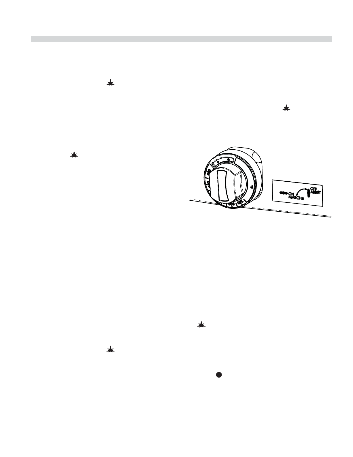
Ovens (Standard)
Lighting
1. Lower front kick panel below oven door, raise oven
hearth bottom for easy access to oven pilot.
2. Turn oven control knob ( gure 1) to “ ” position and
then push in to engage the ow of gas through the safety
device to the pilot.
Figure 1
3. When the pilot is lit continue to hold the valve knob fully
in for at least 30 seconds, then release it. If the pilot goes
out, wait for (5), minutes, then repeat from step 1.
4. When the pilot remains lit, push the valve in again and
turn it counter-clockwise to the desired ame setting
position, lighting the burner.
5. For low ame or simmer push in the valve knob and turn
it counter-clockwise to the low ame position.
6. Surface plates are capable of reaching very high
temperatures, solid hot tops 380C(716F) front - red
target tops 585C(1085F).
Shut Down
1. To turn the burner o and still have the pilot remain on,
turn the dial to the ignition “ ” position.
2. To turn the burner and pilot o , turn the dial to the
circular “OFF” symbol. The safety device will disengage
within 60 seconds.
3. While holding knob in, light pilot with a match/BBQ
lighter or use the spark ignition (if provided) to spark
ignite pilot.
4. Continue to hold knob in for 15 seconds after ignition,
then release. Pilot should remain lit.
5. If pilot burner fails to light or does not stay lit, wait 5
minutes and repeat steps 2 through 4.
6. Replace hearth or close kick panel, then turn oven
thermostat to desired cooking temperature.
7. To shut down main burner turn control knob ( gure 1) to
“ ” position.
Warning: Use caution when opening the oven door while it
is in use. Hot air or steam may cause injury.
Shut Down
If pilot shut down is required push in oven thermostat knob
and turn to “ ” symbol. The system will disengage with in 60
seconds.
Part # 4525587 Rev 4 (29 April 14) Page 15
Page 16

OPERATION Continued
Convection Ovens
The forced air range oven consists of a food preparation
chamber completely sealed from the combustion area.
This eliminates the possibility of contamination from ue
products and permits an e cient method of circulating the
heated air within the cooking chamber.
During the cooking process in a conventional oven, a vapor
barrier and a layer of “cool” air covers the exposed area of
the product. In a forced air oven, the fan pushes the heated
air over and around the product, sweeping away the vapor
barrier and cool air, permitting faster heat penetration. This
action permits the use of lower temperatures and shorter
cooking times.
The rule of thumb for determining the cooking temperature
is to reduce the set temperature by approximately
80°F, (28°C), from that which you would set in a conventional
oven. The product should be checked at a point midway in
the time required in a conventional oven.
Lighting
1. Lower front kick panel below oven door.
Cool down
1. Turn the oven valve knob to the “ ” position this will
prevent the main oven burner from cycling on. ( gure 1).
2. Turn the thermostat to its lowest setting.
3. Open the oven door.
Warning: Use caution when opening the oven door while it
is in use. Hot air or steam may cause injury.
4. Set the power switch to the “COOL DOWN” position.
5. Once the oven has cooled turn the power switch to o
and close the oven door.
Shut Down
1. If pilot shut down is required push in oven thermostat
knob turn to “ ” symbol. The system will disengage with
in 60 seconds.
2. Power switch should be in the o position.
Operating Suggestions
2. Push and hold in oven thermostat control valve knob
( gure 1) and turn it counter clockwise to the ignition
position “ ”.
3. While holding knob fully in depress the red igniter button
and observe that the pilot ame is lit. If it does not light,
repeatedly depress the igniter button until it does.
Note: On ranges equipped with electric spark igniters, press
the igniter button and check if the pilot lights. Should burner
ignition fail within 4 seconds, turn the burner valve o and
repeat steps 1 through 2. If ignition continues to fail, consult
the factory authorized service agency.
4. When the pilot is lit, continue to hold the valve knob fully
in for 15 seconds, then release it. If the pilot goes out, wait
for ve (5) minutes, then repeat steps 2 to 4.
Start Up
1. Set the power switch to the “COOK” position.
2. Turn the thermostat to the desired setting.
The motor in your range convection oven is maintenance
free since it is constructed with self-lubricating sealed ball
bearings. It is designed to provide durable service when
treated with ordinary care. We have a few suggestions to
follow for the care of your motor.
A. When the motor is operating, it cools itself internally by
air entering the rear of the motor case, provided proper
clearance has been allowed.
B. Since the blower wheel is in the oven cavity it is at the
same temperature as the oven. If the motor is stopped
while the oven is hot, the heat from the blower wheel is
conducted down the shaft and into the armature of the
motor. This action could shorten motor life.
C. We recommend, at the end of the bake or roasting
period, when the oven will be idle for any period of time
or before shutting down completely, that the doors
be left open, and by use of the cool-down position on
the fan switch, the fan continues to run for at least 20
minutes. The “FAN” should never be turned “OFF” when
the oven section is in use.
Part # 4525587 Rev 4 (29 April 14)Page 16
Page 17
OPERATION Continued
D. All convection oven model units have a controllable
moisture vent. The vent control is a sliding cover inside
the oven cavity. Sliding the vent from left to right will
increase or decrease the amount moisture inside the
oven during cooking. Dryness or moisture of the nished
product will dictate the setting of the vent. To speed up
pre-heat time close the vent during preheat.
Thermostat Controlled Griddles
See griddle seasoning before use.
1. For general thermostat griddle lighting instructions
please refer to the section entitled “OVEN (STANDARD)”
above. (Steps 2 though 7)
2. Pilots should be lit though the front panel with an extend
match or long BBQ lighter. If necessary the front panel of
the range can be removed to allow the griddle plates to
be raised at the front, block securely.
3. Light pilots located at the front left side of each burner
4. The sensing bulbs must be fully inserted into their
individual holders, which are located on the underside
of the griddle. To check griddle burner ame set the
thermostat to its maximum setting and then return to
pilot.
5. If the griddle has been raised to light the pilots, lower
carefully into position, being very careful not to leave any
part of the capillary tube in the burner compartment.
Replace the front panel of the range.
6. Surface temperature of solid griddle top is capable of
reaching at least 265C (509 F).
Griddle/Broiler
See griddle seasoning before use.
Lighting
1 Push in the valve knob, and turn it counter clockwise to
the ignition “ ” position.
2 While holding the valve knob fully in, press the igniter
button and check if the pilot lights. If it does not,
repeatedly depress the igniter button until it does.
Note: On ranges equipped with electric spark igniters, press
the igniter button and check that the pilot lights. Should
burner ignition fail within 4 seconds, turn the burner valve
o and repeat steps 1 through 2. If ignition continues to fail,
consult the factory authorized service agency.
3. When the pilot is lit continue to hold the valve knob fully
in for at least 30 seconds, then release it. If the pilot goes
out, wait for (5), minutes, then repeat from step 1.
4. When the pilot remains lit, push the valve in again and
turn it counter-clockwise to the desired ame setting
position, lighting the burner.
5. For low ame or simmer push in the valve knob and turn
it counter-clockwise to the low ame position.
6. Surface Temperature of solid griddle top is capable of
reaching at least 380C (716 F).
Shut Down
1. To turn the burner o and still have the pilot remain on,
turn the dial to the ignition “ ” position.
Caution: Only authorized service
technicians should be removing thermostat
control knobs. In the event the thermostat
temperature knob has been removed, the set
screw must line up with the hole on the
thermostat control dial.
Part # 4525587 Rev 4 (29 April 14) Page 17
2. To turn the burner and pilot o , turn the dial to the
circular “OFF” symbol. The safety device will disengage
within 60 seconds.
Range Shut down
1. Turn all valves to the “OFF” position.
2. If the unit is to be shut down for an extended period of
time, close the in-line gas valve.
Page 18

PRODUCT APPLICATION INFORMATION
General
The range is the workhorse of the kitchen because of its
versatility. Most frequently used in small applications, such as
cafes, schools, church kitchens, rehouses, and small nursing
homes where demands are less taxing. As a general rule of
thumb, one four to six burner range with a hot top will be
adequate for a restaurant seating 30 to 35.
The top of the range is designed for exibility and the
preparation of numerous medium volume types of products.
It may be equipped with two, or even three di erent types
of tops and burners, depending on the menu needs. An
operation that cooks to order, or uses the range primarily
as back-up will nd that open burners will suit most of their
needs.
Preparation of soups, stocks, or sauces is done on a hot top
where slow, even cooking is desirable.
Heating larger quantities of food can be done more
e ciently than heating small quantities. Pots and pans
should be covered whenever possible to reduce energy
consumption.
High acid sauces, such as tomato should be cooked in
stainless steel rather than aluminum to avoid chemical
reaction. Light colored sauces such as Alfredo may be
discolored by the use of aluminum, especially if stirred with
a metal spoon or whip. Saltwater shell sh may pit aluminum
pots if they are frequently used for this purpose.
Use appropriately sized pots and pans to t each burner. Do
not allow pots to overhang plate rail.
NOTE: Many parts of the commercial range are raw steel.
Hot tops, griddles, springs, door hooks etc., can react with
moisture forming rust. This occurrence is normal and not
considered a defect. Clean with a stainless steel or ber pad.
A light coating of cooking oil may be applied.
CAUTION: DO NOT SPRAY AEROSOLS IN THE VICINITY OF THIS
APPLIANCE WHILE IT IS IN OPERATION.
Open Burners
The most traditional uses of open burners are sautéing, pan
frying, and small stock pot work. Short-term cooking is the
most e cient use for the open burner. Pans should cover
as much of the grate as possible to minimize heat loss. The
maximum stock pot size to be used on an open burner is
12 inches, (305mm), diameter. Use a pan size large enough
to contact all of the grate supports (minimum 6 “, 150mm).
Open burners should be turned o when not in use to
conserve energy. Leaving a ame burning is of no advantage
since the heat is instantaneous.
Hot Tops
Use of the solid hot tops is recommended where long-term
stock pot cooking is required for soups, sauces or stock. Pots
can be placed anywhere on the hot tops. Recommended
pre-heat time is 30 minutes. This will ensure that the casting
is thoroughly saturated with heat. Pots have should at
bottoms for maximum surface contact. Warped or dented
pots will not transfer heat evenly, wasting energy and
resulting uneven cooking patterns. During slow periods, it is
advisable to lower the burner setting to conserve energy.
Crumb Trays
In the event of a grease re in the crumb tray, call a service
technician to inspect for possible damage to components.
Do not continue to operate unit until inspected by
authorized service agent.
Part # 4525587 Rev 4 (29 April 14)Page 18
Page 19

MAINTENANCE AND CLEANING
Seasoning
Griddle
A. Remove all factory applied protective material by
washing with hot water, mild detergent or soap solution.
B. Apply a thin coat of cooking oil to the griddle surface,
about one ounce per square foot of griddle surface.
Spread over the entire griddle surface with a cloth to
create a thin lm. Wipe o any excess oil with a cloth.
C. Light all burners, set at the lowest possible setting. Some
discoloration will occur when heat is applied to steel.
D. Heat the griddle slowly for 15 to 20 minutes. Then wipe
away oil. Repeat the procedure 2 to 3 times until the
griddle has a slick, mirror like nish.
IMPORTANT: Do not set to a high position (on valve control)
or 450° (on thermostat control) during “break-in” period.
NOTE: Steel griddle surface will tone (blue discoloration)
from heat. This toning will not diminish function or operation
and it is not a defect.
The griddle will not require reseasoning if it is used properly.
If the griddle is over heated and product begins to stick to
the surface it may be necessary to repeat the seasoning
process again. If the griddle is cleaned with soap and water it
will be necessary to reseason the griddle surface.
Cast Iron top Grates
First, remove the cast iron top grates from the range. Wash
the cast iron top grates thoroughly with a mild soap and
warm water. Dry the cast-iron top grates thoroughly with a
clean cloth. Immediately after drying, season the top grates
lightly with a non-toxic oil, (Liquid vegetable oil or Pam spray
oil) WARNING; DO NOT SEASON THE TOP GRATES WHILE ON
THE RANGE TOP! Seasoning grates on the range top over an
open ame could cause a ash re. After seasoning, replace
the top grates onto the range. Turn all the range top sections
“ON LOW”. Allow the top sections to burn in this manner
for at least 20 minutes before using pots or pans on the top
grates. SEASONING OF THE TOP GRATES WILL BE REQUIRED
WHENEVER THEY HAVE BEEN CLEANED. FAILURE TO SEASON
GRATES WILL CAUSE RUSTING.
Stainless Steel
Rinse the washed area with a clean sponge dipped in a
sanitizing solution and wipe dry with a soft clean cloth
before it can dry.
Use a paste (of water and a mild scouring powder) if you
have to, but never rub against the grain. All stainless steel has
been polished in one direction. Rub with the polish lines to
preserve the original nish. Then thoroughly rinse as before.
To prevent ngerprints there are several stainless steel
polishes on the market that leave an oily or waxy lm. Do not
use on surfaces that will be in contact with food.
Stainless steel may discolor if overheated. These stains can
usually be removed by vigorous rubbing with a scouring
powder paste.
Use only stainless steel, wood or plastic tools if necessary
to scrape o heavy deposits of grease and oil. Do not use
ordinary steel scrapers or knives, as particles of the iron may
become imbedded and rust. NEVER USE STEEL WOOL.
Either a typical bleach solution or hot water can be used to
sanitize stainless steel.
Oven Interior (Porcelain Enamel)
NOTE: Disconnect line cord (if applicable) from power supply
before cleaning or servicing.
1. Before cleaning oven interior, remove all oven racks
and guides (if “RC” base). Oven racks and guides can be
cleaned with a mild soap and warm water or run through
dish washer.
2. The porcelain interior can be cleaned with oven cleaners
such as “Easy O , or “Dow Oven Cleaner”.
Follow product manufacturer’s instructions for proper use.
Open Top Burners
Cleaning of the range top burner is a simple procedure, and,
if done at regular intervals will prolong the life of the range
and ensure good ame characteristics.
1. The most common problem with open burner ranges is
spillage. Once the burner ports are partially plugged with
food, the air-to-gas mixture is disturbed and results in an
ine cient burner.
For routine cleaning, wash with a hot water and detergent
solution. Wash just a small area at a time or the water will
evaporate leaving the chemicals behind causing streaking.
Part # 4525587 Rev 4 (29 April 14) Page 19
2. Wipe any spills as they occur.
3. Grids and trays should be removed daily, washed, rinsed
and dried thoroughly.
Page 20
MAINTENANCE AND CLEANING Continued
4. Use a wire brush to clean the ports of the burners. Ignite
and check for clogged holes.
5. If any clogged holes are apparent, the burner should be
lifted out and brushed inside and out with a small Venturi
brush. Each port on the burner itself should be cleaned
with a properly sized wire or thumb drill. Wash with soap
and hot water if grease is observed on the burners. Dry
thoroughly.
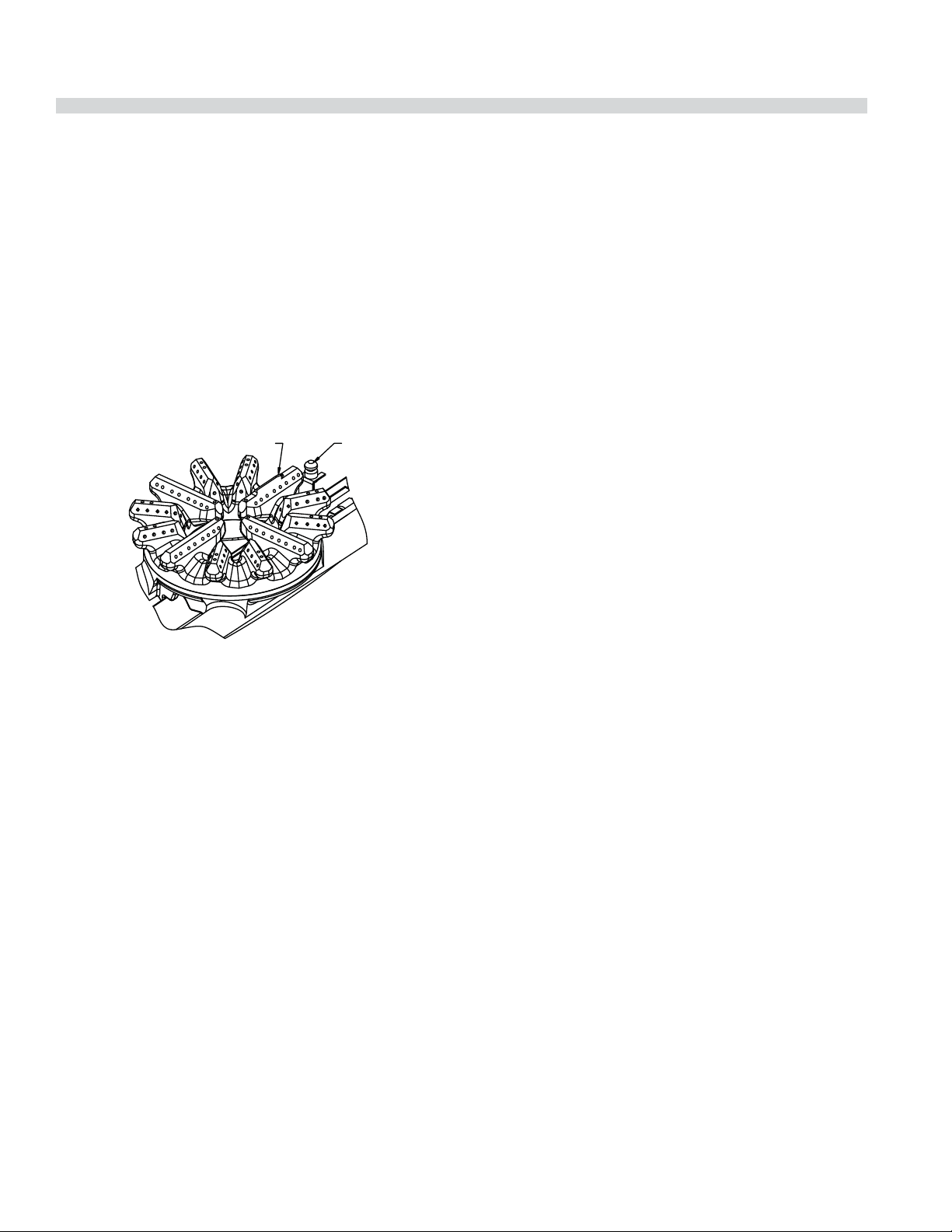
6. When reinstalling the open top burner head be sure
the burner ports are lined up correctly to the pilot. On
the cast burner head there is a raised indicator arrow to
ensure the burner is installed correctly.
RAISED ARROW INDICATOR
PILOT
hot water. Dry thoroughly. In damp climates, wipe down with
a light coating of oil to prevent rusting. Avoid excessive use
of water as this could damage the surface and the controls
below.
CAUTION: Do not use water on top plates while they are hot
or Do not use ice to cool plates.
NOTE: Hot top and front- red target hot top surface will
“tone” (blue/brown discoloration) from heat. This toning will
not diminish function or operation and is not a defect.
Griddle
To produce evenly cooked, browned griddle products, keep
griddle free from carbonized grease. Carbonized grease on
the surface hinders the transfer of heat from the griddle
surface to food product. This results in uneven browning
and loss of cooking e ciency, and worst of all, carbonized
grease tends to cling to grilled foods, giving them a highly
unsatisfactory and unappetizing appearance. To keep the
griddle clean and operating at peak performance, follow
these simple instructions:
A. AFTER EACH USE clean griddle thoroughly with a grill
scraper or spatula. Wipe o any excess debris left from
cooking process.
7. If an abnormal ame appears around the edges, it is
usually a sign of grease or dirt in the throat of the burner.
Remove the burner venturi (main body that the burner
heads sit on) to access the air shutter opening. Remove
grease and dirt from the air shutter area carefully. Do
not adjust the shutter setting. The air shutter allows the
proper amount of air to mix with the ow of gas coming
in from your valve/thermostat ori ce and should not be
adjusted unless by a licensed gas tter technician.
Cast Iron Top & Grates
Cast iron top and grate(s) can be cleaned with mild soap
and warm water. For baked on material, a wire brush can be
used. Dry thoroughly. Lightly coat with vegetable oil to help
prevent rust from forming.
Hot Tops and Front-Fired Target Hot Tops
While the surface is still slightly warm, wipe down with a
clean burlap cloth. Burnt on spillage should be scraped o . If
necessary, remove the plate and wash in a sink with soap and
B. ONCE A DAY clean griddle surface with a grill brick and
grill pad. Remove grease container and clean thoroughly,
in the same manner as any ordinary cooking utensil.
C. ONCE A WEEK clean griddle surface thoroughly. If
necessary, use a grill stone or grill pad over the griddle
surface. Rub with grain of the metal while still warm.
A detergent may be used on the plate surface to help
clean it, but care must be taken to be sure it is thoroughly
removed. After removal of detergent, the surface of the
plate should be covered with a thin lm of oil to prevent
rusting. To remove discolorations, use a non-abrasive
cleaner. Before re-using, the griddle must be reseasoned.
Keep griddle drain tube to grease container clear at all
times.
CAUTION This griddle plate is steel, but the surface is
relatively soft and can be scored or dented by careless use of
a spatula.
Be careful not to dent, scratch, or gouge the plate surface.
This will cause food to stick in those areas. Also, note, since
this is a steel griddle if a light coating of oil is not always
present rust will develop on exposed and uncoated areas.
Part # 4525587 Rev 4 (29 April 14)Page 20
Page 21

INSTRUCTIONS
D’INSTALLATION ET
D’UTILISATION
SÉRIE GARLAND GF
SENTRY CUSINIÈRES DE
RESTAURANT À GAZ
POUR VOTRE SÉCURITÉ:
NE PAS STOCKER NI UTILISER D’ESSENCE
OU D’AUTRES VAPEURS OU LIQUIDES
INFLAMMABLES À PROXIMITÉ DE CET
APPAREIL OU DE TOUT AUTRE APPAREIL
AVERTISSEMENT
UNE INSTALLATION, DES RÉGLAGES, DES
MODIFICATIONS, DES RÉPARATIONS
OU UN ENTRETIEN MAL FAITS PEUVENT
CAUSER DES DOMMAGES MATÉRIELS,
DES BLESSURES OU LA MORT. LIRE
SOIGNEUSEMENT LES INSTRUCTIONS
D’INSTALLATION, D’UTILISATION ET
D’ENTRETIEN AVANT D’INSTALLER OU DE
RÉPARER L’ÉQUIPEMENT.
Tous des 24, 36, 48, et 60 pouce les modèles larges.
LIRE TOUTES LES SECTIONS DU PRÉSENT
MANUEL ET LE CONSERVER POUR S’Y REPORTER
ULTÉRIEUREMENT.
CE PRODUIT A ÉTÉ HOMOLOGUÉ EN TANT
QU’ÉQUIPEMENT PROFESSIONNEL DE CUISSON
ET DOIT ÊTRE INSTALLÉ PAR DU PERSONNEL
PROFESSIONNEL TEL QUE SPÉCIFIÉ.
DANS L’ÉTAT DU MASSACHUSETTS, CE PRODUIT
DOIT ÊTRE INSTALLÉ PAR UN PLOMBIER OU UN
MONTEUR D’INSTALLATION AU GAZ.
Pour votre sécurité
Placer dans un endroit bien en vue les
instructions à suivre en cas d’odeur de gaz
détectée par l’utilisateur. Cette information peut
être obtenue auprès du fournisseur de gaz local
.
L’attention des utilisateurs est attirée sur le fait que l’entretien et les réparations doivent être e ectués par un agent
d’entretien autorisé par Garland utilisant des pièces de rechange d’origine Garland. Garland n’aura aucune obligation
en ce qui concerne n’importe quel produit mal installé, réglé, utilisé ou qui n’aurait pas été entretenu conformément aux
codes nationaux et locaux ou aux instructions d’installation fournies avec le produit ou n’importe quel produit dont le
numéro de série aurait été mutilé, oblitéré ou supprimé ou qui aurait été modi é ou réparé avec des pièces non autorisées
ou par des agents d’entretien non autorisés. Pour obtenir la liste des agents de service autorisés, consulter le site web
de Garland à : http://www.garland-group.com. Les renseignements contenus dans le présent document (y compris la
conception et les spéci cations des pièces) peuvent être remplacés ou modi és sans préavis.
Garland Commercial Ranges, Ltd.
1177 Kamato Road, Mississauga, Ontario L4W 1X4 CANADA
Phone: 905-624-0260
Fax: 905-624-5669
Pièce nº 4525587 Rev 4 (29 Apr 14) Page 21
General Inquires 1-95-624-0260
USA Sales, Parts and Service 1-800-424-2411
Canadian Sales 1-888-442-4526
Canada or USA Parts/Service 1-800-427-6668
Page 22

INFORMATIONS IMPORTANTES
AVERTISSEMENT
Ce produit contient des produits chimiques reconnus par l’état de Californie comme causant
le cancer et/ou des malformations congénitales ou d’autres problèmes de reproduction.
L’installation et l’entretien de ce produit peut vous exposer aux poussières de laine de
verre/fibres céramiques. L’inhalation de ces particules de laine de verre ou de fibres céramiques
est reconnue par l’état de Californie comme causant le cancer. L’utilisation de ce produit peut vous
exposer au monoxyde de carbone en cas de mauvais réglage. L’inhalation de monoxyde de carbone
est reconnue par l’état de Californie comme pouvant causer des malformations congénitales ou
d’autres problèmes reproductifs.
Maintenir les abords de l’appareil
dégagés et ne pas y stocker de produits combustibles
Pièce nº 4525587 Rev 4 (29 Apr 14)Page 22
Page 23

TABLE DES MATIÈRES
INFORMATIONS IMPORTANTES . . . . . . . .22
DIMENSIONS ET SPÉCIFICATIONS . . . . . . 24
Désignations Des Modèles De Base Et Débits
Calori ques Totaux . . . . . . . . . . . . . . . . . . . . . . . . .25
Dégagements . . . . . . . . . . . . . . . . . . . . . . . . . . . . . .26
Pression du Gaz et Débits Calori ques des
Brûleurs Individuels . . . . . . . . . . . . . . . . . . . . . . . . . 26
Amérique du Nord . . . . . . . . . . . . . . . . . . . . . . 26
CE Et Export Général . . . . . . . . . . . . . . . . . . . . 26
Taux réduits d’entrée . . . . . . . . . . . . . . . . . . . . 27
Remarque : La pression du collecteur doit
être mesurée au bout uni d’essai situé sur le
tube du collecteur de gaz de ¾ po.. . . . . . . 27
Australie . . . . . . . . . . . . . . . . . . . . . . . . . . . . . . . . 27
Dimension d’entrée du gaz . . . . . . . . . . . . . . . . . .27
Catégories de Gaz Agréées CE . . . . . . . . . . . . . . .27
INTRODUCTION. . . . . . . . . . . . . . . . . . . . . . .28
Plaque Signalétique . . . . . . . . . . . . . . . . . . . . . . . .28
Informations de Sécurité . . . . . . . . . . . . . . . . . . . . 28
Kit d’interconnexion au Gaz en Option
N° 4523975 . . . . . . . . . . . . . . . . . . . . . . . . . . . . . . . . .33
ESSAIS ET RÉGLAGES. . . . . . . . . . . . . . . . . . 34
Essais . . . . . . . . . . . . . . . . . . . . . . . . . . . . . . . . . . . . . . .34
UTILISATION. . . . . . . . . . . . . . . . . . . . . . . . . . 35
Technologie à Détecteur de Flamme . . . . . . . . 35
Comment Fonctionne la Technique
de Détection de Flamme . . . . . . . . . . . . . . . . . . . .35
Brûleurs de Plaque Ouverte . . . . . . . . . . . . . . . . .35
Fours (standard) . . . . . . . . . . . . . . . . . . . . . . . . . . . .36
Fours à Convection . . . . . . . . . . . . . . . . . . . . . . . . .37
Grils à Thermostat . . . . . . . . . . . . . . . . . . . . . . . . . .38
Gril/Rôtissoire . . . . . . . . . . . . . . . . . . . . . . . . . . . . . .38
Arrêt de la Cuisinière . . . . . . . . . . . . . . . . . . . . . . . .39
INFORMATIONS D’APPLICATION DES
PRODUITS . . . . . . . . . . . . . . . . . . . . . . . . . . . .39
Généralités . . . . . . . . . . . . . . . . . . . . . . . . . . . . . . . . . 39
Brûleurs Ouverts . . . . . . . . . . . . . . . . . . . . . . . . . . . .39
INSTALLATION. . . . . . . . . . . . . . . . . . . . . . . .29
Implantation . . . . . . . . . . . . . . . . . . . . . . . . . . . . . . . .29
Appareils Équipés de Roulettes . . . . . . . . . . . . . 29
Installation de l’étagère sur le dosseret . . . . . . .29
Instructions de Montage de Dosseret Avec
Étagère Haute ou de Salamandre . . . . . . . . . . . .30
Air de Ventilation . . . . . . . . . . . . . . . . . . . . . . . . . . . 31
Clause Spéci que à L’australie . . . . . . . . . . . . . . .31
Connexions Électriques (Le Cas Échéant) . . . . .31
Connexion du Gaz . . . . . . . . . . . . . . . . . . . . . . . . . .31
Préparation Finale . . . . . . . . . . . . . . . . . . . . . . . . . .32
Pièce nº 4525587 Rev 4 (29 Apr 14) Page 23
ENTRETIEN ET NETTOYAGE . . . . . . . . . . . .40
Apprêtage . . . . . . . . . . . . . . . . . . . . . . . . . . . . . . . . . .40
Gril . . . . . . . . . . . . . . . . . . . . . . . . . . . . . . . . . . . . . 40
Grilles Supérieures en Fonte . . . . . . . . . . . . . 40
Acier Inoxydable . . . . . . . . . . . . . . . . . . . . . . . . . . . .40
Plaques de Cuisson . . . . . . . . . . . . . . . . . . . . . . . . .40
Intérieur du Four (Émail Vitri é) . . . . . . . . . . . . . . 41
Brûleurs de Plaque Ouverte . . . . . . . . . . . . . . . . . 41
Plaques et Grilles en Fonte . . . . . . . . . . . . . . . . . . 41
Plaques de cuisson et plaques de cuisson
chau ées par l’avant à chaleur ciblée . . . . . . . . 41
Nettoyage du Gril . . . . . . . . . . . . . . . . . . . . . . . . . . . 42
Page 24

DIMENSIONS ET SPÉCIFICATIONS
Vue de dessus
Les largeurs des modèles varient en fonction de la série du
modèle. (Voir tableau à gauche)
FICHE ÉLECTRIQUE
(LE CAS ÉCHÉANT)
3-1/2"
[89mm]
2-1/4"
[57mm]
27-1/4"
[692mm]34-1/2"
[876mm]
5"
[127mm]
Série Largeur
GF24 600mm (23-5/8 Po)*
GF36 900mm (35-1/2 Po)* Illustré
GF48 1 200mm (47-1/4 Po)
GF60 1 500mm (59-1/2 Po)
*Base de la cuisinière ou plaque
de cuisson modulairep
Modèles à Plaque de Cuisson Modulaire GF24-_T
ou GF36-_T Vue de Côté
9-3/8" [238mm]
15-5/8"
[396mm]
Vue de côté de la série GF
(Montrant la base de convection le cas échéant).
12-1/8"
[307mm]
18-3/8"
[466mm]
39-3/8"
[1000mm]
DOSSERET À
PROFIL BAS
13-7/8"
[352mm]
AJOUTER
AVEC
LA PORTE
OUVERTE
31-1/8"
[791mm]
3-7/8" [98mm]
AJOUTER POUR
FOUR À CONVECTION
51"
[1290mm]
DOSSERET STD
AVEC
ÉTAGÈRE HAUTE
(EN OPTION)
GF Série 60” Vue Latérale du Gril/de la Rôtissoire Surélevés
12-1/8"
DÉGAGEMENT ENTRE LE HAUT DE LA
PLAQUE DU GRIL ET L’ÉTAGÈRE HAUTE
EN OPTION 14-3/4" [374mm]
DÉGAGEMENT ENTRE LE DESSUS DE LA
GRILLE ET L’ÉTAGÈRE HAUTE
EN OPTION 18-3/8" [466mm]
13-7/8"
[352mm]
AJOUTER
AVEC
LA PORTE
OUVERTE
[307mm]
31-1/8"
[791mm]
1"
[25mm]
ENTRÉE
DU GAZ
41"
[1041mm]
DOSSERET
À PROFIL BAS
3-7/8" [98mm]
AJOUTER POUR
FOUR À CONVECTION
51"
[1296mm]
DOSSERET STD
AVEC ÉTAGÈRE
HAUTE
Pièce nº 4525587 Rev 4 (29 Apr 14)Page 24
Page 25

DIMENSIONS ET SPÉCIFICATIONS suite
Désignations Des Modèles De Base Et Débits Calori ques Totaux
Model #* Description
BTU/H
GF/GFE24-4L
GF24-T
GF/GFE36-6R
GFE36-6C
GF36-T
GF/GFE36-TTR
GFE36-TTC
GF/GFE48-LL
GF/GFE60-10RR
GFE60-10RC
GFE60-10CC
GF/GFE60-6R24RR
GFE60-6R24RC
GFE60-6R24CC
GF/GFE60-6R24RS
Unité de 24 po (600 mm) de taille nominale,
4 brûleurs ouverts, four économiseur d’espace
Unité de 24 po (600 mm) de taille nominale,
4 brûleurs ouverts, plaque de cuisson modulaire
Unité de 36 po (900 mm) de taille nominale,
6 brûleurs ouverts, four standard
Unité de 36 po (900 mm) de taille nominale,
6 brûleurs ouverts, four à convection
Unité de 36 po (900 mm) de taille nominale,
6 brûleurs ouverts, plaque de cuisson modulaire
Unité de 36 po (900 mm) de taille nominale, 2 sections
de plaque de cuisson chau ée par l’avant à chaleur
ciblée, four standard
Unité de 36 po (900 mm) de taille nominale, 2 sections
de plaque de cuisson chau ée par l’avant à chaleur
ciblée, four à convection
Unité de 48 po (1200 mm) de taille nominale,
8 brûleurs ouverts, 2 fours économiseur d’espace
Unité de 60 po (1500 mm) de taille nominale,
10 brûleurs ouverts, 2 fours standard
Unité de 60 po (1500 mm) de taille nominale,
10 brûleurs ouverts, 1 four standard, 1 four à convection
Unité de 60 po (1500 mm) de taille nominale,
10 brûleurs ouverts, 2 fours à convection
Unité de 60 po (1500 mm) de taille nominale,
6 brûleurs ouverts, 24 po (610 mm),
gril/rôtissoire surélevé ,2 fours standard
Unité de 60 po (1500 mm) de taille nominale, 6 brûleurs
ouverts, 24 po (610 mm), gril/rôtissoire surélevé, 1 four
standard, 1 four à convection
Unité de 60 po (1500 mm) de taille nominale, 6 brûleurs
ouverts,24 po (610 mm), gril/rôtissoire surélevé, 2 fours
à convection
Unité de 60 po (1500 mm) de taille nominale, 6 brûleurs
ouverts, 24 po (610 mm), gril/rôtissoire surélevé ,1 four
standard, 1 base de rangement
136,000
104,000
194,000
194,000
156,000
100,000
100,000
272,000
336,000
336,000
336,000
265,000
265,000
265,000
227,000
Débit
Gaz Naturel Gaz Propane
CE
Estimation kWBTU/H
41.50
30.40
56.70
56.70
45.60
29.1
29.1
79.60
98.20
98.20
98.20
76.80
76.80
76.80
65.70
132,000
104,000
188,000
188,000
156.000
94,000
94,000
264,000
324,000
324,000
324,000
253,000
253,000
253,000
221,000
CE
Estimation
kW
39.70
30.40
54.90
54.90
45.60
25.5
25.5
77.20
94.60
94.60
94.60
73.20
73.20
73.20
63.90
Pièce nº 4525587 Rev 4 (29 Apr 14) Page 25
Page 26

DIMENSIONS ET SPÉCIFICATIONS suite
Unité de 60 po (1500 mm) de taille nominale, 6 brûleurs
GFE60-6R24CS
* Les modèles commençant par le pré xe GFE ont des systèmes d’allumage par étincelles électriques pour les veilleuses.
Débits calori ques pour installations jusqu’à 2 000 pi (610 m) au-dessus du niveau de la mer.
Chaque 12” (305mm) La section Plaque de Cuisson est 5.3kW, remplaçant 2 brûleurs ouverts (7.6kW chacun).
Dégagements
Dégagements Applicables Pour Tous les Modèles Sauf Indication Contraire
Minimum Mur Combustible 14 po (356mm) 6 po (152mm) 6 po(152mm)
Minimum Mur Non Combustible 0 Po 0 po 0 po
Pression du Gaz et Débits Calori ques des Brûleurs Individuels
Amérique du Nord
ouverts, 24 po (610 mm), gril/rôtissoire surélevé, 1 four
à convection, 1 base de rangement
Côtés Plaque
de Cuisson
Modulaire
Surface
Côtés de la
Cuisinière
227,000
Arrière
65.70
221,000
63.90
Nat.
Série GF Garland
Plaque Ouverte (Détecteur de Flamme) 26,000 26,000
Plaque de Cuisson FF (au Lieu de Deux Brûleurs Ouverts) 18,000 18,000
Modèles à plaque à chaleur ciblée de 36 po seulement, par
section
Gril (au Lieu de 2 Brûleurs Ouverts) (Thermostat) 18,000 18,000
Gril Rôtissoire Surélevé (3 Brûleurs) 3 @ 11,000 3 @ 11,000
Brûleur de Four de 26 Po (H-Cast) (Standard ou Convection) 38,000 32,000
Four Économiseur d’espace (H-Cast) 32,000 28,000
4,5 Po c.e. Collecteur
BTU/h BTU/h
3@10,333 3@10,333
10 Po c.e. Collecteur
Gpl
CE Et Export Général
Nat. (G20) ,
Série GF Garland
Plaque Ouverte (Détecteur de Flamme) 7.6 7.6
Plaque de Cuisson FF (au Lieu de Deux Brûleurs Ouverts) 5.3 5.0
Modèles à plaque à chaleur ciblée de 36 po seulement, par
section
Gril (au Lieu de 2 Brûleurs Ouverts) (Thermostat) 5.3 5.3
Gril Rôtissoire Surélevé (3 Brûleurs) 3 @ 3.0 3 @ 3.0
Brûleur de Four de 26 Po (H-Cast) (Standard ou Convection) 11.1 9.3
Four Économiseur d’espace (H-Cast) 9.4 8.2
11,2 Mbar Collecteur
kW kW
3.0 3@2.7
Gpl (G31),
24,9 Mbar Collecteur
Pièce nº 4525587 Rev 4 (29 Apr 14)Page 26
Page 27

DIMENSIONS ET SPÉCIFICATIONS suite
Taux réduits d’entrée
Les estimations d’entrée d’aprproximate pour les brûleurs supérieurs réglables ont placé au BAS:
Garland GF Series
Brûleur de Plaque Ouverte (Détecteur de Flamme) 2.0 0.21 4.2 0.17
Brûleur de Plaque de Cuisson (Détecteur de Flamme) 2.75 0.29 4.9 0.20
Gril (Thermostat) 3.0 0.32 2.0 0.08
Gril Rôtissoire Surélevé (3 Brûleurs Total) 3.0 0.32 5.9 0.24
Modèles à plaque à chaleur 2.7 0.28 4.0 0.16
Remarque : La pression du collecteur doit être mesurée au bout uni d’essai situé sur le tube du collecteur de gaz de ¾ po.
Australie
NAT(G20) LPG(G31)
kW m3/h kW m3/h
Série GF Garland
Plaque ouverte (détecteur de amme)
Plaque de cuisson FF (au lieu de deux brûleurs ouverts)
Plaque de cuisson chau ée par l’avant (chaleur ciblée)
Gril (au lieu de 2 brûleurs ouverts) (Thermostat)
Gril Rôtissoire Surélevé (3 brûleurs)
Brûleur de four de 26 po (H-Cast) (Standard
ou Convection)
Four Économiseur d’espace (H-Cast)
Dimension d’entrée du gaz
Largeur du Modèle Connexion
23-5/8 po (600 mm) et
35-1/2 po (900 mm)
47-1/4 po (1 200 mm) et
59-1/2 po (1 500 mm)
Connexion arrière du gaz
3/4 po NPT
Connexion arrière du gaz
1 po NPT
Catégories de Gaz Agréées CE
Nat. 1,0 kPa Collecteur GPL, 2,49kPa Collecteur
MJ/h Injecteur MJ/h Injecteur
30.6 37 (2.64mm) 28.49 53 (1.51mm)
19.0 47 (1.99mm) 18.15 1.2mm
36.5 52(1.61mm) 36.5 1.0mm
19.0 47 (1.99mm) 18.15 1.2mm
30.0 47 (1.99mm) 34.82 61 (0.99 mm)
40.09 30 (3.26mm) 33.76 50 (1.78mm)
33.7 33 (2.87mm) 27.96 52 (1.61mm)
Le CE Modèle le
Raccordement (IS07-1)
3/4po (19.1 mm) BSPT
1po (25.4 mm) BSPT
Pays Catégorie De Gaz Type De Gaz Pression (mbar)
AT, CH, CY, CZ, DK, EE, ES, FI, GB, GR, HR, IE, IT,
LT, LV, NO, PT, RO, SE, SI, SK, TR
BE, CH, CZ, ES, FR, GB, GR, HR, IE, IT, LU, PL, PT I
AT, BE, CH, CZ, DE, ES, FR, GB, HU, NL I
CH, CZ, ES, GB, GR, HR, IE, IT, PT II
CH, CZ, ES, GB, II
I
2H
3P
3P
2H3P
2H3P
G20 20
G31 37
G31 50
G20 20
G31 37
G20 20
G31 50
Pièce nº 4525587 Rev 4 (29 Apr 14) Page 27
Page 28

INTRODUCTION
1. Assurez-vous que la caisse n’a subi aucun dommage
pendant son transport. Retirez soigneusement l’unité
de son carton ou sa caisse, et essayez de nouveau de
déceler tout dommage éventuel. Vous devez signaler
immédiatement au transporteur tout dommage
occasionné à l’appareil.
2. Les ls de fer retenant les brûleurs et autres matériaux
d’emballage doivent être retirés des appareils. Tout
le matériel de protection couvrant les pièces en acier
inoxydable doit également être retiré.
3. Tout l’équipement est livré avec pieds de 6 po (152 mm)
sauf indication contraire, à savoir estrade pour montage
de plinthe, roulettes ou pieds à bride montés sur tablier
Les unités de 48 po (1 219 mm) et 60 po (1 524 mm) de
large ont des pieds montés en usine. Un montage sur
base est nécessaire quand la cuisinière est installée sur un
plancher combustible.
4. Le type de gaz et la pression d’alimentation pour lesquels
l’équipement a été réglé en usine sont notés sur la plaque
signalétique et sur l’emballage. Vous devez utiliser ce type
de gaz.
5. Ne retirez pas de l’appareil les étiquettes, avertissements
ou plaques signalétiques apposés de façon permanente,
car cela peut annuler la garantie du fabricant.
Plaque Signalétique
Tous les débits calori ques des brûleurs sont indiqués sur la
plaque signalétique de chaque appareil et sont facilement
lisibles en ouvrant la porte émaillée sous le panneau de
commande.
Informations de Sécurité
AVERTISSEMENT : Des pièces accessibles peuvent devenir
chaudes pendant l’utilisation. Maintenir les jeunes enfants
éloignés.
Cet appareil est pour à usage professionnel et devrait
seulement être employé par le personnel quali é.
Cet appareil n’est pas destiné à être utilisé par des
personnes (y compris des enfants) ayant des capacités
physiques, sensorielles ou mentales réduites ou un manque
d’expérience et de connaissances à moins qu’elles n’aient
reçu une supervision ou des instructions concernant
l’utilisation de cet appareil d’une personne responsable de
leur sécurité.
Pièce nº 4525587 Rev 4 (29 Apr 14)Page 28
Page 29

INSTALLATION
Ce produit a été homologué en tant qu’équipement de
cuisson commercial et doit être installé par du personnel
professionnel comme spéci é. CET APPAREIL N’EST PAS
RECOMMANDÉ POUR UNE INSTALLATION RÉSIDENTIELLE.
Dans la mesure du possible, Garland suggère que les
travaux d’installation, de maintenance et de réparation
soient e ectués par votre agence de service locale agréée
par Garland/US Range.
Implantation
Le plancher sur lequel l’appareil doit être posé doit pouvoir
supporter le poids de l’appareil et de tout l’équipement
auxiliaire. Les appareils avec fours doivent être équipés
de pieds ou de roulettes s’ils sont installés sur un plancher
combustible. Un dégagement su sant doit être prévu pour
l’entretien et l’utilisation.
Appareils Équipés de Roulettes
1. L’installation sera faite avec un raccord conforme à la
norme Connectors for Movable Gas Appliances, ANSI
Z21.69/CSA 6.16 Addenda Z21.69B-2006/CSA 6.16B-2006
(ou la dernière édition) et un raccord rapide conforme à
la norme Standard for Quick Disconnects for Use with Gas
Fuel, ANSI Z21.41/CSA 6.9 Addenda Z 21.41A-2005/CSA
6.16A-2005 (ou la dernière édition).
2. Les roulettes avant de l’appareil sont dotées de freins
qui limitent les déplacements de l’appareil sans que
le connecteur ou le raccord rapide ou sa tuyauterie
n’interviennent pour limiter les mouvements de
l’appareil.
Appareils Équipés de Pieds
1 Soulever l’avant de l’appareil et l’immobiliser. Ne pas
coucher l’appareil sur l’arrière.
2. Les pieds sont letés pour être vissés facilement dans les
trous prévus sous la cuisinière.
3. Une fois les pieds vissés en place, ils peuvent être réglés
pour mettre l’appareil de niveau et compenser un sol
inégal.
Installation de l’étagère sur le dosseret
Remarque : L’étagère peut être installée avant ou après avoir
installé le dosseret sur la cuisinière.
1. Desserrer les 4 boulons à l’avant du dosseret d’environ
1/4 po (6 mm).
2. Aligner les 4 trous allongés à l’arrière de l’étagère avec les
4 boulons sur le dosseret.
3. Faire glisser l’étagère vers le bas jusqu’à ce que les 4
boulons soient engagés dans la partie allongée du trou
de serrure.
4. Serrer les 4 boulons pour immobiliser l’étagère.
5. Sur les appareils de 60 po seulement, installer une vis
Parker dans le trou sous l’étagère dans le dosseret et
serrer la vis.
3. Noter que le dispositif de xation requis est xé à une
bride sur la friteuse (le point de xation est situé sur la
roulette arrière gauche de la friteuse) et, s’il est nécessaire
de détacher le dispositif de xation, ne pas oublier de
le rattacher une fois la friteuse remise dans sa position
d’origine.
Pièce nº 4525587 Rev 4 (29 Apr 14) Page 29
BOULONS
DE MONTAGE
DOSSERET
ÉTAGÈRE
VIS
AUTOTARAUDEUSE
Page 30

INSTALLATION suite
Instructions de Montage de Dosseret Avec
Étagère Haute ou de Salamandre
1. L’arrière de la cuisinière doit être facilement accessible.
2. Consulter les instructions d’installation jointes à la
salamandre pour d’autres instructions sur ces appareils.
3. Placer le dosseret, l’étagère haute, la salamandre ou la
salamandre à fromage sur l’arrière de la cuisinière, en
faisant glisser les supports dans les ouvertures des côtés
de carrosserie principale.
4. Pour les cuisinières avec grils, faire attention lors du
montage du dosseret ou de l’étagère haute. Le panneau
avant du dosseret ou de l’étagère haute en acier
inoxydable est doté d’une lèvre d’extrusion à la partie
inférieure. Cette lèvre NE DOIT PAS passer sur le dosseret
du gril; dans le cas contraire, le dosseret ne s’adaptera pas
correctement et l’évacuation des fumées de la cuisinière
se fera mal. Consulter l’illustration pour une installation
correcte.
Installation Correct
FIXER LE PARE-ÉCLABOUSSURES
DU GRIL SUR LA BRIDE ARRIÈRE DU GRIL
(EXPÉDIÉ SUR LE DESSUS DU GRIL)
LA LÈVRE DU DOSSERET
DERRIERE LA BRIDE
ARRIÈRE DU GRIL ET
SUR LA BRIDE
ANGULAIRE
BRIDE
ANGULAIRE
Installation incorrecte
BACKGUARD
LIP ON BACK
FLANGE
OF GRIDDLE
DE NIVEAU
AVEC LE
PANNEAU
LATÉRAL
NOT FLUSH
WITH
SIDE PANEL
DOSSERET
PARE-ÉCLABOUSSURES
DÉTAIL
5. Bien xer les supports aux côtés du boîtier des brûleurs
avec (4)vis à tôle fournie.
DROIT
CÔTÉ DE
CARROSSERIE
PRINCIPALE
VIS À TÔLE
(4 PIÈCES)
Pièce nº 4525587 Rev 4 (29 Apr 14)Page 30
Page 31

INSTALLATION suite
Air de Ventilation
Les notes suivantes dont destinées à donner une orientation
générale. Pour des recommandations détaillées, se
référer aux codes applicables dans le pays de destination.
Ces appareils seront installés dans une chambre avec
la ventilation su sante d’empêcher l’occurrence des
concentrations dangereuses des sous-produits de
combustion.
La salle où se trouve l’appareil doit être ventilée de façon
permanente. La surface minimale e cace de l’évent est liée
au débit calori que nominal maximum de l’appareil et doit
être de 4,5 cm² par Kw au delà de 7 kW.
Une bonne ventilation est absolument essentielle pour un
rendement optimal. La méthode idéale de ventilation de
l’équipement à plaques ouvertes est une hotte correctement
conçue, se prolongeant de six pouces (152 mm) de tous les
côtés de l’appareil et située à six pieds six pouces (1981 mm)
du sol.
Les évents doivent être de dimensions su santes pour
compenser les e ets des ventilateurs d’aspiration des locaux.
Une forte aspiration risque de créer une dépression dans
la pièce. Pour qu’un ventilateur d’extraction fonctionne
correctement, la quantité d’air de remplacement doit être
égale à la quantité d’air évacuée. Un déséquilibre entre
l’air évacué et l’air de remplacement peut réduire les
performances de l’appareil.
Tous les brûleurs à gaz et veilleuses ont besoin de
su samment d’air pour fonctionner. Ne pas placer d’objets
encombrants devant les appareils, car ils pourraient obstruer
l’admission d’air par l’avant.
Clause Spéci que à L’australie
Cet appareil doit être installé conformément aux instructions
du fabricant, aux règlements locaux relatifs aux raccords de
gaz et aux exigences du code d’installation AS 5601. Tous
les réglages des brûleurs doivent être faits par un technicien
quali é spécialiste des appareils à gaz.
Connexions Électriques (Le Cas Échéant)
IMPORTANT – Cet appareil doit être relié à la terre
conformément aux codes locaux et au code national de
l’électricité.
Modèles À Four À Convection 220/240 Volts
Quand cet appareil est commandé et équipé pour un
fonctionnement en 220/240 volts, la ligne d’alimentation
doit être branchée aux connecteurs de câblage situés à
l’intérieur de la boîte de raccordement à l’arrière de l’appareil.
Pour faciliter le branchement de la ligne d’alimentation, la
boîte de raccordement à un couvercle amovible.
La connexion permanente au réseau de distribution
électrique doit être conforme aux codes locaux ou, en
l’absence de codes locaux, au code électrique national.
Connexion du Gaz
Consulter la compagnie locale de gaz au moment de la
plani cation de l’installation de façon à établir la disponibilité
d’une alimentation en gaz su sante et de s’assurer que le
compteur correspond au débit nécessaire. La canalisation
entre le compteur et les appareils doit être de diamètre
approprié.
Réglementation légale
Dans les pays européens, l’installation doit être faite par une
personne compétente et conformément aux règlements
concernés, codes de pratique et publications connexes du
pays de destination
Aux États-Unis, l’installation doit être conforme au National
Fuel Gas Code ANSI Z223.1, ou la dernière édition, la norme
NFPA No.54 – dernière édition/ou le code local pour assurer
un fonctionnement sécuritaire et e cace. Au Canada,
l’installation doit être conforme à la norme CSA B149.1 et aux
codes locaux.
Pièce nº 4525587 Rev 4 (29 Apr 14) Page 31
Tous les appareils xes (non mobiles) DOIVENT être équipés
d’un robinet de gaz manuel en amont de l’appareil pour
pouvoir isoler l’appareil lors de toute intervention d’entretien
ou de nettoyage. Un raccord union ou tout autre moyen
de déconnexion doit être installé entre le robinet de gaz et
l’appareil.
Un robinet à commande manuelle doit être installé sur
l’arrivée de gaz dans la cuisine pour permettre d’isoler la
cuisine en cas d’urgence. Chaque fois que cela est possible,
ce robinet sera installé soit à l’extérieur de la cuisine ou près
d’une sortie dans un endroit facile d’accès.
Page 32

INSTALLATION suite
Lorsque cela est impossible, un système automatique de
robinet d’isolement doit être installé à un endroit facile
d’accès près de la sortie.
L’avertissement suivant DOIT être a ché à l’endroit
d’installation du robinet d’isolement ou du système
automatique :
«TOUS LES ROBINETS DE BRÛLEURS ET DE VEILLEUSES EN
AMONT DOIVENT ÊTRE MIS EN POSITION D’ARRÊT AVANT
D’OUVRIR L’ALIMENTATION. APRÈS UN PÉRIODE D’ARRÊT
PROLONGÉE. PURGER AVANT DE REBRANCHER LE GAZ».
Instructions Avant Installation
Avant le montage et le branchement, véri er l’alimentation
en gaz.
A. Le type de gaz pour lequel l’appareil est équipé est
estampillé sur la plaque signalétique située sur le
panneau intérieur de porte. Brancher un appareil
estampillé « NAT » au gaz naturel et un appareil
estampillé « PRO » au gaz propane.
B. S’il s’agit d’une installation neuve, faire véri er par
le fournisseur de gaz le diamètre du compteur et
des conduites a n de s’assurer que l’appareil reçoit
une pression de gaz su sante pour fonctionner
correctement.
C. S’il s’agit d’un équipement supplémentaire ou de
remplacement, demander au fournisseur de gaz de
véri er la pression a n de s’assurer que le compteur et les
conduites existants alimenteront l’appareil sans chute de
pression supérieure à 0.15 Kpa de colonne d’eau.
NOTA : La pression du gaz doit être véri ée quand l’appareil
est installé et que tous les autres équipements sur la même
conduite sont allumés. La pression du collecteur de gaz doit
être identique à celle spéci ée sur la plaque signalétique. Si
nécessaire, les réglages de pression peuvent être e ectués
au régulateur de pression fourni sur chaque appareil.
Le régulateur de pression de l’appareil fourni par l’usine est
préréglé à la pression correcte du collecteur La pression du
collecteur peut nécessiter une véri cation et un réglage
lors de l’installation. Laisser au moins un brûleur s’allumer
et fonctionner pendant la véri cation de la pression du
collecteur au bout uni d’essai situé sur le collecteur de
l’appareil et ajuster le régulateur de pression de l’appareil en
conséquence.
Cet appareil et son robinet d’arrêt du gaz individuel (non
fourni par le fabricant) doivent être débranchés du système
d’alimentation en gaz lors de tout essai de pression de ce
système à des pressions dépassant 1/2 lb/po2 (3,45 kPa). Cet
appareil doit être isolé du système d’alimentation en gaz
en fermant son robinet d’arrêt individuel (non fourni par le
fabricant) lors de tout essai du système d’alimentation en gaz
à des pressions d’essai supérieures ou égales à 1/2 lb/po2
(3,45 kPa).
Préparation Finale
NOTA : Toute nouvelle cuisinière a un revêtement plasti é
pour protéger le ni des rayures pendant le transit. Ce
lm plastique protecteur doit être retiré avant de faire
fonctionner la cuisinière.
D. S’assurer que les tuyauteries, joints et branchements
neufs ont été exécutés proprement et ont été purgés
de façon à ce que la graisse à letage, les copeaux,
etc. ne bouchent pas les veilleuses, robinets et/ou les
commandes. Utiliser du produit d’étanchéité pour joint
homologué pour une utilisation avec le gaz de pétrole
liqué é.
Pièce nº 4525587 Rev 4 (29 Apr 14)Page 32
Page 33

INSTALLATION suite
Kit d’interconnexion au Gaz en Option
N° 4523975
Pour brancher les salamandres à monter sur cuisinière avec
la cuisinière.
5
TO INLET OF SALAMANDER/
8
15 4531608
14
13
12
11
10
9
8
7 2640800
6 2640700
5 3013000
4
3
2
1
ITEM NO.
CHEESEMELTER MANIFOLD
ATTACH SUPPORT CLAMP (ITEM 7 - 2640800)
TO SUPPORT BRACKET ( ITEM 6 - 2640700)
WITH (2)#10-24 SELF-TAPPING SCREWS (ITEM 12
F32 - NOT SHOWN) PROVIDED.
MARK HOLE LOCATIONS AND MOUNT
SUPPORT BRACKET (ITEM 6 - 2640700) TO RANGE
BACK WITH (2)#10-16 TEKS SELF-DRILL/TAP
SCREWS (ITEM 11 - F67 - NOT SHOWN) PROVIDED.
G01738-11
2127503/2127500
F32
F67
G03716-1
G01738-5
G01474-9
G01963-1
G01474-5
G01738-14
NAT: 2127502/4525047
PRO: 2127500/4525048
PART NUMBER
REGULATOR - 6.0"w.c. NATURAL GAS
OR 10.0"w.c. PROPANE GAS
(SUPPLIED WITH SALAMANDER/
CHEESEMELTER)
6.0"wc 3/4"NPT REG. NATURAL GAS/10"wc 3/4" NPT REG. PROPANE GAS - SUPPLIED WITH SALAMANDER/CHEESEMELTER
4.5"wc 3/4"NPT/3/4" ISO 7-1 REG. NATURAL GAS OR 10"wc 3/4"NPT/3/4" ISO 7-1 REG. PROPANE GAS - SUPPLIED W/RANGE
13
9
3
3/4" X 51" X 33" TUBING
3/4" NPT X 3.5" PIPE NIPPLE
SCREW-10-24X1/2" PAN HD SELF-TAP TYPE F (NOT SHOWN)
SCREW - #10-16 X 1/2" HEX WASHER HEAD TEKS SELF DRILL/TAP (NOT SHOWN)
3/4" NPT X 3/4" NPT X 1" NPT REDUCING TEE
3/4" NPT X 6.5" PIPE NIPPLE
3/4" NPT X 1/2" NPT 90 DEG. REDUCING ELBOW
PIPE SUPPORT BRACKET CLAMP
PIPE SUPPORT BRACKET
3/4" CC X 3/4" NPT STRAIGHT FITTING
90 DEGREE ELBOW 3/4" NPT (ONE SUPPLIED WITH RANGE)
3/4" NPT X 2IN PIPE NIPPLE (ONE SUPPLIED WITH RANGE)
3/4" NPT PIPE UNION
DESCRIPTION
La cuisinière série GF de Garland peut être équipée d’une
salamandre à gaz à monter sur cuisinière. Les salamandres
peuvent être connectées de façon indépendante ou être
connectées à la cuisinière. Voir le dessin pour les di érentes
options de montage sur une cuisinière de 36 po (900 mm),
48 po (1 200 mm) ou 60 po (1 500 mm).
CUT TUBING (ITEM 15 - 4531608) TO SIZE AS REQUIRED
TO SUIT SALAMANDER/CHEESEMELTER TOP OR REAR
MANIFOLD INLET CONNECTION
15
SUPPLIED WITH RANGE
3
5
SUPPLIED WITH RANGE
2
REGULATOR - 4.5" w.c. NATURAL GAS
OR 10.0" w.c. PROPANE GAS
(SUPPLIED WITH RANGE)
1
2
4
2
7
14
10
1" NPT GAS SUPPLY
CONNECTION
1
1
1
2
2
1
1
1
Optional Interconnect Gas Kit
1
QTY
1
2
1
2
3
1
36in (900mm) G/U/X
Part # 4531606
TO INLET OF RANGE
MANIFOLD
6
Pièce nº 4525587 Rev 4 (29 Apr 14) Page 33
Page 34

ESSAIS ET RÉGLAGES
TO INLET OF SALAMANDER/
CHEESEMELTER MANIFOLD
FOR LEFT-MOUNTED SALAMANDER/CHEESEMELTER
SUBSTITUTE COMPONENTS SHOWN FOR ITEM 17 CIRCLED IN ADJACENT VIEW
6
TO INTER-CONNECT TUBING ( ITEM 18 - 4531608)
17
10
MARK HOLE LOCATIONS AND MOUNT
SUPPORT BRACKET (ITEM 9 - 4531602 ) TO RANGE
BACK WITH (2) #10-16 TEKS SELF-DRILL/TAP
SCREWS (ITEM 14 - F67 - NOT SHOWN) PROVIDED.
ATTACH SUPPORT CLAMP (ITEM 10 - 2640800)
TO SUPPORT BRACKET (ITEM 9 - 4531602)
WITH (2) #10-24 SELF-TAPPING SCREWS (ITEM 1
F32 - NOT SHOWN) PROVIDED
9
12
TO OUTLET OF SALAMANDER/
CHEESEMELTER REGULATOR
NOTE: CUT TUBING (ITEM 18 - 4531608) TO SIZE AS REQUIRED
TO SUIT SALAMANDER/CHEESEMELTER TOP OR REAR
16
13
17
6
MANIFOLD INLET CONNECTION
17
18
3
REGULATOR - 6.0"w.c.
NATURAL GAS OR 10.0"w.c.
PROPANE GAS (SUPPLIED
WITH SALAMANDER/CHEESEMELTER)
SUPPLIED WITH
7
RANGE
SUPPLIED WITH
4
RANGE
2
REGULATOR - 4.5"w.c.
NATURAL GAS OR 10.0"w.c.
PROPANE GAS (SUPPLIED
WITH RANGE)
4
TO INLET OF RANGE
MANIFOLD
ATTACH SUPPORT CLAMP (ITEM 10 - 2640800)
TO SUPPORT BRACKET (ITEM 9 - 4531602)
WITH (2) #10-24 SELF-TAPPING SCREWS (ITEM 1
F32 - NOT SHOWN) PROVIDED
MARK HOLE LOCATIONS AND MOUNT
SUPPORT BRACKET (ITEM 9 - 4531602) TO
BACK WITH (2) #10-16 TEKS SELF-DRILL/TAP
SCREWS (ITEM 14 - F67 - NOT SHOWN) PROVIDED.
18 4531608
17 3013000
16
15
14
13
12
11 3012800
10 2640800
9 4531602
8 4530189
7
6
5
4
3
NAT: 4522421/4525049
2
PRO: 4522422/4525050
1
ITEM NO.
PART NUMBER
G01474-9
G01738-11
F67
G01738-14
G01738-16
076029-171
G01474-5
G01738-5
076029-204
2127503/2127500
F32 SCREW - #10-24 X 1/2" PAN HD SELF-TAP TYPE F (NOT SHOWN)
4.5"wc 3/4"NPT REG. NATURAL GAS/10"wc 3/4"NPT REG. PROPANE GAS - PROVIDED WITH SALAMANDER/CHEESEMELTER
4.5" wc 1" NPT/ 1" ISO 7-1 REG. NATURAL GAS OR 10"wc 1"NPT/1" ISO 7-1 REG. PROPANE GAS - PROVIDED WITH RANGE
SCREW - #10-16 X 1/2" HEX WASHER HEAD TEKS SELF-DRILL/TAP (NOT SHOWN)
3/4" X 51" X 33" TUBING
3/4" CC X 3/4" NPT STRAIGHT FITTING
3/4" NPT X 1/2" NPT 90 DEG. REDUCING ELBOW
3/4" NPT X 3.5" PIPE NIPPLE
3/4" NPT X 2.000 PIPE NIPPLE
3/4" NPT X 22.750 PIPE NIPPLE
1" NPT X1" NPT X 3/4" NPT REDUCING TEE
PIPE SUPPORT BRACKET CLAMP
PIPE SUPPORT BRACKET 48/60
1" NPT 90 DEGREE ELBOW(SUPPLIED WITH RANGE)
1" NPT X 2" PIPE NIPPLE (ONE SUPPLIED WITH RANGE)
1" NPT PIPE UNION
90 DEGREE ELBOW 3/4" NPT
3/4" NPT X 6.5" PIPE NIPPLE
DESCRIPTION
Essais
Tous les raccords et connexions de tuyau doivent être testés
pour déceler les fuites. Utiliser des détecteurs de fuite de gaz
agréés, une solution savonneuse ou un produit équivalent
pour véri er sur et autour de tous les raccords et connexions
de tuyaux. NE PAS UTILISER DE FLAMME L’accessibilité à tous
les conduits de gaz et aux raccords exige que l’on dépose
les panneaux des robinets, les panneaux inférieurs avant et/
ou les grilles des fours. Il peut être nécessaire de démonter,
ou au moins de soulever et de xer dans cette position les
grils, plaques de cuisson et/ou grilles supérieures. Toutes les
pièces démontées (y compris les pièces de xation) doivent
être rangées dans un endroit sûr pour le remontage.
1. S’assurer que tous les robinets et thermostats sont en
position « OFF ».
5
6
15
10
9
8
4
11
1
2
1
1
4
1
1
1
2
QTY
2
1
1
3
1
3
1
1
4
Optional Interconnect Gas Kit
48in (1200mm) & 60in (1500mm) G/U/X
Part # 4531606
1" NPT GAS SUPPLY
CONNECTION
2. Ouvrir le robinet principal de gaz. Allumer toutes les
veilleuses de la section supérieure.
3 Véri er la présence de fuites aux robinets et raccords
comme décrit au début de cette section. Réparer les
fuites si nécessaire et véri er de nouveau.
4. Allumer la veilleuse du four.
5. Régler le thermostat du four au maximum. Véri er la
présence de fuites aux robinets et raccords comme décrit
au début de cette section. Réparer les fuites si nécessaire
et véri er de nouveau.
6. Fermer tous les robinets et régler les cadrans des
thermostats à “OFF” ou la position la plus basse. Tous les
appareils sont testés et réglés en usine; cependant, les
brûleurs et les veilleuses devraient être véri és lors de
l’installation et réglés si nécessaire.
Pièce nº 4525587 Rev 4 (29 Apr 14)Page 34
Page 35

UTILISATION
Technologie à Détecteur de Flamme
La cuisinière à gaz Garland série GF est doté de la
technologie à détecteur de amme (ou sécurité de amme)
C’est un système simple qui surveille l’existence d’une
amme Il peut être utilisé sur la plupart des appareils à gaz
et coupe l’alimentation en gaz de n’importe quel brûleur
utilisant le système quand la amme de la veilleuse est
éteinte.
Les systèmes de détection de amme existent depuis de
nombreuses années et représentent la norme de l’agence
«CE» acceptée pour les approbations d’appareils à gaz
européens. En Amérique du Nord, cette technologie est de
plus en plus populaire et plusieurs niveaux de gouvernement
sont en train de la rendre obligatoire dans les écoles et
d’autres institutions gouvernementales.
Comment Fonctionne la Technique
de Détection de Flamme
Pour les cuisinières à gaz de restaurant, le système de
détection de amme est constitué de trois composants : une
vanne de sécurité, le thermocouple et la veilleuse.
Vanne De Sécurité
La commande SIT utilisée sur la nouvelle série Garland
de cuisinières professionnelles fonctionne comme
un mécanisme de contrôle de la température du four
(thermostat) et comme une vanne de sécurité pour le
système de détection de amme. La vanne contient un
aimant qui, lorsqu’il est chargé électriquement, maintient
ouvert un clapet de retenue, permettant au gaz de passer
par la vanne selon les besoins de la veilleuse ou du brûleur
principal. L’aimant est chargé par un signal électrique envoyé
par le thermocouple quand une amme est présente. Quand
il n’y a pas de amme, aucun signal n’est envoyé et l’aimant
ferme le clapet de retenue. Étant donné que le gaz ne peut
pas passer par la vanne si la veilleuse ne brûle pas, il ne peut
pas se former d’accumulation de gaz, ce qui réduit les risques
de situation dangereuse.
Thermocouple
Le thermocouple est placé de façon à ce que son extrémité
vienne en contact avec la amme de la veilleuse quand
celle-ci est allumée. Quand il est exposé à une amme, un
thermocouple fonctionnant correctement produit un petit
signal électrique mesuré en millivolts. Ce signal est transféré
par le l électrique reliant le thermocouple à la vanne de
sécurité de la commande SIT, et à l’aimant à l’intérieur de la
vanne qui est ainsi mis sous tension. Quand l’aimant est mis
sous tension, il peut maintenir ouvert un clapet de retenue,
ce qui permet au gaz de passer dans la vanne et d’alimenter
les brûleurs et les veilleuses. Si la veilleuse s’éteint, la
production de millivolts s’arrête et l’aimant dans la vanne de
sécurité ferme l’alimentation en gaz.
Veilleuse
La veilleuse produit la amme qu’utilise le thermocouple
pour générer des millivolts. Quand les trois composants
ci-dessus sont mis ensemble, un système de détection de
amme est créé.
Les principes ci-dessus s’applique quelle se soit la section
de la cuisinière utilisant la technologie de détection de
amme. Quand on utilise les brûleurs ouverts ou les plaques
chau antes, le robine Hi-Lo agit également comme vanne de
sécurité dans le système. Le même thermostat SIT que dans
la section four de la cuisinière est utilisé sur les modèles à gril
plat.
Utilisation des Brûleurs
Attention : Si on se rend compte qu’un robinet ou une
commande thermostatique est grippé, NE PAS allumer
les veilleuses ni continuer d’utiliser l’appareil avant qu’un
réparateur agréé n’ait véri é l’appareil. Tout manquement
à cette instruction pourrait causer des blessures.
Brûleurs de Plaque Ouverte
Allumage
1. Enfoncer le bouton du robinet et le tourner dans le sens
inverse des aiguilles d’une montre jusqu’à la position
d’allumage « ».
2. Tout en maintenant le bouton du robinet complètement
enfoncé, allumer la veilleuse avec une allumette ou un
dispositif d’allumage pour barbecue.
Remarque : Sur les cuisinières équipées d’allumeurs
électriques à étincelles, appuyer sur le bouton de l’allumeur
et véri er que la veilleuse s’allume. Si la veilleuse ne s’allume
pas au bout de 4 secondes, fermer le robinet du brûleur
et recommencer les étapes 1 à 2. Si l’allumage ne se fait
toujours pas, consulter l’agence de service agréée par l’usine.
3. Une fois la veilleuse allumée, continuer de maintenir
le bouton du robinet enfoncé pendant au moins 30
Pièce nº 4525587 Rev 4 (29 Apr 14) Page 35
Page 36

UTILISATION suite
secondes, puis le relâcher. Si la veilleuse s’éteint, attendre
5 minutes et recommencer à partir de l’étape 1.
4. Quand la veilleuse reste allumée, enfoncer à nouveau
le robinet et le tourner dans le sens inverse des aiguilles
d’une montre jusqu’à la position de réglage de amme
souhaité, ce qui allume le brûleur.
Arrêt
1. Pour éteindre le brûleur et laisser la veilleuse allumée,
tourner le bouton en position d’allumage « ».
2. Pour éteindre le brûleur et la veilleuse, tourner le bouton
jusqu’au symbole circulaire d’arrêt « OFF » Le dispositif de
sécurité se désengage dans un délai de 60 secondes.
Plaques de cuisson et plaques de cuisson
chau ées par l’avant à chaleur ciblée
Allumage
1. Enfoncer le bouton du robinet et le tourner dans le sens
inverse des aiguilles d’une montre jusqu’à la position
d’allumage « ».
6. Les plaques de surface peuvent atteindre des
températures très élevées; les plaques de cuisson pleines,
380 °C (716 °F) et les plaques de cuisson chau ées par
l’avant à chaleur ciblée 585 °C (1085°F).
Arrêt
1. Pour éteindre le brûleur et laisser la veilleuse allumée,
tourner le bouton en position d’allumage « ».
2. Pour éteindre le brûleur et la veilleuse, tourner le bouton
jusqu’au symbole circulaire d’arrêt « OFF » Le dispositif de
sécurité se désengage dans un délai de 60 secondes.
Fours (standard)
Allumage
1. Abaisser la plaque de bas de porte avant sous la porte du
four et soulever la sole du four a n d’accéder facilement à
la veilleuse du four.
2. Tourner le bouton de commande du four ( gure 1) en
position « » et le pousser ensuite pour faire passer le
gaz dans le dispositif de sécurité jusqu’à la veilleuse.
2. En maintenant le robinet enfoncé, appuyer sur le bouton
de l’allumeur et véri er que la veilleuse s’allume. Si elle
ne s’allume pas, continuer d’appuyer sur le bouton de
l’allumeur jusqu’à ce qu’elle s’allume.
Remarque : Sur les cuisinières équipées d’allumeurs
électriques à étincelles, appuyer sur le bouton de l’allumeur
et véri er que la veilleuse s’allume. Si la veilleuse ne s’allume
pas au bout de 4 secondes, fermer le robinet du brûleur
et recommencer les étapes 1 à 2. Si l’allumage ne se fait
toujours pas, consulter l’agence de service agréée par l’usine.
3. Une fois la veilleuse allumée, continuer de maintenir
le bouton du robinet enfoncé pendant au moins 30
secondes, puis le relâcher. Si la veilleuse s’éteint, attendre
5 minutes et recommencer à partir de l’étape 1.
4. Quand la veilleuse reste allumée, enfoncer à nouveau
le robinet et le tourner dans le sens inverse des aiguilles
d’une montre jusqu’à la position de réglage de amme
souhaité, ce qui allume le brûleur.
5. Pour obtenir une amme basse ou pour mijoter, appuyer
sur le bouton du robinet et le tourner dans le sens
contraire des aiguilles d’une montre jusqu’à la position de
amme basse.
Figure 1
3. Tout en maintenant le bouton enfoncé, allumer la
veilleuse avec une allumette/un briquet pour barbecue
ou utiliser le module d’allumage à étincelles (le cas
échéant) pour allumer la veilleuse.
4. Maintenir le bouton enfoncé pendant 15 secondes après
l’allumage, puis le relâcher. La veilleuse devrait reste
allumée.
5. Si la veilleuse ne s’allume pas ou ne reste pas allumée,
attendre 5 minutes et répéter les étapes 2 à 4.
Pièce nº 4525587 Rev 4 (29 Apr 14)Page 36
Page 37

UTILISATION suite
6. Remettre en place la sole ou fermer la plaque de bas de
porte, puis tourner le thermostat du four à la température
de cuisson souhaitée.
7. Pour éteindre le brûleur principal, tourner le bouton de
commande ( gure1) en position « ».
Avertissement : Faire attention pour ouvrir la porte du four
quand celui-ci est utilisé. L’air chaud ou la vapeur peuvent
causer des blessures.
Arrêt
Si on souhait éteindre la veilleuse, enfoncer le bouton du
thermostat du four et le tourner sur le symbole « ». Le
système se désactivera dans un délai de 60 secondes.
Fours à Convection
Le four de cuisinière à air pulsé est une chambre de
préparation des aliments complètement isolée de la zone de
combustion. Cela élimine toute possibilité de contamination
par les produits de combustion et assure une méthode
e cace de circulation de l’air chau é à l’intérieur de la
chambre de combustion.
appuyer sur le bouton rouge de l’allumeur et véri er que
la amme de la veilleuse est allumée. Si elle ne s’allume
pas, continuer d’appuyer sur le bouton de l’allumeur
jusqu’à ce qu’elle s’allume.
Remarque : Sur les cuisinières équipées d’allumeurs
électriques à étincelles, appuyer sur le bouton de l’allumeur
et véri er que la veilleuse s’allume. Si la veilleuse ne s’allume
pas au bout de 4 secondes, fermer le robinet du brûleur
et recommencer les étapes 1 à 2. Si l’allumage ne se fait
toujours pas, consulter l’agence de service agréée par l’usine.
4. Une fois la veilleuse allumée, continuer de maintenir le
bouton du robinet enfoncé pendant 15 secondes, puis le
relâcher. Si la veilleuse s’éteint, attendre cinq (5) minutes,
puis recommencer les étapes 2 à 4.
Démarrage
1. Placer le commutateur d’alimentation en position
«COOK».
2. Tourner le thermostat sur le réglage souhaité.
Refroidissement
Pendant le processus de combustion dans un four
conventionnel, une barrière de vapeur et une couche d’air
«frais» couvrent la surface exposée du produit alimentaire.
Dans un four à air pulsé, le ventilateur pousse l’air chau é sur
et autour du produit, repoussant la barrière de vapeur et l’air
frais et permettant une pénétration plus rapide de la chaleur.
Cela permet d’utiliser des températures plus basses et des
temps de cuisson plus courts.
En général, pour déterminer la température de cuisson, on
réduit la température de réglage d’environ 80 °F, (28 °C) par
rapport à celle que l’on utiliserait dans un four conventionnel.
Véri er la cuisson du produit à environ mi-cuisson par
rapport au temps nécessaire dans un four conventionnel.
Allumage
1. Abaisser la plaque de bas de porte avant.
2. Pousser et maintenir enfoncé le bouton du robinet de
commande du thermostat du four ( gure 1) et le tourner
dans le sens inverse des aiguilles d’une montre en
position d’allumage « ».
3. Tout en maintenant le bouton complètement enfoncé,
1. Tourner le bouton du robinet du four en position « »;
cela empêchera le brûleur principal du four de s’allumer.
(Figure 1).
2. Régler le thermostat au minimum.
3. Ouvrir la porte du four.
Avertissement : Faire attention pour ouvrir la porte du four
quand celui-ci est utilisé. L’air chaud ou la vapeur peuvent
causer des blessures
4. Placer le commutateur d’alimentation en position
« COOL DOWN » (Refroidissement).
5. Une fois que le four a refroidi, tourner le commutateur
d’alimentation en position d’arrêt et fermer la porte du
four.
Arrêt
1 Si on souhait éteindre la veilleuse, enfoncer le bouton du
thermostat du four et le tourner sur le symbole « ». Le
système se désactivera dans un délai de 60 secondes.
Pièce nº 4525587 Rev 4 (29 Apr 14) Page 37
Page 38

UTILISATION suite
2. Le commutateur d’alimentation devrait être en position
d’arrêt.
Suggestions d’utilisation
Le moteur de ce four à convection de cuisinière est sans
entretien étant donné qu’il est fabriqué avec des roulements
à billes autolubri ants. Il est conçu pour assurer un
fonctionnement durable s’il est traité normalement. Voici
quelques suggestions à suivre pour l’entretien du moteur.
A. Pendant que le moteur fonctionne, il est refroidi
intérieurement par l’air entrant à l’arrière du boîtier du
moteur, à condition qu’un dégagement su sant ait été
prévu.
B. Étant donné que le ventilateur du moteur se trouve
à l’intérieur du four, il est à la même température. Si
le moteur est arrêté pendant que le four est chaud,
la température du ventilateur est transmise à l’induit
du moteur par l’intermédiaire de l’arbre. Cela pourrait
réduire la durée de vie du moteur.
C Nous recommandons, à la n de la période de cuisson
ou de rôtissage, quand le four est au ralenti pour
n’importe quelle période de temps ou avant de l’arrêter
complètement, de laisser les portes ouvertes et, en
utilisant la position de refroidissement du commutateur
du ventilateur, de laisser le ventilateur continuer de
fonctionner pendant au moins 20 minutes. TLe bouton
du ventilateur « FAN » ne devrait jamais être mis en
position d’arrêt (« OFF ») quand le four est en service.
D. Tous les modèles avec four à convection ont un tuyau
d’évacuation d’humidité réglable. La commande
d’évacuation est un couvercle coulissant situé à l’intérieur
du four. En faisant glisser la plaque de gauche à droite, on
augmente ou diminue la quantité d’humidité à l’intérieur
du four pendant la cuisson. On règle l’évacuation
selon que l’on veut un produit ni sec ou humide. Pour
accélérer le temps de préchau age, fermer l’évacuation
pendant le préchau age.
3. Allumer les veilleuses placées à l’avant, du côté gauche
de chaque brûleur.
4. Les bulbes thermostatiques doivent être insérés à fond
dans leurs supports individuels, qui sont situés à la face
inférieure du gril. Pour véri er la amme du brûleur du
gril, régler le thermostat au réglage maximum, puis le
ramener en position veilleuse.
5. Si le gril a été levé pour allumer les veilleuses, l’abaisser
soigneusement en place, en faisant très attention
à ne laisser aucune partie du tube capillaire dans le
compartiment des brûleurs. Remettre en place le
panneau avant de la cuisinière.
6. La température de surface du dessus plein de la Gril est
capable d’atteindre au moins 265C (509 F).
Attention : Seulement les techniciens
autorisés de service devraient enlever des
boutons de commande de thermostat.
En cas le bouton de la température de
thermostat a été enlevé, la vis de réglage doit
aligner avec le trou sur le cadran de
commande de thermostat.
Gril/Rôtissoire
Voir Apprêtage des grils avant toute utilisation.
Allumage
1 Enfoncer le bouton du robinet et le tourner dans le sens
inverse des aiguilles d’une montre jusqu’à la position
d’allumage « ».
2 En maintenant le robinet enfoncé, appuyer sur le bouton
de l’allumeur et véri er que la veilleuse s’allume. Si elle
ne s’allume pas, continuer d’appuyer sur le bouton de
l’allumeur jusqu’à ce qu’elle s’allume.
Grils à Thermostat
Voir Apprêtage des grils avant toute utilisation.
1 Pour les instructions générales d’allumage du gril
à thermostat, se référer à la section intitulée «FOUR
(STANDARD)» ci-dessus. (Étapes 2 à 7).
2. Les veilleuses peuvent être allumées à travers le panneau
avant avec une allumette longue ou un long allumeur
de BBQ. Si nécessaire, les plaques des grils peuvent être
soulevées à l’avant et bloquées en position levée.
Remarque : Sur les cuisinières équipées d’allumeurs
électriques à étincelles, appuyer sur le bouton de l’allumeur
et véri er que la veilleuse s’allume. Si la veilleuse ne s’allume
pas au bout de 4 secondes, fermer le robinet du brûleur
et recommencer les étapes 1 à 2. Si l’allumage ne se fait
toujours pas, consulter l’agence de service agréée par l’usine.
3. Une fois la veilleuse allumée, continuer de maintenir
le bouton du robinet enfoncé pendant au moins 30
secondes, puis le relâcher. Si la veilleuse s’éteint, attendre
5 minutes et recommencer à partir de l’étape 1.
Pièce nº 4525587 Rev 4 (29 Apr 14)Page 38
Page 39

4. Quand la veilleuse reste allumée, enfoncer à nouveau
le robinet et le tourner dans le sens inverse des aiguilles
d’une montre jusqu’à la position de réglage de amme
souhaité, ce qui allume le brûleur.
Arrêt
1. Pour éteindre le brûleur et laisser la veilleuse allumée,
tourner le bouton en position d’allumage «
».
5. Pour obtenir une amme basse ou pour mijoter, appuyer
sur le bouton du robinet et le tourner dans le sens
contraire des aiguilles d’une montre jusqu’à la position de
amme basse.
2. Pour éteindre le brûleur et la veilleuse, tourner le bouton
jusqu’au symbole circulaire d’arrêt « OFF » Le dispositif de
sécurité se désengage dans un délai de 60 secondes.
Arrêt de la Cuisinière
6. La température de surface du dessus plein de la Gril est
capable d’atteindre au moins 380C (716 F).
1. Tourner tous les robinets en position d’arrêt (« OFF »).
2. Si la cuisinière doit être arrêtée pour une période de
temps prolongée, fermer le robinet de gaz de la conduite.
INFORMATIONS D’APPLICATION DES PRODUITS
Généralités
La cuisinière est l’appareil le plus utilisé dans la cuisine à
cause de sa polyvalence. Elle est utilisée le plus souvent
dans les petites applications comme les cafés, les écoles,
les cuisines d’église, les casernes de pompiers et les petites
maisons de repos où les exigences sont moins grandes. En
général, une cuisinière comportant quatre à six brûleurs avec
une plaque chau ante sera adaptée pour un restaurant de
30 à 35 couverts.
Le dessus de la cuisinière est conçu pour la exibilité et la
préparation de nombreux types de produits de volume
moyen. . Il peut être équipé de deux ou même trois di érents
types d’appareils et de brûleurs, en fonctions des besoins
en matière de menus. Dans un établissement qui cuisine
à la commande ou utilise la cuisinière principalement en
secours, des brûleurs ouverts répondront à la plupart de
leurs besoins.
La préparation de soupes, bouillons ou sauces se fait sur
une plaque chau ante, où on obtient une cuisson lente et
régulière.
On peut plus e cacement chau er de grandes quantités
d’aliments que de petites quantités Les pots et les
plats doivent être couverts si possible a n de réduire la
consommation d’énergie.
Les sauces très acides, comme la sauce tomate, devraient
être cuites dans de l’acier inoxydable plutôt que dans de
l’aluminium pour éviter toute réaction chimique. Les sauces
de couleur claire, comme la sauce Alfredo, peuvent être
décolorées par l’aluminium, en particulier si on utilise une
cuillère ou un fouet en métal. Les crustacés et coquillages
marins peuvent piquer les pots en aluminium si on les utilise
souvent à cet usage.
Utiliser des marmites et casseroles adaptées à la taille de
chaque brûleur. Les marmites ne doivent pas dépasser du rail
de plaque.
Ramasse-miettes
En cas de feu de graisse dans le ramasse-miettes, demander
à un technicien d’entretien d’inspecter l’unité pour déceler
d’éventuels dommages aux composants. Ne pas continuer
d’utiliser l’unité avant l’inspection par un agent d’entretien
autorisé.
NOTA : De nombreuses pièces de la cuisinière sont en acier
brut. Les plaques chau antes, grils, ressorts, crochets de
porte, etc. peuvent réagir avec l’humidité et former de la
rouille. Cela est normal et n’est pas considéré comme un
défaut. Nettoyer avec un tampon de laine d’acier inoxydable
ou de bre. On peut appliquer une légère couche d’huile à
friture.
ATTENTION : NE PAS PULVÉRISER D’AÉROSOLS À PROXIMITÉ
DE CET APPAREIL QUAND IL FONCTIONNE.
Brûleurs Ouverts
On utilise surtout les brûleurs ouverts pour faire sauter les
aliments, les frire à la poêle et les faire cuire dans de petites
marmites. Les cuissons rapides constituent l’utilisation la plus
e cace des brûleurs ouverts. Les poêles devraient couvrir
la surface maximale de la grille a n de réduire au minimum
les pertes de chaleur. Le diamètre maximal d’un pot à utiliser
sur un brûleur ouvert est de 12 pouces (305 mm). Employez
une taille de casserole assez grande pour entrer en contact
Pièce nº 4525587 Rev 4 (29 Apr 14) Page 39
Page 40

avec tous les appuis de grille (minimum 6 pouces, 150mm).
Les brûleurs ouverts doivent être éteints lorsqu’ils ne sont
pas utilisés a n d’économiser l’énergie. Le fait de laisser
une amme brûler ne présente aucun avantage puisque la
chaleur est instantanée.
Plaques de Cuisson
Il est recommandé d’utiliser des plaques chau antes pleines
pour les cuissons longues dans des marmites, comme pour
les soupes, les sauces ou les bouillons. Les marmites peuvent
ENTRETIEN ET NETTOYAGE
être placées n’importe où sur la plaque chau ante. Un
temps de préchau age de 30 minutes est recommandé. De
cette façon, on est sûr que la pièce moulée est parfaitement
saturée de chaleur. Les marmites doivent avoir des fonds
plats pour un contact de surface optimal. Les marmites
gauchies ou bosselées ne peuvent pas transférer la chaleur
de façon régulière, ce qui gaspille l’énergie et donne des
cycles de cuisson irréguliers. Pendant les périodes où il y
a moins de travail, il est conseillé de réduire le réglage des
brûleurs a n d’économiser l’énergie.
Apprêtage
Gril
A. Éliminer tout produit de protection appliqué en usine en
lavant avec de l’eau très chaude et un détergent doux ou
une solution savonneuse.
B. Appliquer une mince couche d’huile à friture sur la
surface du gril ; environ une once par pied carré de
surface du gril. L’étaler sur toute la surface du gril avec un
torchon pour créer une mince couche. Essuyer tout excès
avec un torchon.
C. Allumer tous les brûleurs et les régler le plus bas possible.
Une certaine décoloration peut se produire quand l’acier
est chau é.
D. Chau er le gril lentement pendant 15 à 20 minutes.
Essuyer ensuite l’huile. Répéter la procédure 2 à 3 fois
jusqu’à ce que le gril ait un aspect brillant, comme un
miroir.
IMPORTANT : Ne pas régler en position «High» (sur la
commande de robinet) ou sur 450 ° (sur la commande
thermostatique) pendant la période d’«apprêt».
en fonte avec de l’eau tiède et du savon doux. Sécher
soigneusement les grilles supérieures en fonte avec un
torchon propre. Immédiatement après le séchage, apprêter
légèrement les grilles supérieures avec une huile non toxique
(huile végétale ou huile à pulvériser Pam). AVERTISSEMENT
: NE PAS APPRÊTER LES GRILLES SUPÉRIEURES PENDANT
QU’ELLES SONT SUR LE DESSUS DE LA CUISINIÈRE. Le fait
d’apprêter les grilles sur la table de cuisson au-dessus d’une
amme nue pourrait causer un embrasement instantané.
Après l’apprêtage, remettre en place les grilles supérieures
sur la cuisinière. Allumer toutes les plaques de cuisson de la
cuisinière en position «LOW». Laisser les plaques de cuisson
chau er ainsi pendant au moins 20 minutes avant d’utiliser
des casseroles ou des poêles sur les grilles supérieures UN
APPRÊTAGE DES GRILLES SUPÉRIEURES EST NÉCESSAIRE
CHAQUE FOIS QU’ELLES ONT ÉTÉ NETTOYÉES. LE FAIT DE
NE PAS APPRÊTER LES GRILLES CAUSERA L’APPARITION DE
ROUILLE.
Acier Inoxydable
Pour le nettoyage régulier, laver simplement avec de l’eau
chaude et une solution de détergent. Laver une petite
surface à la fois sinon l’eau s’évaporera laissant derrière elle
des produits chimiques faisant des traînées.
NOTA : La chaleur cause une décoloration de la surface
en acier du gril (bleu). Cette patine ne diminue pas le
fonctionnement ni l’utilisation et ne constitue pas un défaut.
Le gril n’aura pas besoin d’un nouvel apprêt s’il est utilisé
correctement. Si le gril est surchau é et si les aliments
commencent à coller à la surface, il peut être nécessaire de
recommencer la procédure d’apprêt. Si le gril est nettoyé
avec de l’eau et du savon, il sera nécessaire de réapprêter la
surface du gril.
Grilles Supérieures en Fonte
D’abord, retirer les grilles supérieures en fonte de la
cuisinière. Laver soigneusement les grilles supérieures
Rincer la zone lavée avec une éponge propre trempée dans
une solution désinfectante et l’essuyer avec un chi on
propre et doux avant qu’elle ne sèche.
Utiliser une pâte (composée d’eau et d’une poudre à récurer
douce) si nécessaire, mais ne jamais frotter dans le sens
contraire du grain. Tout acier inoxydable a été poli dans un
sens. Frotter dans le sens de polissage pour conserver le ni
d’origine. Rincer ensuite soigneusement.
Pour éviter les traces de doigts, il existe plusieurs produits à
polir pour acier inoxydable sur le marché qui laissent un lm
huileux ou ciré. Ne pas utiliser ces produits sur les surfaces en
contact avec les aliments.
Pièce nº 4525587 Rev 4 (29 Apr 14)Page 40
Page 41

ENTRETIEN ET NETTOYAGE suite
L’acier inoxydable peut se décolorer s’il est surchau é. Ces
taches peuvent habituellement être éliminées en les frottant
fortement avec une pâte à base de poudre à récurer.
Utiliser uniquement des outils en acier inoxydable, en bois
ou en plastique pour gratter les dépôts épais de graisse et
d’huile. Ne pas utiliser de grattoirs ou couteaux en acier
ordinaire, étant donné que des particules de fer risquent de
s’incruster dans le métal et de rouiller. NE JAMAIS UTILISER
DE LAINE D’ACIER.
On peut utiliser de l’eau de Javel en solution ou de l’eau
très chaude pour désinfecter l’acier inoxydable sans
l’endommager.
Intérieur du Four (Émail Vitri é)
NOTA : Débrancher le cordon d’alimentation (le cas échéant)
de la prise de courant avant le nettoyage ou l’entretien.
1 Avant de nettoyer l’intérieur du four, retirer du four
les grilles et crémaillères (base «RC»). Les grilles et
crémaillères du four peuvent être nettoyées avec de l’eau
tiède et du savon doux ou être passées au lave-vaisselle.
2. L’intérieur émaillé peut être nettoyé avec des produits de
nettoyage comme «Easy O » ou «Dow Oven Cleaner».
Suivre les instructions d’utilisation du fabricant du produit.
Brûleurs de Plaque Ouverte
Le nettoyage d’un brûleur de cuisinière est une procédure
simple qui, si elle est e ectuée à intervalles réguliers,
prolongera la durée de vie de la cuisinière et permettra de
conserver de bonnes caractéristiques de amme.
1. Le problème le plus courant que l’on rencontre sur les
cuisinières à brûleurs ouverts est le déversement. Une fois
que les ori ces du brûleur sont partiellement bouchés
par de la nourriture, le mélange d’air et de gaz a des
di cultés à passer et le rendement du brûleur diminue.
2. Essuyer les déversements dès qu’ils se produisent.
3. Les grilles et plateaux doivent être retirés chaque jour,
lavés, rincés et séchés soigneusement.
4. Utiliser une brosse métallique pour nettoyer les ori ces
des brûleurs. Allumer les brûleurs et véri er si des trous
sont bouchés.
5. Si des trous semblent bouchés, soulever le brûleur et
brosser l’intérieur et l’extérieur avec une petite brosse
spéciale. Chaque ori ce du brûleur lui-même doit être
nettoyé avec un l métallique ou un foret de taille
appropriée. Laver avec du savon et de l’eau très chaude
s’il y a de la graisse sur les brûleurs. Bien sécher.
6. Lors du remontage de la tête de brûleur ouvert, s’assurer
que les ori ces du brûleur sont correctement alignés par
rapport à la veilleuse. Sur la tête de brûleur moulée, il y a
un indicateur à èche en relief pour véri er que le brûleur
est correctement installé.
INDICATEUR EN RELIEF
7. Si une amme jaune apparaît autour des bords au lieu
d’une amme uniformément bleue, c’est habituellement
signe de graisse ou de saletés dans le col du brûleur.
Retirer la buse du brûleur (corps principal sur lequel est
appuyée la tête du brûleur) a n d’accéder à l’ouverture
de l’obturateur d’air. Retirer avec précaution la graisse et
les saletés de la zone de l’obturateur d’air. Ne pas modi er
le réglage de l’obturateur. L’obturateur d’air permet de
mélanger la quantité correcte d’air au gaz provenant du
robinet ou du thermostat et ne doit pas être réglé sinon
par un technicien installateur agréé.
VEILLEUSE
Plaques et Grilles en Fonte
Les plaques et grilles en fonte peuvent être nettoyées avec
du savon doux et de l’eau tiède. Pour nettoyer les aliments
cuits, on peut utiliser une brosse métallique. Bien sécher.
Appliquer une mince couche d’huile végétale pour éviter la
formation de rouille.
Plaques de cuisson et plaques de cuisson
chau ées par l’avant à chaleur ciblée
Pendant que la surface est encore tiède, essuyer avec un
chi on en toile de jute propre. Les déversements brûlés
doivent être enlevés en grattant. Si nécessaire, retirer la
plaque et la laver dans l’évier avec du savon et de l’eau
chaude. Bien sécher. Dans les climats humides, appliquer
Pièce nº 4525587 Rev 4 (29 Apr 14) Page 41
Page 42

ENTRETIEN ET NETTOYAGE suite
une mince couche d’huile pour éviter la formation de rouille.
Éviter d’utiliser trop d’eau car cela pourrait endommager la
surface et les commandes en dessous.
ATTENTION : Ne pas utiliser d’eau sur les plaques de cuisson
pendant qu’elles sont chaudes ou ne pas utiliser de glace
pour refroidir les plaques.
NOTA : La chaleur « décolore » (décoloration bleu/brun)
la surface de plaque de cuisson et de plaque de cuisson
chau ée par l’avant à chaleur ciblée. Cette patine ne diminue
pas le fonctionnement ni l’utilisation et ne constitue pas un
défaut.
Nettoyage du Gril
A n d’obtenir des aliments uniformément cuits et
parfaitement dorés sur le gril, il faut éliminer toute trace
de graisse carbonisée sur le gril. La graisse carbonisée sur
la surface empêche le transfert de chaleur de la surface du
gril aux aliments. Cela cause le brunissement inégal des
aliments et une perte d’e cacité de cuisson et, ce qui est
pire, la graisse carbonisée a tendance de coller aux aliments
posés sur le gril, leur donnant ainsi une apparence très peu
appétissante et insatisfaisante. Pour maintenir le gril propre
et fonctionnant à sa capacité optimale, suivre les instructions
simples ci-après :
A. APRÈS CHAQUE UTILISATION - nettoyer soigneusement
avec un grattoir à gril ou une spatule. Essuyer tous les
déchets des opérations de cuisson.
B. UNE FOIS PAR JOUR - nettoyer la surface du gril avec une
brique à gril et un tampon à gril. Retirer le récipient à
graisse et bien le nettoyer de la même façon que tous les
ustensiles de cuisine ordinaires.
C. UNE FOIS PAR SEMAINE - nettoyer soigneusement la
surface du gril. Si nécessaire, utiliser une pierre à gril
ou un tampon à gril sur sa surface. Frotter dans le sens
du grain du métal pendant que le gril est encore tiède.
Il est possible d’utiliser un détergent sur la surface du
gril pour faciliter le nettoyage, mais il faut s’assurer de
bien éliminer le détergent de la surface du gril à la n
du nettoyage. Après l’élimination du détergent de la
surface, celle-ci doit être couverte d’une mince couche
d’huile a n d’empêcher la corrosion. Pour éliminer les
décolorations, utiliser un produit de nettoyage non
abrasif. Veiller à la propreté du tube de vidange des
graisses dans le récipient à graisse, sur les modèles ne
comportant pas de récipient à graisse latéral.
AVERTISSEMENT: Cette plaque de gril est en acier, mais sa
surface est relativement tendre et elle peut être rayée ou
endommagée par une utilisation inadéquate de la spatule.
Faire attention à ne pas rayer ou creuser la surface de la
plaque. Noter également que la plaque étant en acier, si sa
surface n’est pas recouverte en permanence d’une mince
couche d’huile, elle risque de rouiller aux endroits non
exposés.
Pièce nº 4525587 Rev 4 (29 Apr 14)Page 42
Page 43

INSTRUCCIONES DE
INSTALACIÓN Y OPERACIÓN
ESTUFAS DE GAS PARA
RESTAURANTES GARLAND SERIE
SENTRY GF
PARA SU SEGURIDAD:
NO ALMACENE O UTILICE GASOLINA U
OTROS VAPORES O LÍQUIDOS INFLAMABLES
EN LAS CERCANÍAS DE ESTE O CUALQUIER
OTRO ARTEFACTO.
ADVERTENCIA:
LA INSTALACIÓN, AJUSTE, MODIFICACIÓN,
SERVICIO O MANTENIMIENTO INCORRECTO
PUEDEN OCASIONAR DAÑOS A
LA PROPIEDAD, LESIONES
O LA MUERTE. LÉASE MINUCIOSAMENTE
LAS INSTRUCCIONES DE INSTALACIÓN,
OPERACIÓN Y MANTENIMIENTO
ANTES DE INSTALAR O DAR
MANTENIMIENTO A ESTE EQUIPO.
TODOS LOS MODELOS DE 24, 36, 48 Y 60 Pulgada
LEA TODAS LAS SECCIONES DE ESTE MANUAL Y
GUÁRDELO PARA FUTURAS CONSULTAS.
ESTE PRODUCTO HA SIDO CERTIFICADO COMO
EQUIPO DE COCINA COMERCIAL Y DEBE SER
INSTALADO POR PERSONAL PROFESIONAL
SEGÚN LO ESPECIFICADO.
EN EL COMMONWEALTH DE MASSACHUSETTS
ESTE PRODUCTO DEBE SER INSTALADO POR UN
PLOMERO O INSTALADOR DE SISTEMAS DE GAS
AUTORIZADO.
Para Su Seguridad:
Coloque en una ubicación prominente las
instrucciones a seguirse en caso de que el usuario huela gas. Esta información se obtendrá
consultando a su proveedor de gas local.
A los usuarios se les advierte que el mantenimiento y las reparaciones deben ser realizados por un agente de servicio autorizado de
Garland que utilice repuestos genuinos de Garland. Garland no tendrá ninguna obligación con respecto a cualquier producto que haya
sido incorrectamente instalado, ajustado, operado o no mantenido de acuerdo con los códigos nacionales y locales o las instrucciones
de instalación provistas con el producto, o cualquier producto al que se le haya desfigurado, borrado o quitado su número de serie, o que
ha sido modificado o reparado utilizando repuestos no autorizados o por agentes de servicio no autorizados. Para una lista de agentes
de servicio autorizados, por favor consulte el sitio Web de Garland en http://www.garland-group.com. La información contenida aquí,
(incluso el diseño y las especificaciones de partes), puede ser reemplazada y esta sujeta a cambios sin previo aviso.
Garland Commercial Ranges, Ltd.
1177 Kamato Road, Mississauga, Ontario L4W 1X4 CANADA
Phone: 905-624-0260
Fax: 905-624-5669
Parte # 4525587 Rev 4 (29 Apr 14) Página 43
General Inquires 1-95-624-0260
USA Sales, Parts and Service 1-800-424-2411
Canadian Sales 1-888-442-4526
Canada or USA Parts/Service 1-800-427-6668
Page 44

INFORMACIÓN IMPORTANTE
ADVERTENCIA:
Este producto contiene sustancias químicas que el Estado de California las conoce como causantes
de cáncer y/o defectos de nacimiento u otro daños reproductivos. La instalación y el mantenimiento
de este producto podrían exponerle a partículas aerotransportadas de lana de vidrio / fibras
de cerámica. Es un hecho conocido por el Estado de California que la inhalación de partículas
aerotransportadas de la lana de vidrio / fibras de cerámica causan cáncer. La operación de este
producto podría exponerle al monóxido de carbono si no está debidamente ajustado. Es un hecho
conocido por el Estado de California que la inhalación de monóxido de carbono causa defectos de
nacimiento u otros daños reproductivos.
Mantenga la zona del artefacto libre y alejada de combustibles.
Parte # 4525587 Rev 4 (29 Apr 14)Página 44
Page 45

ÍNDICE
INFORMACIÓN IMPORTANTE . . . . . . . . . .44
DIMENSIONES Y ESPECIFICACIONES. . . . 46
Designaciones Base de los Modelos y Caudales
de Entrada Totale . . . . . . . . . . . . . . . . . . . . . . . . . . . 47
Separaciones . . . . . . . . . . . . . . . . . . . . . . . . . . . . . . .48
Presión de Gas y Caudal de Entrada a los
Quemadores Individuales . . . . . . . . . . . . . . . . . . .48
América del Norte. . . . . . . . . . . . . . . . . . . . . . . 48
Comunidad Europea y Exportaciones
Generales. . . . . . . . . . . . . . . . . . . . . . . . . . . . . . . 48
Tarifas Reducidas de la Entrada. . . . . . . . . . . 48
Nota: la presión del distribuidor debe medirse
en la espita de pruebas ubicada en la tubería
de 3/4 de pulgada del distribuidor de gas. 49
Australia . . . . . . . . . . . . . . . . . . . . . . . . . . . . . . . . 49
Tamaño de la Admisión de Gas . . . . . . . . . . . . . .49
Kit Opcional de Interconexión de Gas #4523975
55
PRUEBAS Y AJUSTES . . . . . . . . . . . . . . . . . . 56
Pruebas . . . . . . . . . . . . . . . . . . . . . . . . . . . . . . . . . . . .56
OPERACIÓN . . . . . . . . . . . . . . . . . . . . . . . . . .57
Tecnología de Falla de Llama . . . . . . . . . . . . . . . . 57
Cómo Funciona la Tecnología de Falla
de Llamas . . . . . . . . . . . . . . . . . . . . . . . . . . . . . . . . . .57
Quemadores de Hornillas . . . . . . . . . . . . . . . . . . .57
Plancha “hot top” con quemado frontal (tipo
diana) . . . . . . . . . . . . . . . . . . . . . . . . . . . . . . . . . . . . . . 58
Hornos (Convencionales) . . . . . . . . . . . . . . . . . . . .58
Hornos de Convección . . . . . . . . . . . . . . . . . . . . . .59
Planchas Controladas Mediante el Termostato . .
60
Categorías de Gas Aprobadas por la CE . . . . . .49
INTRODUCCIÓN. . . . . . . . . . . . . . . . . . . . . . .50
Placa de Características . . . . . . . . . . . . . . . . . . . . .50
Información de Seguridad . . . . . . . . . . . . . . . . . . .50
INSTALACIÓN. . . . . . . . . . . . . . . . . . . . . . . . . 51
Emplazamiento . . . . . . . . . . . . . . . . . . . . . . . . . . . . . 51
Artefactos Equipados con Ruedas Locas . . . . .51
Artefactos Equipados con Patas . . . . . . . . . . . . .51
Instalación del Anaquel al Protector Posterior 51
Direcciones de Montaje del Protector Posterior
con Anaquel Alto o Salamandra . . . . . . . . . . . . .51
Ventilación y Suministro de Aire . . . . . . . . . . . . .53
Regulaciones Estatutarias . . . . . . . . . . . . . . . . . . .53
Cláusula Especí ca para Australia . . . . . . . . . . . .53
Plancha/Asador . . . . . . . . . . . . . . . . . . . . . . . . . . . . .60
Apagado de La Estufa . . . . . . . . . . . . . . . . . . . . . . .61
INFORMACIÓN SOBRE APLICACIONES DEL
PRODUCTO. . . . . . . . . . . . . . . . . . . . . . . . . . . 61
General . . . . . . . . . . . . . . . . . . . . . . . . . . . . . . . . . . . . . 61
MANTENIMIENTO Y LIMPIEZA . . . . . . . . .62
Curado . . . . . . . . . . . . . . . . . . . . . . . . . . . . . . . . . . . . .62
Plancha . . . . . . . . . . . . . . . . . . . . . . . . . . . . . . . . . 62
Rejillas de Hierro Colado de las Hornillas. . 62
Hornillas . . . . . . . . . . . . . . . . . . . . . . . . . . . . . . . . . . . .62
Planchas ee Calor Uniforme (“Hot Tops”) . . . . .62
Acero Inoxidable . . . . . . . . . . . . . . . . . . . . . . . . . . . .63
Interior del Horno (Esmalte de Porcelana) . . . . 63
Hornillas . . . . . . . . . . . . . . . . . . . . . . . . . . . . . . . . . . . .63
Conexiones Eléctricas (donde aplique) . . . . . . .53
Conexión de Gas . . . . . . . . . . . . . . . . . . . . . . . . . . . .53
Preparación Final . . . . . . . . . . . . . . . . . . . . . . . . . . .54
Parte # 4525587 Rev 4 (29 Apr 14) Página 45
Parte Superior y Rejillas de Hierro Colado . . . .64
Planchas “hot tops” y planchas tipo diana con
quemado frontal . . . . . . . . . . . . . . . . . . . . . . . . . . . .64
Plancha . . . . . . . . . . . . . . . . . . . . . . . . . . . . . . . . . . . . .64
Page 46

DIMENSIONES Y ESPECIFICACIONES
Vista Superior
Los anchos de los modelos pueden variar de acuerdo a la
serie del modelo. (Ver la tabla a la izquierda)
ENCHUFE ELÉCTRICO
(DONDE APLIQUE)
3-1/2"
[89mm]
2-1/4"
[57mm]
27-1/4"
[692mm]34-1/2"
[876mm]
5"
[127mm]
Serie Ancho
GF24 600mm (23-5/8”)*
GF36 900mm (35-1/2”)* Mostrado
GF48 1200mm (47-1/4”)
GF60 1500mm (59-1/2”)
*Base de la estufa o parte superior
de las estufas modulares
Vista Lateral de los Modelos GF24-_T O GF36-_T
con Hornillas Modulares
9-3/8" [238mm]
15-5/8"
[396mm]
Vista Lateral del Serie GF
(Mostrando la Base de Convección Donde Aplique)
12-1/8"
[307mm]
18-3/8"
[466mm]
C/ANAQUEL ALTO
39-3/8"
[1000mm]
PROTECTOR
POSTERIOR
DE BAJO PERFIL
13-7/8"
[352mm]
AGREGAR
CUANDO
LA PUERTA
STÁ ABIERTA
31-1/8"
[791mm]
3-7/8" [98mm]
AGREGAR PARA
HORNO DE CONVECCIÓN
51"
[1290mm]
PROTECTOR
POSTERIOR
ESTÁNDAR
(OPCIONAL)
Vista lateral de la Serie GF de 60” con Plancha/Parrilla
Elevada
12-1/8"
SEPARACIÓN DE LA PARTE SUPERIOR
DE LA PLACA DE LA PLANCHA AL ANAQUEL
ALTO OPCIONAL 14-3/4" [374mm]
ESPACIO LIBRE DESDE LA PARTE SUPERIOR
DE LA PARRILLA AL ANAQUEL ALTO OPCIONAL
18-3/8" [466mm]
13-7/8"
[352mm]
AGREGAR
CUANDO
LA PUERTA
ESTÁ ABIERTA
[307mm]
31-1/8"
[791mm]
[1296mm]
1"
[25mm]
ENTRADA
C/ANAQUEL ALTO
DE GAS
41"
[1041mm]
PROTECTOR
POSTERIOR
DE BAJO PERFIL
3-7/8" [98mm]
AGREGAR PARA
HORNO DE CONVECCIÓN
51"
PROTECTOR
POSTERIOR
ESTÁNDAR
Parte # 4525587 Rev 4 (29 Apr 14)Página 46
Page 47

DIMENSIONES Y ESPECIFICACIONES continuación
Designaciones Base de los Modelos y Caudales de Entrada Totale
Caudal
Natural Gas Propane Gas
Modelo* Descripción
BTU/H
GF/GFE24-4L
GF24-T
GF/GFE36-6R
GFE36-6C
GF36-T
GF/GFE36-TTR
GFE36-TTC
GF/GFE48-LL
GF/GFE60-10RR
GFE60-10RC
GFE60-10CC
GF/GFE60-6R24RR
GFE60-6R24RC
GFE60-6R24CC
GF/GFE60-6R24RS
GFE60-6R24CS
* Los modelos que comienzan con el pre jo GFE cuentan con sistemas de encendido mediante chispa eléctrica para los pilotos.
Los caudales son para instalaciones a alturas de hasta 2000 pies (610 m) por encima del nivel del mar
Unidad de tamaño nominal de 24” (600 mm),
4 hornillas, horno ahorrador de espacio,
Unidad de tamaño nominal de 24” (600 mm), 4 hornillas,
hornillas modulares
Unidad de tamaño nominal de 36” (900 mm),
6 hornillas, horno convencional
Unidad de tamaño nominal de 36” (900 mm),
6 hornillas, horno de convección
Unidad de tamaño nominal de 36” (900 mm),
6 hornillas, hornillas modulares
Unidad de tamaño nominal de 36” (900 mm), 2 secciones de
planchas “hot tops” tipo diana con quemado frontal, horno
convencional
Unidad de tamaño nominal de 36” (900 mm), 2 secciones de
planchas “hot tops” tipo diana con quemado frontal , horno de
convección,
Unidad de tamaño nominal de 48” (1200 mm),
8 hornillas, 2 hornos ahorradores de espacio
Unidad de tamaño nominal de 60” (1500 mm),
10 hornillas, 2 hornos convencionales
Unidad de tamaño nominal de 60” (1500 mm),
10 hornillas, 1 horno convencional, 1 horno de convección
Unidad de tamaño nominal de 60” (1500 mm), 10 hornillas,
2 hornos de convección
Unidad de tamaño nominal de 60” (1500 mm), 6 hornillas,
plancha/parrilla elevada de 24” (610 mm),
2 hornos convencionales
Unidad de tamaño nominal de 60” (1500 mm),
6 hornillas, plancha/parrilla elevada de 24” (610 mm),
horno convencional, 1 horno de convección
Unidad de tamaño nominal de 60” (1500 mm), 6 hornillas,
plancha/parrilla elevada de 24” (610 mm),
2 hornos de convección
Unidad de tamaño nominal de 60” (1500 mm), 6 hornillas,
plancha/parrilla elevada de 24” (610 mm),
horno convencional, base de almacenaje
Unidad de tamaño nominal de 60” (1500 mm), 6 hornillas,
plancha/parrilla elevada de 24” (610 mm),
1 horno de convección, base de almacenaje
136,000
104,000
194,000
194,000
156,000
100,000
100,000
272,000
336,000
336,000
336,000
265,000
265,000
265,000
227,000
227,000
CE
Grado kWBTU/H
41.50
30.40
56.70
56.70
45.60
29.1
29.1
79.60
98.20
98.20
98.20
76.80
76.80
76.80
65.70
65.70
132,000
104,000
188,000
188,000
156.000
94,000
94,000
264,000
324,000
324,000
324,000
253,000
253,000
253,000
221,000
221,000
CE
Grado
kW
39.70
30.40
54.90
54.90
45.60
25.5
25.5
77.20
94.60
94.60
94.60
73.20
73.20
73.20
63.90
63.90
Parte # 4525587 Rev 4 (29 Apr 14) Página 47
Page 48

DIMENSIONES Y ESPECIFICACIONES continuación
Cada 12” (305m m) La sección Plancha de calor uniforme (“hot-top”) es 5.3kW,
substituyendo 2 hornillas abiertas (7.6kW cada uno)
Separaciones
Las Separaciones Aplican a Todos los Modelos Excepto donde se Indique lo Contrario
Super cie Lados Para Estufas
Mínimo A Una Pared Combustible 14” (356mm) 6” (152mm) 6” (152mm)
Mínimo A Una Pared No Combustible 0” 0” 0”
Presión de Gas y Caudal de Entrada a los Quemadores Individuales
América del Norte
Lados Para
Hornillas Modulares
Parte Posterior
Nat., 4.5” CDA
Serie GF de Garland
Hornillas (fallo de la llama) 26,000 26,000
Plancha de calor uniforme ("hot-top") FF
(en vez de 2 quemadores de hornilla)
Cocinas con hornilla tipo diana de 36 pulgadas, por
sección
Plancha (en vez de 2 quemadores de hornilla)(Tstat) 18,000 18,000
Asador de plancha elevado (3 quemadores) 3 @ 11,000 3 @ 11,000
Quemador de horno de 26"
(H-Cast)(estándar o convección)
Horno ahorrador de espacio (H-Cast) 32,000 28,000
en el Distribuidor
BTU/h BTU/h
18,000 18,000
3@10,333 3@10,333
38,000 32,000
LPG, 10” CDA
en el Distribuido
Comunidad Europea y Exportaciones Generales
Nat. (G20), 11.2 Mbar
Serie GF de Garland
Hornillas (fallo de la llama) 7.6 7.6
Plancha de calor uniforme ("hot-top") FF
(en vez de 2 quemadores de hornilla)
Cocinas con hornilla tipo diana de 36 pulgadas, por
sección
Plancha (en vez de 2 quemadores de hornilla)(Tstat) 5.3 5.3
Asador de plancha elevado (3 quemadores) 3 @ 3.0 3 @ 3.0
Quemador de horno de 26"
(H-Cast)(estándar o convección)
Horno ahorrador de espacio (H-Cast) 9.4 8.2
en el Distribuidor
kW kW
5.3 5.0
3@3.0 3@2.7
11.1 9.3
LPG (G31), 24.9 Mbar
en el Distribuido
Tarifas Reducidas de la Entrada
Los grados de la entrada de aprproximate para las hornillas superiores ajustables jaron en El PUNTO BAJO:
Parte # 4525587 Rev 4 (29 Apr 14)Página 48
Page 49

DIMENSIONES Y ESPECIFICACIONES continuación
Garland GF Series
NAT(G20) LPG(G31)
kW m3/h kW m3/h
Quemador de Hornillas (fallo de la llama) 2.0 0.21 4.2 0.17
Quemador de Plancha de calor uniforme (“hot-top”) (fallo de la llama) 2.75 0.29 4.9 0.20
Plancha (Tstat) 3.0 0.32 2.0 0.08
Asador de plancha elevado (3 quemadores total) 3.0 0.32 5.9 0.24
Cocinas con hornilla 2.7 0.28 4.0 0.16
Nota: la presión del distribuidor debe medirse en la espita de pruebas ubicada en la tubería de / de pulgada del distribuidor
de gas.
Australia
Serie GF de Garland
Hornillas (fallo de la llama)
Plancha de calor uniforme ("hot-top") FF
(en vez de 2 quemadores de hornilla)
Plancha “hot top” con quemado frontal (tipo diana)
Plancha (en vez de 2 quemadores de hornilla)(Tstat)
Asador de plancha elevado (3 quemadores)
Quemador de horno de 26"
(H-Cast)(estándar o convección)
Horno ahorrador de espacio (H-Cast)
Nat., 1.0 kPa
en el Distribuidor
HInyectorHInyector
30.6 37 (2.64mm) 28.49 53 (1.51mm)
19.0 47 (1.99mm) 18.15 1.2mm
36.5 52(1.61mm) 36.5 1.0mm
19.0 47 (1.99mm) 18.15 1.2mm
30.0 47 (1.99mm) 34.82 61 (0.99 mm)
40.09 30 (3.26mm) 33.76 50 (1.78mm)
33.7 33 (2.87mm) 27.96 52 (1.61mm)
LPG, 2.49 kPa
en el Distribuidor
Tamaño de la Admisión de Gas
Anchura del Modelo Conexión
23-5/8” (600 mm) &
35-1/2” (900 mm)
47-1/4” (1200 mm) &
59-1/2” (1500 mm)
Conexión de Gas Trasera
Conexión de Gas Trasera
3/4” NPT
1” NPT
Categorías de Gas Aprobadas por la CE
País Categoría de Gas Tipo de Gas Presión (mbar)
AT, CH, CY, CZ, DK, EE, ES, FI, GB, GR, HR, IE, IT,
LT, LV, NO, PT, RO, SE, SI, SK, TR
BE, CH, CZ, ES, FR, GB, GR, HR, IE, IT, LU, PL, PT I
AT, BE, CH, CZ, DE, ES, FR, GB, HU, NL I
CH, CZ, ES, GB, GR, HR, IE, IT, PT II
CH, CZ, ES, GB, II
I
2H
3P
3P
2H3P
2H3P
El CE Modela la Conexión
(IS07-1)
3/4” (19.1mm) BSPT
1” (25.4mm) BSPT
G20 20
G31 37
G31 50
G20 20
G31 37
G20 20
G31 50
Parte # 4525587 Rev 4 (29 Apr 14) Página 49
Page 50

INTRODUCCIÓN
1. Compruebe que el embalaje no haya sufrido daños
durante el tránsito. Con cuidado saque la unidad del
embalaje y vuelva a comprobar que no existan daños.
Si han ocurrido daños, infórmelo inmediatamente al
transportista.
2. Los alambres que retienen el material de empaque deben
ser quitados de las unidades. Cualquier material protector
que cubra las partes de acero inoxidable también debe
ser quitado.
3. Todos los equipos vienen suministrados con patas de 6”
(152 mm) a menos que se especi quen de tarima para
instalarse en una base cóncava, con ruedas locas o con
pies bridados para instalarse sobre una plataforma. Las
unidades de 48” (1219 mm) y 60” (1524 mm) de ancho
vienen con patas instaladas de fábrica. Se requiere
instalar la estufa sobre una base cuando está se ubique
sobre un piso combustible.
4. El tipo de gas y la presión de suministro para las cuales
el equipo fue ajustado en la fábrica están indicados
en la placa de características y en el embalaje. El tipo
y presión del gas suministrado a la unidad deben ser
los especi cados. Este tipo del suministro de gas debe
utilizarse.
5. NO quite ninguna etiqueta de advertencia jada
permanentemente o la placa de características del
artefacto, puesto que ello puede invalidar la garantía del
fabricante
Placa de Características
Todos los caudales de entrada a los quemadores están
indicados en la placa de características, que está ubicada
detrás del panel frontal inferior desplegable debajo de la
puerta del horno.
Información de Seguridad
Advertencia: Las piezas accesibles pueden llegar a ser
calientes durante uso. Los niños jovenes deben ser
mantenidos ausentes.
Esta aplicación está para para uso profesional y se debe
utilizar solamente por los personales cali cados.
Esta aplicación no se piensa para uso de personas (niños
incluyendo) con capacidades físicas, sensoriales o mentales
reducidas, o la carencia de la experiencia y del conocimiento,
a menos que hayan sido dados la supervisión o la instrucción
referente al uso de la aplicación por una persona responsable
de su seguridad.
Parte # 4525587 Rev 4 (29 Apr 14)Página 50
Page 51

INSTALACIÓN
Este producto ha sido certi cado como equipo de
cocina comercial y debe ser instalado por personal
profesional según lo especi cado. ESTE ARTEFACTO NO ES
RECOMENDADO PARA INSTALACIONES RESIDENCIALES.
Garland sugiere que, en lo posible, la instalación,
mantenimiento y reparación sean realizados por su
agencia de servicio local autorizada por Garland/US Range.
Emplazamiento
El piso sobre el cual el artefacto será colocado debe ser
capaz de soportar adecuadamente el peso del artefacto y
cualquier equipo auxiliar adicional. A las unidades con horno
se les deben colocar patas o ruedas si van a ser instaladas
sobre pisos combustibles. Debe proveerse una separación
adecuada para el mantenimiento y la apropiada operación.
Artefactos Equipados con Ruedas Locas
1. La instalación será hecha con un conector que cumpla
con la norma para “Conectores para artefactos de
gas movibles”, ANSI Z21.69/CSA 6.16, Apéndices
Z21.69B-2006/CSA 6.16B-2006 (o última edición), y un
dispositivo de desconexión rápida que cumpla con la
norma para “Desconectadores rápidos para uso con
combustible de gas”, ANSI Z21.41/CSA 6.9, Apéndices
Z21.41A-2005/CSA 6.16A-2005 (o última edición).
2. Las ruedas locas delanteras del artefacto están equipadas
con frenos para limitar el movimiento del artefacto sin
colocar ninguna tensión sobre el conector o el dispositivo
de desconexión rápida o la tubería asociada a los mismos.
3. Una vez que las patas han sido jadas y aseguradas, las
mismas pueden ser ajustadas para nivelar el artefacto y
compensar cualquier desnivel en el piso.
Instalación del Anaquel al Protector Posterior
Nota: el anaquel puede ser instalado antes o después de
instalar el protector posterior a la estufa.
1 A oje los 4 pernos en el frente del protector posterior
aproximadamente 1/4” (6 mm).
2. Alinee los 4 agujeros ranurados al dorso del anaquel con
los 4 pernos en el protector posterior.
3. Deslice el anaquel hacia abajo hasta que los 4 pernos
encajen en la parte ranurada del agujero.
4. Apriete los 4 pernos para asegurar el anaquel.
5. Sólo en las unidades de 60”, instale un tornillo
autorroscante pasándolo a través del agujero en la
parte inferior del anaquel y luego a través del protector
posterior y apriételo.
PERNOS
DE MONTAJE
PROTECTOR
POSTERIOR
ANAQUEL
TORNILLOS
AUTORROSCANTES
3. Debe estar consciente de que el dispositivo de restricción
requerido está jado a un agujero cortado en el panel
lateral, y si fuese necesaria la desconexión de dicha
restricción, asegúrese de conectar de nuevo el dispositivo
una vez que el artefacto haya sido devuelto a su posición
original.
Artefactos Equipados con Patas
1. Levante el frente del artefacto y coloque bloques debajo
del mismo. No coloque el artefacto sobre su espalda.
2. Las patas están roscadas para atornillarse fácilmente
dentro de los ori cios proporcionados en la parte de
abajo de la estufa.
Parte # 4525587 Rev 4 (29 Apr 14) Página 51
Direcciones de Montaje del Protector
Posterior con Anaquel Alto o Salamandra
1. La parte de atrás de la estufa debe ser fácilmente
accesible.
2. Por favor re érase a las instrucciones de instalación
incluidas con la parrilla salamandra o el derretidor de
queso para instrucciones adicionales sobre dichas
unidades.
Page 52

INSTALACIÓN continuación
3. Para instalarlos en el protector posterior o el anaquel alto,
colóquelo en la parte de atrás de la estufa, deslizando las
ménsulas de soporte dentro de las aberturas en los lados
del cuerpo principal.
4. Para estufas con planchas, debe tenerse cuidado al
montar el protector posterior o el anaquel alto. El panel
delantero del protector posterior de acero inoxidable o
anaquel alto tiene un reborde de extrusión en la parte
inferior. Este reborde NO debe ir sobre la protector
contra salpicaduras posterior; si ese fuese el caso, el
protector posterior no encajara correctamente y la estufa
no evacuará correctamente los gases de combustión.
Re érase a la ilustración para la instalación correcta.
PROTECTOR
POSTERIOR
PROTECTOR
CONTRA
SALPICADURAS
ÁREA
DE
DETALLE
Instalación Correcta
SUJETE EL PROTECTOR CONTRA
SALPICADURAS DE LA PLANCHA
A LA PESTAÑA POSTERIOR DE
LA PLANCHA (COLOCADA
SOBRE LA PLANCHA AL
DESPACHARSE DE LA FÁBRICA)
EL REBORDE DEL
PROTECTOR POSTERIOR
VA DETRÁS DE LA
PESTAÑA POSTERIOR
DE LA PLANCHA Y
SOBRE LA PESTAÑA
ANGULAR
Instalación Incorrecta
BACKGUARD
LIP ON BACK
FLANGE
OF GRIDDLE
AL RAS CON
EL PANEL
LATERAL
PESTAÑA
ANGULAR
NOT FLUSH
WITH
SIDE PANEL
5. Fije bien las ménsulas de soporte a los lados de la caja
de los quemadores con (4) tornillos de metal de hoja
proveyeron.
Derecho
Lado Del
Cuerpo Principal
Tornillos
De Metal
De Hoja
(Se Requieren 4)
Parte # 4525587 Rev 4 (29 Apr 14)Página 52
Page 53

INSTALACIÓN continuación
Ventilación y Suministro de Aire
La intención de las notas siguientes es la de dar una
orientación general. Para las recomendaciones detalladas,
re érase a los códigos pertinentes del país de destino. Estas
aplicaciones serán instaladas en un cuarto con la su ciente
ventilación de prevenir la ocurrencia de concentraciones
peligrosas de subproductos de la combustión.
Se requiere que la sala que contenga el artefacto tenga
un respiradero permanente. El área mínima efectiva del
respiradero está relacionada con la máxima capacidad
nominal de calor del artefacto y será de 4.5 cm2 por kW en
exceso de 7 kW.
La ventilación apropiada es muy importante para una
buena operación. El método ideal de ventilación para una
Parrilla Salamandra es el uso de una campana de cocina
correctamente diseñada que debería extenderse seis
pulgadas (152 mm) más allá de todos los lados del artefacto
y seis (6) pies seis (6) pulgadas (1981 mm) del piso.
Los respiraderos deberán ser de tal tamaño que compensen
los efectos de cualquier ventilador extractor en el local. Un
ventilador extractor fuerte creará un vacío en el cuarto. Para
que un sistema de escape funcione correctamente, aire de
reemplazo debe entrar al cuarto en el cual está ubicado el
respiradero. La cantidad de aire extraída debe ser igual a la
cantidad que entra, (aire de reposición). Un desequilibrio
entre el aire aspirado y el aire de reemplazo puede causar
una degradación en el desempeño del artefacto.
Todos los quemadores y pilotos de gas necesitan de
su ciente aire para funcionar. No deberán colocarse objetos
grandes delante del artefacto que pudieran obstruir el ujo
de aire en la parte delantera.
Cláusula Especí ca para Australia
Este artefacto debe ser instalado de acuerdo con las
instrucciones del fabricante, las regulaciones locales
referentes a las conexiones de gas y los requisitos del código
de instalación AS 5601. Todos los ajustes y calibraciones
de los quemadores deben ser realizados por un técnico
cali cado en asuntos de gas.
Conexiones Eléctricas (donde aplique)
IMPORTANTE - Este artefacto debe estar eléctricamente
conectado a tierra de acuerdo con los códigos locales, o en
ausencia de estos con el Código Eléctrico Nacional.
Modelos De Hornos De Convección Con 220/240 Voltios
Cuando el artefacto es pedido y viene equipado para
funcionar con 220/240 voltios, la línea de suministro debe
estar conectada a las terminaciones de alambrado ubicadas
dentro de la caja de bornes en la parte de atrás del artefacto.
Para facilitar la conexión a la línea de suministro, hay una
tapa desprendible en la caja de bornes.
La conexión permanente al servicio eléctrico debe cumplir
con los códigos locales, o en ausencia de códigos locales, con
el código eléctrico nacional.
Conexión de Gas
Durante la fase de plani cación de la instalación, se deberá
consultar a las autoridades de gas locales a n de establecer
la disponibilidad de un suministro adecuado de gas y de
asegurar que el medidor es adecuado para el caudal de gas
requerido. El sistema de tubería del medidor a los artefactos
debe ser del tamaño apropiado.
Regulaciones Estatutarias
En los países europeos ,la instalación de este artefacto debe
ser realizada por una persona competente y de acuerdo
con las pertinentes regulaciones, códigos de práctica y
publicaciones relacionadas del país de destino.
En los Estados Unidos, la instalación debe cumplir con el
Código de Gas de Combustible Nacional ANSI Z223.1, o
última edición, NFPA No 54 - última edición o el código local
para asegurar una operación segura y e ciente. En Canadá,
la instalación debe cumplir con CSA B149.1 y los códigos
locales.
Parte # 4525587 Rev 4 (29 Apr 14) Página 53
A todo artefacto jo (no móvil) DEBE conectársele una
válvula manual de corte de gas corriente arriba del artefacto
para proporcionar un medio de aislamiento para efectos de
mantenimiento o limpieza. Se debe proporcionar una unión
o un medio similar de desconexión entre la válvula de gas y
el artefacto.
Una válvula manual debe instalarse en el suministro de
gas a la cocina para permitir aislar dicho suministro en una
emergencia. Siempre que sea práctico, la misma deberá
ubicarse o bien fuera de la cocina o cerca de una salida en
una posición fácilmente accesible.
Page 54

INSTALACIÓN continuación
Cuando ello no sea práctico, se instalará un sistema
automático de válvula de aislamiento que pueda accionarse
desde una posición fácilmente accesible o cerca de la salida.
En los sitios donde se instale una válvula de aislamiento
manual o donde el sistema automático puede ser
reinicializado, un aviso DEBE ser colgado que indique:
“TODO LOS QUEMADORES Y VÁLVULAS PILOTO CORRIENTE
ABAJO DEBEN ESTAR APAGADOS ANTES DE INTENTAR
RESTABLECER EL SUMINISTRO. DESPUÉS DE HABER ESTADO
CERRADO POR UN LARGO PERÍODO, PURGUE ANTES DE
RESTABLECER EL SUMINISTRO DE GAS.”
Notas de Instalación
Antes de asamblea y de la conexión, compruebe la fuente de
gas.
A. El tipo de gas para el cual la unidad está equipada está
estampado en la placa de características ubicado en el
panel delantero inferior; simplemente saque la bandeja
de goteo para acceder a ella fácilmente. Conecte una
unidad estampada “NAT” únicamente a gas natural;
conecte aquellas estampadas “PRO” únicamente a gas
propano.
B. Si esta es una instalación nueva, solicítele a las
autoridades de gas que comprueben el tamaño del
medidor y de la tubería para asegurarse de que la unidad
sea suministrada con la presión de gas requerida para
hacer funcionar la unidad.
C. Si éste es un equipo adicional o un reemplazo, solicítele
a un técnico de gas cali cado que compruebe la presión
de gas para asegurarse de que las instalaciones de gas
existentes (tubería del medidor, etc.) suministrarán el gas
a la unidad con una caída de presión no mayor de 0.15
Kpa de columna de agua.
D. Asegúrese de que las tuberías, uniones y conexiones
nuevas han sido instaladas de manera limpia y que han
sido purgadas, de modo que ningún compuesto de
tubería, rebabas, etc., obstruya los pilotos, válvulas y/o
controles. Utilice un sellador de uniones de tubos que sea
resistente al gas licuado de petróleo.
NOTA: la presión de gas debería ser comprobada cuando
la unidad ya esté instalada y todos los demás equipos en la
misma línea estén encendidos. La presión operativa de gas
en el distribuidor debe ser la misma que la especi cada en la
placa de datos. Si fuese necesario, el ajuste de presión puede
ser hecho en el regulador de presión suministrado con el
artefacto.
El regulador de presión del artefacto provisto por la fábrica
ya viene preajustado a la presión correcta del distribuidor.
En la instalación en sí, podría requerirse veri car y ajustar
la presión del distribuidor. Encienda y mantenga en
funcionamiento por lo menos un quemador mientras se esté
veri cando la presión del distribuidor en la espita de pruebas
ubicada en el distribuidor de artefacto, y ajuste el regulador
de presión del artefacto según sea necesario.
El artefacto y su válvula de cierre individual deben
desconectarse del sistema de tubería de suministro de gas
durante cualquier prueba de presión de dicho sistema a
presiones superiores a 1/2” psi (3.45 kPa).
Preparación Final
NOTA: Su nueva estufa tiene una capa de plástico para
ayudar a proteger el acabado contra rayaduras durante
el transporte. Esta película plástica protectora deberá ser
retirada antes de poner a funcionar la estufa.
Parte # 4525587 Rev 4 (29 Apr 14)Página 54
Page 55

INSTALACIÓN continuación
Kit Opcional de Interconexión de Gas
#4523975
Para conectar las salamandras montadas sobre estufas a la
estufa.
5
TO INLET OF SALAMANDER/
8
15 4531608
14
13
12
11
10
9
8
7
6 2640700
5 3013000
4
3
2
1
ITEM NO.
CHEESEMELTER MANIFOLD
ATTACH SUPPORT CLAMP (ITEM 7 - 2640800)
TO SUPPORT BRACKET ( ITEM 6 - 2640700)
WITH (2)#10-24 SELF-TAPPING SCREWS (ITEM 12
F32 - NOT SHOWN) PROVIDED.
MARK HOLE LOCATIONS AND MOUNT
SUPPORT BRACKET (ITEM 6 - 2640700) TO RANGE
BACK WITH (2)#10-16 TEKS SELF-DRILL/TAP
SCREWS (ITEM 11 - F67 - NOT SHOWN) PROVIDED.
G01738-11
2127503/2127500
F32
F67
G03716-1
G01738-5
G01474-9
2640800
G01963-1
G01474-5
G01738-14
NAT: 2127502/4525047
PRO: 2127500/4525048
PART NUMBER
REGULATOR - 6.0"w.c. NATURAL GAS
OR 10.0"w.c. PROPANE GAS
(SUPPLIED WITH SALAMANDER/
CHEESEMELTER)
6.0"wc 3/4"NPT REG. NATURAL GAS/10"wc 3/4" NPT REG. PROPANE GAS - SUPPLIED WITH SALAMANDER/CHEESEMELTER
4.5"wc 3/4"NPT/3/4" ISO 7-1 REG. NATURAL GAS OR 10"wc 3/4"NPT/3/4" ISO 7-1 REG. PROPANE GAS - SUPPLIED W/RANGE
13
9
3
3/4" X 51" X 33" TUBING
3/4" NPT X 3.5" PIPE NIPPLE
SCREW-10-24X1/2" PAN HD SELF-TAP TYPE F (NOT SHOWN)
SCREW - #10-16 X 1/2" HEX WASHER HEAD TEKS SELF DRILL/TAP (NOT SHOWN)
3/4" NPT X 3/4" NPT X 1" NPT REDUCING TEE
3/4" NPT X 6.5" PIPE NIPPLE
3/4" NPT X 1/2" NPT 90 DEG. REDUCING ELBOW
PIPE SUPPORT BRACKET CLAMP
PIPE SUPPORT BRACKET
3/4" CC X 3/4" NPT STRAIGHT FITTING
90 DEGREE ELBOW 3/4" NPT (ONE SUPPLIED WITH RANGE)
3/4" NPT X 2IN PIPE NIPPLE (ONE SUPPLIED WITH RANGE)
3/4" NPT PIPE UNION
DESCRIPTION
La serie GF de estufas Garland puede equiparse con una
salamandra a gas especial para adaptarse a las estufas. Las
salamandras pueden conectarse al suministro de gas de
manera independiente o interconectarse a la estufa. Vea en
los Dibujos las varias opciones de montaje sobre una estufa
de 36” (900mm), de 48” (1200mm) o de 60” (1500mm).
CUT TUBING (ITEM 15 - 4531608) TO SIZE AS REQUIRED
TO SUIT SALAMANDER/CHEESEMELTER TOP OR REAR
MANIFOLD INLET CONNECTION
15
SUPPLIED WITH RANGE
3
5
SUPPLIED WITH RANGE
2
REGULATOR - 4.5" w.c. NATURAL GAS
OR 10.0" w.c. PROPANE GAS
(SUPPLIED WITH RANGE)
1
2
4
2
7
14
10
1" NPT GAS SUPPLY
CONNECTION
1
1
1
2
2
1
1
1
Optional Interconnect Gas Kit
1
QTY
1
2
1
2
3
1
36in (900mm) G/U/X
Part # 4531606
TO INLET OF RANGE
MANIFOLD
6
Parte # 4525587 Rev 4 (29 Apr 14) Página 55
Page 56

PRUEBAS Y AJUSTES
TO INLET OF SALAMANDER/
CHEESEMELTER MANIFOLD
FOR LEFT-MOUNTED SALAMANDER/CHEESEMELTER
SUBSTITUTE COMPONENTS SHOWN FOR ITEM 17 CIRCLED IN ADJACENT VIEW
6
TO INTER-CONNECT TUBING ( ITEM 18 - 4531608)
17
10
MARK HOLE LOCATIONS AND MOUNT
SUPPORT BRACKET (ITEM 9 - 4531602 ) TO RANGE
BACK WITH (2) #10-16 TEKS SELF-DRILL/TAP
SCREWS (ITEM 14 - F67 - NOT SHOWN) PROVIDED.
ATTACH SUPPORT CLAMP (ITEM 10 - 2640800)
TO SUPPORT BRACKET (ITEM 9 - 4531602)
WITH (2) #10-24 SELF-TAPPING SCREWS (ITEM 1
F32 - NOT SHOWN) PROVIDED
9
12
TO OUTLET OF SALAMANDER/
CHEESEMELTER REGULATOR
NOTE: CUT TUBING (ITEM 18 - 4531608) TO SIZE AS REQUIRED
TO SUIT SALAMANDER/CHEESEMELTER TOP OR REAR
16
13
17
6
MANIFOLD INLET CONNECTION
17
18
3
4
REGULATOR - 6.0"w.c.
NATURAL GAS OR 10.0"w.c.
PROPANE GAS (SUPPLIED
WITH SALAMANDER/CHEESEMELTER)
SUPPLIED WITH
7
RANGE
SUPPLIED WITH
RANGE
2
REGULATOR - 4.5"w.c.
NATURAL GAS OR 10.0"w.c.
PROPANE GAS (SUPPLIED
WITH RANGE)
4
TO INLET OF RANGE
MANIFOLD
ATTACH SUPPORT CLAMP (ITEM 10 - 2640800)
TO SUPPORT BRACKET (ITEM 9 - 4531602)
WITH (2) #10-24 SELF-TAPPING SCREWS (ITEM 1
F32 - NOT SHOWN) PROVIDED
MARK HOLE LOCATIONS AND MOUNT
SUPPORT BRACKET (ITEM 9 - 4531602) TO
BACK WITH (2) #10-16 TEKS SELF-DRILL/TAP
SCREWS (ITEM 14 - F67 - NOT SHOWN) PROVIDED.
18 4531608
17 3013000
16
15
14
13
12
11 3012800
10 2640800
9 4531602
8 4530189
7
6
5
4
3
NAT: 4522421/4525049
2
PRO: 4522422/4525050
1
ITEM NO.
PART NUMBER
G01474-9
G01738-11
F67
G01738-14
G01738-16
076029-171
G01474-5
G01738-5
076029-204
2127503/2127500
F32 SCREW - #10-24 X 1/2" PAN HD SELF-TAP TYPE F (NOT SHOWN)
4.5"wc 3/4"NPT REG. NATURAL GAS/10"wc 3/4"NPT REG. PROPANE GAS - PROVIDED WITH SALAMANDER/CHEESEMELTER
4.5" wc 1" NPT/ 1" ISO 7-1 REG. NATURAL GAS OR 10"wc 1"NPT/1" ISO 7-1 REG. PROPANE GAS - PROVIDED WITH RANGE
SCREW - #10-16 X 1/2" HEX WASHER HEAD TEKS SELF-DRILL/TAP (NOT SHOWN)
3/4" X 51" X 33" TUBING
3/4" CC X 3/4" NPT STRAIGHT FITTING
3/4" NPT X 1/2" NPT 90 DEG. REDUCING ELBOW
3/4" NPT X 3.5" PIPE NIPPLE
3/4" NPT X 2.000 PIPE NIPPLE
3/4" NPT X 22.750 PIPE NIPPLE
1" NPT X1" NPT X 3/4" NPT REDUCING TEE
PIPE SUPPORT BRACKET CLAMP
PIPE SUPPORT BRACKET 48/60
1" NPT 90 DEGREE ELBOW(SUPPLIED WITH RANGE)
1" NPT X 2" PIPE NIPPLE (ONE SUPPLIED WITH RANGE)
1" NPT PIPE UNION
90 DEGREE ELBOW 3/4" NPT
3/4" NPT X 6.5" PIPE NIPPLE
DESCRIPTION
Pruebas
Todas las conexiones de los accesorios y tuberías deberán
ser probadas para asegurarse de que no existan fugas. Utilice
detectores de fugas de gas aprobados, una solución de
jabón o equivalentes para hacer pruebas sobre y alrededor
de todas las conexiones de los accesorios y tuberías. ¡NO
USE UNA LLAMA! Para tener acceso a todas las líneas de gas
y a los accesorios se requiere que el/los panel(es) de válvula,
el/los panel(es) delantero(s) inferior(es), y/o la(s) rejilla(s)
de los hornos sean retirados. Pudiera ser necesario quitar,
o por lo menos levantar y apuntalar bien la(s) plancha(s),
las plancha(s) de calor uniforme (“hot tops”), y/o la(s)
rejilla(s) superior(es). Todas las partes retiradas, (incluso los
sujetadores), deberían ser debidamente resguardadas para
poder volver a rearmar las partes.
1 Asegúrese de que todas las válvulas y los termostatos
están la posición apagada (“OFF”).
5
6
15
10
9
8
4
11
1
2
1
1
4
1
1
1
2
QTY
2
1
1
3
1
3
1
1
4
Optional Interconnect Gas Kit
48in (1200mm) & 60in (1500mm) G/U/X
Part # 4531606
1" NPT GAS SUPPLY
CONNECTION
2. Encienda la válvula de suministro de gas principal.
Encienda todos los pilotos de la sección superior.
3. Haga pruebas de fugas a todas las válvulas y accesorios
tal como se describió a principios de esta sección. Corrija
cualquier fuga que se detecte y vuelva a realizar las
pruebas.
4. Encienda el piloto del horno.
5. Ajuste el termostato del horno al máximo. Haga pruebas
de fugas a todas las válvulas y accesorios tal como se
describió al inicio de esta sección. Corrija cualquier fuga
que se detecte y vuelva a realizar las pruebas.
6. Cierre todas las válvulas y ajuste el dial del termostato
a la posición apagada (“OFF”) o a la más baja. Todas las
unidades son probadas y ajustadas en la fábrica; sin
embargo, los quemadores y los pilotos deberán ser
comprobados al instalarse y ajustarse de ser necesario.
Parte # 4525587 Rev 4 (29 Apr 14)Página 56
Page 57

OPERACIÓN
Tecnología de Falla de Llama
Las estufas a gas de la serie Garland GF cuentan con una
tecnología de falla total de llama (también conocida como
seguridad de llama). Es un sistema sencillo que monitorea la
existencia de una llama de gas. Puede utilizarse en la mayoría
de los artefactos de gas y apagará el suministro de gas a
cualquier quemador que utilice el sistema cuando una llama
piloto de encendido no esté presente.
Los sistemas de fallas de llama han estado disponibles
durante muchos años y es el estándar aceptado de la
agencia “CE” para la aprobación de artefactos a gas europeos.
En América del Norte esta tecnología está logrando
mayor aceptación y a varios niveles del gobierno lo están
haciendo obligatorio para las escuelas y otras instituciones
gubernamentales.
Cómo Funciona la Tecnología de Falla
de Llamas
Para estufas a gas de restaurantes, hay tres elementos
funcionando en un sistema de falla de llama; estos son: una
válvula de seguridad, el termopar y el piloto.
Válvula de Seguridad
El control SIT utilizado en la nueva serie de estufas Garland
para restaurantes funciona tanto como mecanismo para
controlar la temperatura del horno (termostato) al igual que
como válvula de seguridad para el sistema de falla de llama.
Esta válvula contiene un imán que al cargarse eléctricamente
mantendrá abierta una válvula de retención que permite
que el gas uya a través de la válvula según lo requiera el
piloto o el quemador principal. El imán se carga a través de
una señal eléctrica enviada de un termopar cuando una
llama está presente. Cuando no hay llama presente, no se
envía ninguna señal y el imán se suelta y cierra la válvula de
retención. Puesto que nada de gas uye a través de la válvula
si el piloto no está encendido, no se puede acumular el gas,
disminuyendo los riesgos de una situación peligrosa.
al imán, éste es capaz de mantener la válvula de retención en
un estado abierto permitiendo que el gas uya a través de
la válvula al quemador(es) y el piloto(s). Si el piloto llegase a
apagarse, se parará la generación de milivoltios y el imán en
la válvula de seguridad se soltará cerrando el suministro de
gas.
Piloto
El piloto proporciona la llama que el termopar utiliza para
generar los milivoltios. Cuando todo los tres componentes
arriba indicados se ajuntan se crea un sistema de Falla de
Llama.
Los principios arriba indicados aplican independientemente
de cuál sección de la estufa está utilizando la tecnología de
falla de llama. Al operar quemadores de hornilla o planchas
de calor uniforme (“hot-tops”), la válvula de máximo-mínimo
también actúa como una válvula de seguridad en el sistema.
El mismo termostato SIT utilizado en la sección del horno de
la estufa es utilizado para los modelos de plancha plana.
Funcionamiento de los Quemadores
Advertencia: En el caso que se observase que una válvula
o control del termostato se atasque o funcionase mal, NO
encienda los pilotos ni continúe operando el artefacto
hasta que un técnico de servicio autorizado haya
inspeccionado el mismo. El no hacerlo pudiera resultar en
lesiones.
Quemadores de Hornillas
Encendido
1. Presione la perilla de la válvula, y gírela en dirección
contraria a las agujas del reloj a la posición “ ”d e
encendido.
2. Mientras mantiene la perilla de válvula totalmente
presionada, encienda el quemador del piloto con un
cerillo o un dispositivo para encender barbacoas.
Termopar
El termopar está colocado de tal manera que la punta del
mismo entra en contacto con la llama piloto cuando ésta está
encendida. Al quedar expuesto a una llama, un termopar que
esté funcionando correctamente producirá una pequeña
señal eléctrica medida en milivoltios. La señal es transferida a
través del cable eléctrico que conecta el termopar a la válvula
de seguridad en el control SIT, y al imán dentro de la válvula,
de ese modo energizándolo. De nuevo, cuando se energiza
Parte # 4525587 Rev 4 (29 Apr 14) Página 57
Nota: En las estufas equipadas con encendedores de chispa
eléctrica, presione el botón de encendido y veri que que el
piloto se encienda. Si el quemador no llegase a encenderse
en un lapso de 4 segundos, cierre la válvula del quemador
y repita los pasos 1 al 2. Si el encendido continúa fallando,
consulte a la agencia de servicio autorizada por la fábrica.
3. Al encenderse el piloto continúe manteniendo
presionada la perilla de la válvula durante por lo menos
30 segundos, y luego suéltela. Si el piloto se apagase,
espere 5 minutos, y luego repita el procedimiento a partir
del paso 1.
Page 58

OPERACIÓN continuación
4 Cuando el piloto ya permanezca encendido, presione
la válvula hacia adentro de nuevo y gírela en dirección
contraria a las agujas del reloj a la posición de llama
deseada, para aencender el quemador.
Apagamiento
1. Para apagar el quemador y aún dejar que el piloto
permanezca encendido, gire el dial a la posición de “ ”
encendido.
2. Para apagar el quemador y el piloto, gire el dial al símbolo
circular “OFF”. El dispositivo de seguridad se desconectará
en un lapso de 60 segundos.
Plancha “hot top” con quemado frontal (tipo
diana)
Encendido
1. Presione la perilla de la válvula, y gírela en dirección
contraria a las agujas del reloj a la posición “ ” de
encendido.
2. Mientras mantiene la perilla de la válvula totalmente
presionada, presione el botón de encendido y observe
si el piloto se enciende. Si no se encendiese, presione el
botón de encendido repetidamente hasta que lo haga.
Apagamiento
1. Para apagar el quemador y aún dejar que el piloto
permanezca encendido, gire el dial a la posición de “ ”
encendido.
2. Para apagar el quemador y el piloto, gire el dial al símbolo
circular “OFF”. El dispositivo de seguridad se desconectará
en un lapso de 60 segundos.
Hornos (Convencionales)
Encendido
1. Baje el panel de protección delantero debajo de la puerta
de horno y levante el fondo del hogar del horno para
acceder con facilidad al piloto de horno.
2. Gire la perilla de control de horno ( gura 1) a la posición
“ ” y luego presiónela para abrir el ujo de gas a través
del dispositivo de seguridad al piloto.
Figura 1
Nota: En las estufas equipadas con encendedores de chispa
eléctrica, presione el botón de encendido y veri que si el
piloto se enciende. Si el quemador no llegase a encenderse
en un lapso de 4 segundos, cierre la válvula del quemador
y repita los pasos 1 al 2. Si el encendido continúa fallando,
consulte a la agencia de servicio autorizada por la fábrica.
3. Al encenderse el piloto continúe manteniendo
presionada la perilla de la válvula durante por lo menos
30 segundos, y luego suéltela. Si el piloto se apagase,
espere 5 minutos, y luego repita el procedimiento a partir
del paso 1.
4. Cuando el piloto ya permanezca encendido, presione
la válvula hacia adentro de nuevo y gírela en dirección
contraria a las agujas del reloj a la posición de llama
deseada, para así encender el quemador.
5. Para una llama baja o para hervir a fuego lento, presione
la perilla de la válvula y gírela en dirección contraria a las
agujas del reloj a la posición de llama baja.
6. Surface plates are capable of reaching very high
temperatures, solid hot tops 380C(716F) front - red
target tops 585C(1085F).
3. Mientras mantiene presionada la perilla, encienda al
piloto con un cerillo o un encendedor de barbacoas o
use el encendido con chispa (de ser proporcionado) para
encender el piloto.
4. Siga aguantando la perilla durante 15 segundos después
de haberse encendido, y luego libérela. El piloto debería
permanecer encendido.
5. Si el quemador piloto no se encendiese o no se queda
encendido, espere 5 minutos y repita los pasos 2 al 4.
6. Vuelva a colocar la solera o cierre el panel de protección,
luego gire el termostato del horno a la temperatura de
cocción deseada.
Parte # 4525587 Rev 4 (29 Apr 14)Página 58
Page 59

OPERACIÓN continuación
7. Para apagar el quemador principal, gire la perilla de
control ( gura 1) a la posición “ ”
Advertencia: tenga cuidado al abrir la puerta del horno
mientras ésta esté en uso. Aire o vapor calientes pudieran
causar lesiones.
Apagado
Si se requiere apagar el piloto, presione la perilla del
termostato del horno y gírela al símbolo “ ” El sistema se
desacoplará en 60 segundos.
Hornos de Convección
El horno de estufa de aire forzado consiste en una cámara de
preparación de alimentos completamente sellada del área
de combustión. Esto elimina la posibilidad de contaminación
con los productos de la combustión y permite un método
e ciente de circular el aire caliente dentro de la cámara de
cocción.
Durante el proceso de cocción en un horno convencional,
una barrera de vapor y una capa de aire “fresco” cubre el
área expuesta del producto. En un horno de aire forzado,
el ventilador empuja el aire caliente sobre y alrededor del
producto, barriendo la barrera de vapor y el aire fresco,
permitiendo así una penetración más rápida del calor.
Esta acción permite el uso de temperaturas más bajas y de
tiempos de cocción más cortos.
La regla básica para determinar la temperatura de cocción es
reducir la temperatura de ajuste en aproximadamente 80°F,
(28°C), de aquella que usaría en un horno convencional. El
producto debería ser controlado en un punto a mitad del
tiempo requerido en un horno convencional.
Encendido
1. Baje el panel de protección delantero debajo de la puerta
de horno.
Nota: En las estufas equipadas con encendedores de chispa
eléctrica, presione el botón de encendido y veri que si el
piloto se enciende. Si el quemador no llegase a encenderse
en un lapso de 4 segundos, cierre de la válvula de quemador
y repita los pasos 1 al 2. Si el encendido continúa fallando,
consulte a la agencia de servicio autorizada por la fábrica.
4. Cuando el piloto quede encendido, siga presionando
totalmente la perilla de la válvula durante 15 segundos,
y luego libérela. Si el piloto se apagase, espere cinco (5)
minutos, y luego repita los pasos 2 al 4.
Inicio
1 Ajuste el interruptor de encendido a la posición “COOK”
(cocinar).
2. Gire el termostato al ajuste deseado.
Enfriamiento
1 Gire la perilla de la válvula del horno a la posición
“ ”.; esto prevendrá que el quemador del horno
principal entre en un ciclo de encendido y apagado
( gura 1).
2. Gire el termostato a su ajuste inferior.
3. Abra la puerta del horno.
Advertencia: tenga cuidado al abrir la puerta del horno
mientras ésta esté en uso. Aire o vapor calientes pudieran
causar lesiones.
4. Ajuste el interruptor de encendido a la posición “COOL
DOWN” (enfriar).
5. Una vez que el horno se haya enfriado, apague el
interruptor de encendido (posición “OFF”) y cierre la
puerta de horno.
Apagado
2. Pulse y mantenga pulsada la perilla de la válvula del
termostato de control ( gura 1) y gírela en sentido
contrario al de las agujas del reloj a la posición de
encendido“ ”.
3. Mientras mantiene la perilla totalmente presionada,
oprima el botón encendedor rojo y cerciórese de que la
llama piloto se encienda. Si no se encendiese, presione el
botón de encendido repetidamente hasta que lo haga.
Parte # 4525587 Rev 4 (29 Apr 14) Página 59
1 Si se requiere apagar el piloto, presione la perilla del
termostato del horno y gírela al símbolo “ ” El sistema se
desacoplará en 60 segundos.
2. El interruptor de encendido debería estar en la posición
apagada (“OFF”).
Page 60

OPERACIÓN continuación
Sugerencias de Operación
El motor en su horno de convección de estufa no requiere
mantenimiento ya que está construido con cojinetes
de bolas sellados autolubricantes. Está diseñado para
proporcionar un servicio duradero cuando se trata con
el cuidado normal. Le sugerimos seguir las siguientes
sugerencias para el cuidado de su motor.
A. Cuando el motor está funcionando, el mismo se enfría
internamente por el aire que entra por la parte de atrás
de la carcasa del motor, siempre y cuando se haya dejado
una separación apropiada.
B. Ya que la rueda de soplador está en la cavidad de horno,
la misma está a la misma temperatura que el horno. Si
el motor es parado mientras el horno está caliente, el
calor de la rueda del soplador es conducido por el eje a la
armadura del motor. Esta acción podría acortar la vida de
motor.
C. Recomendamos que al nal del período de horneado
o asado, cuando el horno no estará operando durante
cierto período del tiempo o antes de apagarlo
completamente, que las puertas queden abiertas y que
,mediante el uso de la posición de enfriamiento en el
interruptor del ventilador, el ventilador siga funcionando
durante al menos 20 minutos. El ventilador (“FAN”) nunca
deberá apagarse (posición “OFF”) cuando la sección del
horno esté en uso.
D. Todas las unidades de los modelos de hornos de
convección tienen un ori cio ajustable de ventilación
para el control de la humedad. El control del ori cio
de ventilación es una tapa deslizante dentro de la
cavidad del horno. Deslizando el ori cio de ventilación
de izquierda a derecha incrementará o disminuirá la
cantidad de humedad dentro del horno durante la
cocción. El grado de humedad o sequedad del producto
nal dictará el ajuste del ori cio de ventilación. Para
agilizar el tiempo de precalentamiento cierre el ori cio de
ventilación durante el mismo.
3. Encienda los pilotos ubicados a la izquierda delantera de
cada quemador.
4. Los bulbos de detección deben estar totalmente
insertados en sus sostenedores individuales, los cuales
están ubicado en la parte oculta de la plancha. Para
comprobar la llama del quemador de la plancha, ajuste el
termostato a su punto máximo y luego retorne al piloto.
5. Si la plancha ha sido levantada para encender los pilotos,
bájela cuidadosamente a su posición, teniendo cuidado
de no dejar ninguna parte del tubo capilar dentro del
compartimiento del quemador. Vuelva a colocar el panel
delantero de la estufa.
6. La temperatura super cial de la tapa sólida de la plancha
es capaz de alcanzar por lo menos 265C (509 F).
Precaución: Solamente los técnicos
autorizados del servicio deben quitar perillas
de control del termóstato. En el
acontecimiento que se ha quitado la perilla
de la temperatura del termóstato, el tornillo
de presión debe alinearse con el agujero en el
dial de control del termóstato.
Plancha/Asador
Consulte las instrucciones de curado de la plancha antes
de utilizarla.
Encendido
1 Presione la perilla de la válvula, y gírela en dirección
contraria a las agujas del reloj a la posición de encendido
“ ”.
2 Mientras mantiene la perilla de la válvula totalmente
presionada, presione el botón de encendido y observe
si el piloto se enciende. Si no lo hace, presione
repetidamente el botón de encendido hasta que lo haga.
Planchas Controladas Mediante el Termostato
Consulte el curado de la plancha antes de usarla.
1 Para las instrucciones generales de encendido de las
planchas de termostato, re érase a la sección anterior
titulada “HORNO (CONVENCIONAL)”. (Pazos 2 al 7)
2. Los pilotos deberán encenderse desde el panel delantero
con un cerillo extendido o un encendedor de barbacoas
largo. Si fuese necesario, los platos de plancha pueden ser
alzados en el frente y dejados bien bloqueados.
Nota: En las estufas equipadas con encendedores de chispa
eléctrica, presione el botón de encendido y veri que que el
piloto se encienda. Si el quemador no llegase a encenderse
en un lapso de 4 segundos, cierre de la válvula de quemador
y repita los pasos 1 al 2. Si el encendido continúa fallando,
consulte a la agencia de servicio autorizada por la fábrica.
Parte # 4525587 Rev 4 (29 Apr 14)Página 60
Page 61

INFORMACIÓN SOBRE APLICACIONES DEL PRODUCTO
3. Al encenderse el piloto continúe manteniendo
presionada la perilla de la válvula durante por lo menos
30 segundos, y luego suéltela. Si el piloto se apagase,
espere 5 minutos, y luego repita el procedimiento a partir
del paso 1.
4. Cuando el piloto ya permanezca encendido, presione
la válvula hacia adentro de nuevo y gírela en dirección
contraria a las agujas del reloj a la posición de llama
deseada, para así encender el quemador.
5. Para una llama baja o para hervir a fuego lento, presione
la perilla de la válvula y gírela en dirección contraria a las
agujas del reloj a la posición de llama baja.
6. La temperatura super cial de la tapa sólida de la plancha
es capaz de alcanzar por lo menos 380C (716 F).
Apagamiento
1. Para apagar el quemador y aún dejar que el piloto
permanezca encendido, gire el dial a la posición de“ ”.
encendido.
2. Para apagar el quemador y el piloto, gire el dial al símbolo
circular “OFF”. El dispositivo de seguridad se desconectará
en un lapso de 60 segundos.
Apagado de La Estufa
1. Gire todas las válvulas a la posición “OFF” (apagadas).
2. Si la unidad se va a mantener apaga durante un largo
período de tiempo, cierre la válvula de gas en la línea de
suministro.
General
La estufa es la bestia de carga de la cocina debido a su
versatilidad. Es usada con más frecuencia en pequeñas
aplicaciones, como cafeterías, escuelas, cocinas de iglesias,
estaciones de bomberos, y pequeños asilos de ancianos
donde las demandas son menos exigentes. Como regla
general, una estufa de cuatro a seis hornillas con una
plancha de calor uniforme (“hot top”) será adecuada para un
restaurante que sienta 30 a 35 comensales.
La parte superior de la estufa está diseñada con la exibilidad
y la preparación de numerosos tipos productos de volumen
medio en mente. Puede estar equipada con dos, o hasta
tres tipos diferentes de planchas y quemadores, según las
necesidades del menú. Una operación que cocina contra
pedidos, o que usa la estufa principalmente como reserva,
encontrará que las hornillas satisfacen la mayor parte de sus
necesidades.
La preparación de sopas, caldos o salsas se lleva a cabo en
una plancha de calor uniforme (“hot top”) donde una cocción
lenta y uniforme es deseable.
El calentamiento de cantidades más grandes de alimentos
puede llevarse a cabo más e cazmente que el calentamiento
de pequeñas cantidades. Las ollas y cazuelas deberían
mantenerse cubiertas siempre que sea posible para reducir
el consumo de energía.
Las salsas muy ácidas, como las de tomate deberán ser
cocinadas en acero inoxidable en vez de aluminio para evitar
reacciones químicas. Las salsas ligeramente coloreadas como
la Alfredo pueden descolorarse si se usa aluminio, sobre
todo si se remueve con una cuchara o batidor metálico. Los
mariscos de mar pueden picar las ollas de aluminio si éstas
son utilizadas con frecuencia para este n.
Use ollas del tamaño apropiado para cada quemador. No
permita que las ollas sobresalgan del riel de platos.
Bandejas de migas
En caso de un fuego de grasa en la bandeja de migas, llame
a un técnico de servicio para que realice una inspección a
n de determinar si se daño algún componente. No opere la
unidad hasta tanto la misma no sea revisada por el agente de
servicio autorizado.
Parte # 4525587 Rev 4 (29 Apr 14) Página 61
Page 62

MANTENIMIENTO Y LIMPIEZA
NOTA: Muchas partes de las estufas comerciales son hechas
de acero crudo. Las planchas de calor uniforme (“hot
top”), planchas, muelles, ganchos de puerta etc., pueden
reaccionar con la humedad para formar herrumbre. Esto
es normal y no se considera un defecto. Limpie con un
estropajo de acero inoxidable o de bra. Puede aplicarse una
capa ligera de aceite de cocina.
ADVERTENCIA: NO ROCÍE AEROSOLES EN LA CERCANÍA DE
ESTE ARTEFACTO MIENTRAS ESTÉ FUNCIONANDO.
Hornillas
Los usos más tradicionales de las hornillas son para sofreír,
freír con sartén, y pequeños trabajos en ollas hondas. La
cocción de poca duración es el uso más e ciente para la
hornilla. Las ollas deberían cubrir lo más posible de la rejilla
para minimizar la pérdida de calor. El máximo tamaño de olla
honda a ser usado en una hornilla es de 12 pulgadas, (305
mm), de diámetro. Utilice un tamaño de la cacerola bastante
grande para entrar en contacto con todas las ayudas de
la rejilla (mínimo 6 “, 150mm). Las hornillas deberán estar
apagadas cuando no estén en uso para conservar energía.
Dejar una llama encendida no tiene ninguna ventaja ya que
el calor es instantáneo.
Planchas ee Calor Uniforme (“Hot Tops”)
Se recomienda el uso de planchas sólidas de calor uniformes
en situaciones donde se requiere cocinar caldos de manera
continua para sopas, salsas y caldos. Las ollas pueden
colocarse en cualquier parte sobre la plancha de calor
informe. Se recomienda un tiempo de precalentamiento
de 30 minutos. Esto asegurará que la pieza fundida esté
totalmente saturada de calor. Las ollas deberán tener fondos
planos para lograr un contacto super cial máximo. Ollas
combadas o abolladas no transferirán el calor de manera
pareja, desperdiciando energía y resultando en patrones
de cocción disparejos. Durante períodos en que no hay una
demanda fuerte, se aconseja bajar el ajuste del quemador
para conservar energía.
Curado
Plancha
A. Quite todo material protector aplicado en la fábrica
lavando con agua caliente y detergente suave o una
solución de jabón.
B. Aplique una capa na de aceite de cocina a la super cie
de la plancha, aproximadamente una onza por pie
cuadrado de super cie de la plancha. Extiéndala sobre
la super cie de la plancha entera con un paño para crear
una película delgada. Limpie cualquier exceso de aceite
con un paño.
C. Encienda todos los quemadores, y ajústelos al ajuste más
bajo posible. Alguna decoloración ocurrirá cuando se
aplica calor al acero.
D. Caliente la plancha despacio durante 15 a 20 minutos.
Luego limpie el aceite con un paño. Repita el
procedimiento 2 a 3 veces hasta que la plancha quede
con un acabado de película oleosa brillante.
IMPORTANTE: no ajuste a una posición alta (en el control de
válvula) o a 450 ° (en el control de termostato) durante el
período de “rodaje”.
NOTA: la super cie de la plancha de acero tomará una
decoloración azul del calor. Esta decoloración no disminuirá
la función o la operación y esto no es un defecto.
La plancha no requerirá curarse de nuevo si es usada
correctamente. Si la plancha llegase a sobrecalentarse y el
producto comienza a pegarse a la super cie pudiera ser
necesario repetir el proceso de curado otra vez. Si la plancha
es limpiada con jabón y agua será necesario curar de nuevo
la super cie de la plancha.
Rejillas de Hierro Colado de las Hornillas
Primero, quite las rejillas de hierro colado de las hornillas de
la estufa. Lave las rejillas con un jabón suave y agua caliente.
Seque a fondo las rejillas de hierro colado de las hornillas
con un paño limpio. Inmediatamente después de secarlas,
cúrelas ligeramente con un aceite no tóxico, (aceite vegetal
líquido o aceite Pam rociado). ADVERTENCIA; ¡NO CURE
LAS REJILLAS DE LAS HORNILLAS MIENTRAS ESTÉN EN LAS
HORNILLAS DE LA ESTUFA! El curado de las rejillas en las
hornillas de la estufa sobre una llama abierta podría causar
un fogonazo. Después de curarlas, vuelva a colocar las rejillas
de las hornillas en la estufa. Encienda todas las secciones
de hornillas de la estufa a fuego bajo (“ON LOW”). Deje las
hornillas encendidas así durante al menos 20 minutos antes
de usar ollas o cazuelas sobre las rejillas de las hornillas.
Parte # 4525587 Rev 4 (29 Apr 14)Página 62
Page 63

MANTENIMIENTO Y LIMPIEZA continuación
CADA VEZ QUE SE LIMPIEN LAS HORNILLAS, SE REQUERIRÁ
EL CURADO DE LAS MISMAS. EL NO HACERLO CAUSARÁ
OXIDACIÓN.
Acero Inoxidable
Para la limpieza rutinaria sólo se lávelo con una solución
de agua caliente y detergente. Lave apenas una pequeña
área a la vez o el agua se evaporará y dejará atrás productos
químicos que causarán rayaduras.
Enjuague el área lavada con una esponja limpia bañada
en una solución esterilizante y séquela con un paño suave
limpio antes de que se seque por sí misma.
Si tiene que hacerlo, use una pasta (de agua y un polvo
de fregado suave), pero nunca restriegue contra el grano.
Todo el acero inoxidable ha sido pulido en una dirección.
Restriegue en dirección de las líneas de pulido para preservar
el acabado original. Entonces enjuague a fondo como antes.
Para prevenir las huellas digitales, en el mercado existen
varios pulimentos para acero inoxidable que dejan una
película aceitosa o cérea. No las use en super cies que
estarán en contacto con alimentos.
El acero inoxidable puede descolorarse de llegarse a
recalentar. Estas manchas pueden ser por lo general quitadas
frotándolas vigorosamente con una pasta de polvo abrasivo.
Hornillas
La limpieza de las hornillas de la estufa es un procedimiento
simple, y, de ser realizada con regularidad, prolongará la vida
de la estufa y asegurará la generación de llamas con buenas
características.
1. El problema más común con las estufas de hornilla
es el derramamiento. Una vez que los ori cios de los
quemadores son parcialmente tapados con alimentos, la
mezcla de aire a gas es alterada y resulta en quemadores
ine caces.
2. Limpie cualquier derrame tan pronto ocurra.
3. Las rejillas y las bandejas deberán ser sacadas
diariamente para lavarlas, enjuagarlas y secarlas a fondo.
4. Use un cepillo de alambre para limpiar los ori cios de
los quemadores. Enciéndalos y compruebe que no haya
agujeros obstruidos.
5. Si se notase que algún agujero está obstruido, el
quemador deberá sacarse y cepillarse por dentro y fuera
con un pequeño cepillo de Venturi. Cada ori cio en el
quemador mismo debería ser limpiado con un alambre
del tamaño correcto o un taladro de pulgar. Si se observa
grasa en los quemadores, lávese con jabón y agua
caliente. Seque a fondo.
Si fuese necesario raspar para quitar depósitos pesados de
grasa y aceite, use sólo implementos de acero inoxidable,
madera o plástico. No use rasquetas o cuchillos de acero
ordinario, ya que partículas de hierro pueden quedar
incrustadas y oxidarse. NUNCA DEBERÁ UTILIZARSE LANA DE
ACERO.
Para esterilizar el acero inoxidable pueden utilizarse o bien
una solución de lejía típica o agua caliente.
Interior del Horno (Esmalte de Porcelana)
NOTA: antes de limpiar o darle mantenimiento, desconecte el
cordón eléctrico (si aplicase) del suministro de energía.
1. Antes de limpiar el interior de horno, saque todas las
rejillas y guías (si tiene una base “RC”) del horno. Las
rejillas y las guías del horno pueden limpiarse con un
jabón suave y agua caliente o en un lavavajillas.
2. El interior de porcelana puede ser limpiado con
limpiadores de horno como “Easy O ” o “Dow Oven
Cleaner”.
Siga las instrucciones de uso correcto del fabricante del
producto.
6. Al volver a instalar el cabezal de la hornilla asegúrese de
que los ori cios del quemador estén correctamente
alineados con el piloto. En el cabezal colado del
quemador hay una echa indicadora para asegurarse de
que el quemador sea correctamente instalado.
INDICADOR LEVANTADO
7. Si una llama amarilla apareciera alrededor de los bordes
en vez de ser uniformemente azul, esto es por lo general
una señal de suciedad de grasa en la garganta del
quemador. Saque el venturi del quemador (el cuerpo
PILOTO
Parte # 4525587 Rev 4 (29 Apr 14) Página 63
Page 64

MANTENIMIENTO Y LIMPIEZA continuación
principal sobre el cual se asientan las cabezas de los
quemadores) para tener acceso a la abertura de la
compuerta de cierre del aire. Quite con cuidado la grasa
y suciedad de la zona de la compuerta de cierre del
aire. No ajuste la posición de la compuerta de cierre. La
compuerta de cierre del aire permite que la cantidad
apropiada de aire se mezcle con el ujo de gas que
proviene del ori cio de la válvula o termostato y no
deberá ser ajustado a menos que lo realice un técnico
autorizado especialista en gas.
Parte Superior y Rejillas de Hierro Colado
La parte superior y la(s) rejilla(s) de hierro colado pueden ser
limpiadas con jabón suave y agua caliente. Para eliminar el
material que se ha cocido sobre el hierro, puede utilizarse un
cepillo de alambre. Seque a fondo. Recubre ligeramente con
aceite vegetal para ayudar a evitar que se forme herrumbre.
Planchas “hot tops” y planchas tipo diana con
quemado frontal
Mientras la super cie esté todavía ligeramente caliente,
límpiela con un paño de arpillera limpio. Los derrames
quemados deberán quitarse raspándolos. Si fuese necesario,
saque la placa y lávela en un fregadero con jabón y agua
caliente. Séquela a fondo. En climas húmedos, límpiela con
una capa ligera de aceite para prevenir la oxidación. Evite el
uso excesivo de agua ya que esta podría dañar la super cie y
los controles más abajo.
PRECAUCIÓN: No vierta agua sobre las planchas calientes
mientras estén caliente ni tampoco utilice hielo para enfriar
las planchas.
NOTA: Super cie tipo “hot top” y “hot top” tipo diana con
quemado frontal tomarán una decoloración azul/marrón
con el calor. Esta atenuación no disminuirá la función o la
operación y no es un defecto.
Plancha
Para producir productos a la plancha parejamente cocidos
y dorados, mantenga la plancha libre de grasa carbonizada.
La grasa carbonizada sobre la super cie di culta la
transferencia de calor de la super cie de la plancha a los
alimentos. Esto resulta en un dorado desigual y pérdida de
e ciencia al cocinar, y lo peor de todo, la grasa carbonizada
tiende a adherirse a la comida asada a la parrilla, dándole un
aspecto muy insatisfactorio y poco apetitoso. Para mantener
la plancha limpia y funcionando a máximo desempeño, siga
éstas sencillas instrucciones:
A. DESPUÉS DE CADA USO limpie la plancha a fondo con
una rasqueta o espátula para parrillas. Limpie con un
paño cualquier suciedad dejada por el proceso de
cocción.
B. UNA VEZ AL DÍA limpie la super cie de la plancha con un
ladrillo para parrillas y un estropajo para parrillas. Retire
el recipiente de grasa y límpielo a fondo, de la misma
manera que cualquier utensilio de cocina ordinario.
C. UNA VEZ POR SEMANA limpie la super cie de la plancha
a fondo. Si fuese necesario, use una piedra de parrilla o un
estropajo para parrillas sobre la super cie de la plancha.
Restriegue en dirección del grano del metal mientras
todavía esté caliente. Se puede utilizar un detergente
sobre la super cie de la placa para ayudar a limpiarla,
pero debe tenerse cuidado de que después se elimine a
fondo. Después de eliminar el detergente, la super cie
del plato deberá recubrirse con una na película de aceite
para prevenir la oxidación. Para quitar decoloraciones,
use un limpiador no abrasivo. Antes de volverla a usar,
la plancha deberá curarse de nuevo. Mantenga siempre
destapado el tubo de desagüe de la plancha al recipiente
de grasa.
ADVERTENCIA: la placa de la plancha es de acero, pero la
super cie es relativamente blanda y puede ser rayada o
abollada por el uso descuidado de la espátula.
Procure no abollar, rasguñar, o acanalar la super cie de la
placa. De lo contrario, los alimentos se pegarán a dichas
zonas. También, tome nota que, ya que ésta es una plancha
de acero, si no hay una ligera capa de aceite siempre
presente se desarrollará herrumbre en áreas expuestas y no
cubiertas.
Parte # 4525587 Rev 4 (29 Apr 14)Página 64
Page 65

NOTES
Page 66

Installation, Operating Manual
GARLAND GF SENTRY SERIES GAS RESTAURANT RANGES
Garland Commercial Ranges
http://www.garland-group.com
 Loading...