

Garland G60-6R24SS, G60-6R24RS, G60-6R24RR, G Series, G60-6R24CC Installation And Operation Manual
...
INSTALLATION AND
OPERATION MANUAL
GARLAND G SERIES GAS
RESTAURANT RANGES
All 24, 36, 48, & 60-inch wide models.
Français . . . . . . . . . . . . . . . . . . . . . . . . . . . . . . . . . . . . . . . . . . . . . . . . . . . . . . . . . . . . . . . . . . . . . . . . . . . . . . . . . . . . . . . . . . . . . . Page 15
Españo. . . . . . . . . . . . . . . . . . . . . . . . . . . . . . . . . . . . . . . . . . . . . . . . . . . . . . . . . . . . . . . . . . . . . . . . . . . . . . . . . . . . . . . . . . . . . Página 31
FOR YOUR SAFETY:
DO NOT STORE OR USE GASOLINE
OR OTHER FLAMMABLE VAPORS OR
LIQUIDS IN THE VICINITY OF
THIS OR ANY OTHER
APPLIANCE
PLEASE READ ALL SECTIONS OF THIS MANUAL
AND RETAIN FOR FUTURE REFERENCE.
THIS PRODUCT HAS BEEN CERTIFIED AS
COMMERCIAL COOKING EQUIPMENT AND
MUST BE INSTALLED BY PROFESSIONAL
PERSONNEL AS SPECIFIED.
WARNING:
IMPROPER INSTALLATION, ADJUSTMENT,
ALTERATION, SERVICE OR MAINTENANCE
CAN CAUSE PROPERTY DAMAGE, INJURY,
OR DEATH. READ THE INSTALLATION,
OPERATING AND MAINTENANCE
INSTRUCTIONS THOROUGHLY
BEFORE INSTALLING OR
SERVICING THIS EQUIPMENT
Users are cautioned that maintenance and repairs must be performed by a Garland authorized service agent using
genuine Garland replacement parts. Garland will have no obligation with respect to any product that has been
improperly installed, adjusted, operated or not maintained in accordance with national and local codes or installation
instructions provided with the product, or any product that has its serial number defaced, obliterated or removed, or
which has been modified or repaired using unauthorized parts or by unauthorized service agents. For a list of authorized
service agents, please refer to the Garland web site at http://www.garland-group.com. The information contained
herein, (including design and parts specifications), may be superseded and is subject to change without notice.
IN THE COMMONWEALTH OF MASSACHUSETTS
THIS PRODUCT MUST BE INSTALLED BY A
LICENSED PLUMBER OR GAS FITTER.
For Your Safety:
Post in a prominent location, instructions to be
followed in the event the user smells gas. This
information shall be obtained by consulting
your local gas supplier.
GARLAND COMMERCIAL INDUSTRIES
185 East South Street
Freeland, Pennsylvania 18224
Phone: (570) 636-1000
Fax: (570) 636-3903
Part # 4523104 Rev 3 (03/04/10) © 2007 Garland Commercial Industries, Inc.
Part # 4523104 Rev 3 (03/04/10) Page 1
GARLAND COMMERCIAL RANGES, LTD.
1177 Kamato Road, Mississauga, Ontario L4W 1X4
CANADA
Phone: 905-624-0260
Fax: 905-624-5669
Enodis UK LTD.
5E Langley Business Centre
Station Road, Langley SL3 8DS Great Britain
Phone: 01753 485900
Fax: 01753 485901
OPERATION
Caution: In the event that a binding malfunction valve or
thermostat control is observed DO NOT light the pilots or
continue operation until an authorized service technician
has inspected the appliance. Failure to do so may result in
injury.
Open Top burners
Lighting
1. Light pilots adjacent to each burner.
2. Turn valve completely on. Burner ame should be
1/2” (13mm) high, stable and blue in color. It should also
impinge on the bottom of a pot placed on the burner
grate.
CAUTION: Should burner ignition fail within 4 seconds, turn
the burner valve o and repeat steps 1 through 2. If ignition
continues to fail, consult your factory authorized service
agency.
Ovens (Standard)
Lighting
5. If pilot burner fails to light or does not stay lit, wait 5
minutes and repeat steps 2 through 4.
6. Replace hearth and close kick panel, then turn oven
thermostat to desired cooking temperature.
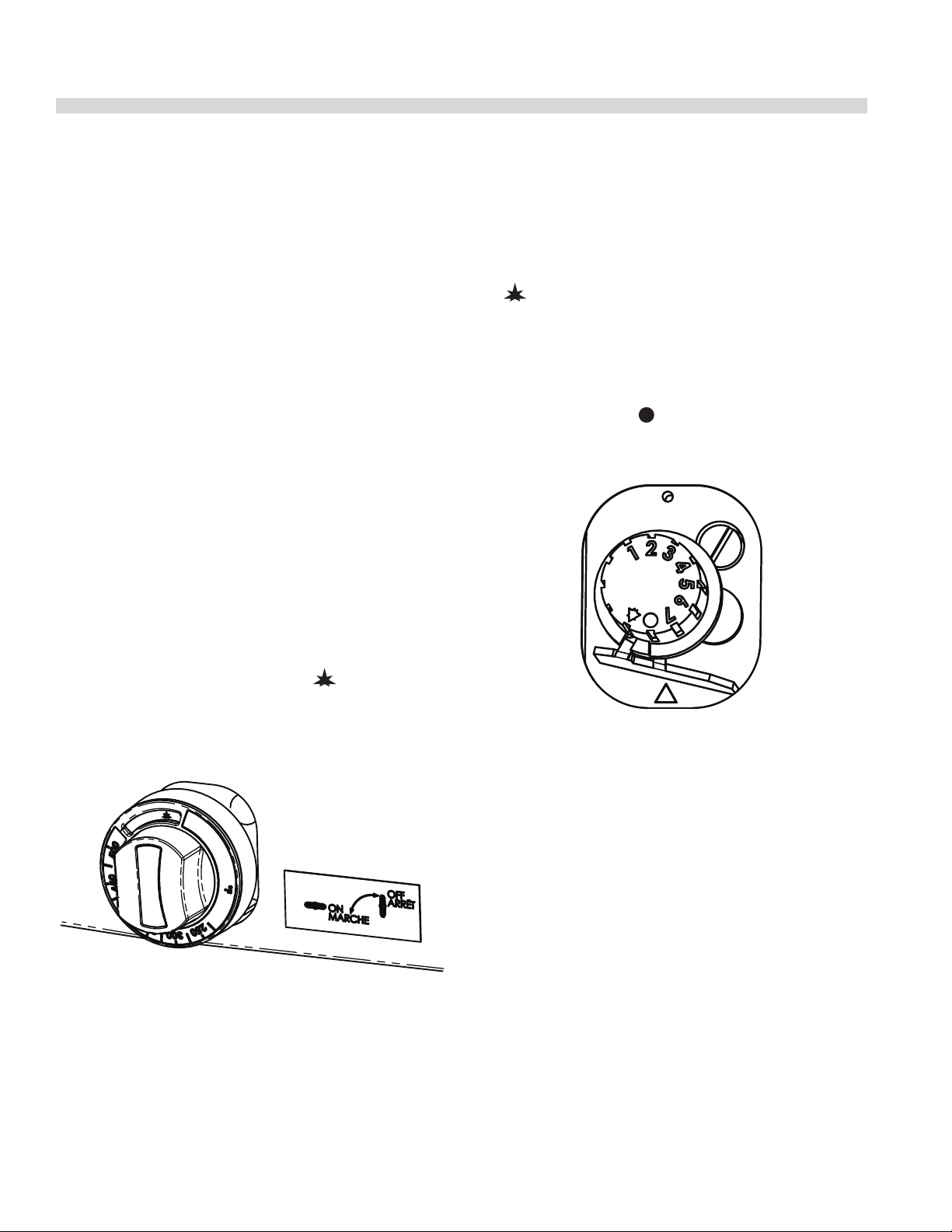
7. To shut down main burner turn control knob (gure 1) to
“ ” position.
Shut Down
If pilot shut down is required loosen the set screw on the
knob and remove the outer temperature thermostat knob
by carefully pulling it o. Then push in and turn the inner
control knob (gure 2) to position. The system will
disengage within 60 seconds.
Figure 2
1. Lower front kick panel below oven door, raise oven
hearth bottom for easy access to oven pilot.
2. Turn oven control knob (gure 1) to “ ” position and
then push in to engage the ow of gas through the safety
device to the pilot.
Figure 1
3. While holding knob in, light pilot with a match/BBQ
lighter or use the spark ignition (if provided) to spark
ignite pilot.
4. Continue to hold knob in for 15 seconds after ignition,
then release. Pilot should remain lit.
Convection Ovens
The forced air range oven consists of a food preparation
chamber completely sealed from the combustion area.
This eliminates the possibility of contamination from ue
products and permits an ecient method of circulating the
heated air within the cooking chamber.
During the cooking process in a conventional oven, a vapor
barrier and a layer of “cool” air covers the exposed area of
the product. In a forced air oven, the fan pushes the heated
air over and around the product, sweeping away the vapor
barrier and cool air, permitting faster heat penetration. This
action permits the use of lower temperatures and shorter
cooking times.
The rule of thumb for determining the cooking temperature
is to reduce the set temperature by approximately
80°F, (28°C), from that which you would set in a conventional
oven. The product should be checked at a point midway in
the time required in a conventional oven.
Part # 4523104 Rev 3 (03/04/10)Page 10
 Loading...