

Garland G24 SERIES, G24-24GFSD, G24-36GFSD, G24-48GFSD, G24-60GFSD Installation And Service Manual
...
INSTALLATION
OPERATION AND
SERVICE MANUAL
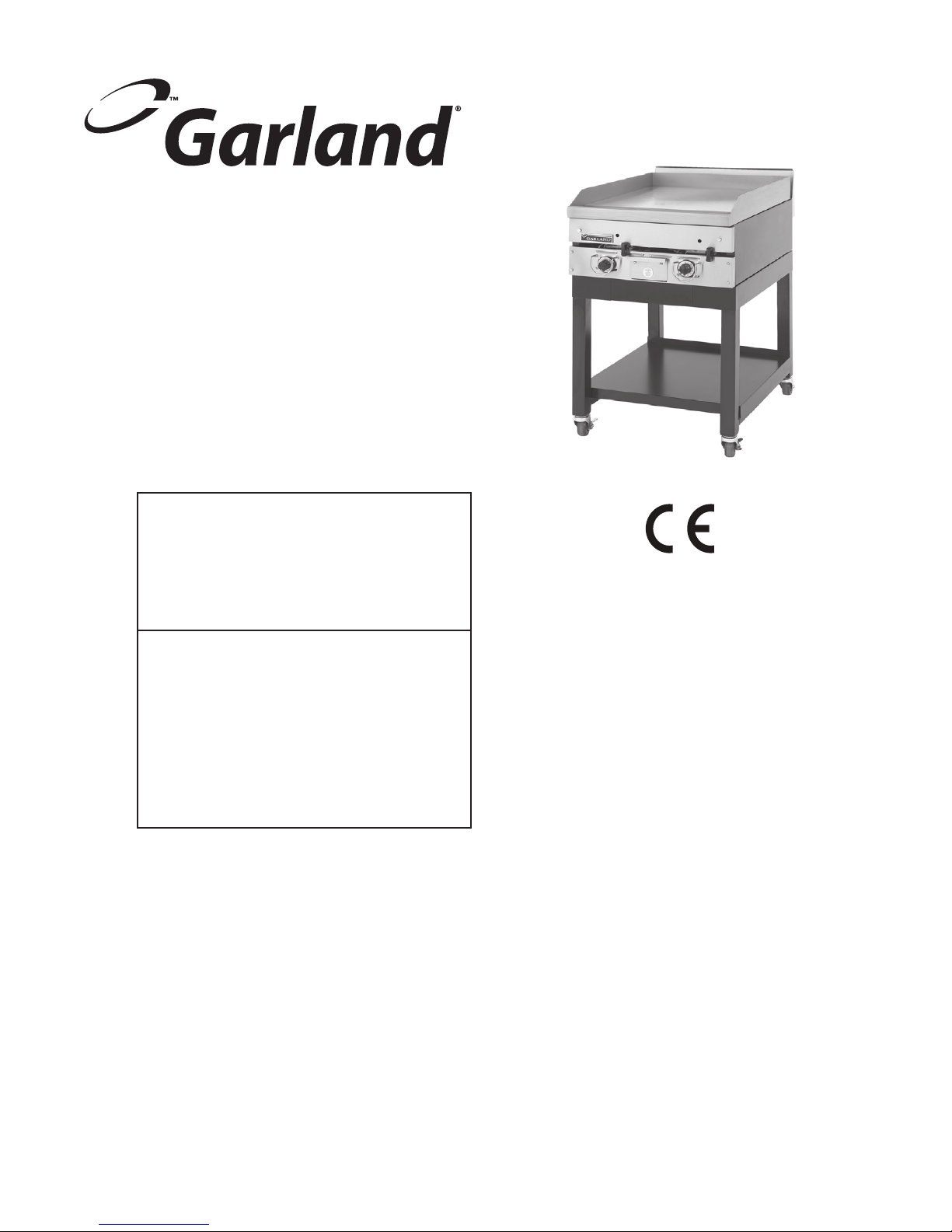
G24 SERIES
GAS-OPERATED
COUNTER GRIDDLE
FOR YOUR SAFETY:
DO NOT STORE OR USE GASOLINE
OR OTHER FLAMMABLE VAPORS OR
LIQUIDS IN THE VICINITY OF
THIS OR ANY OTHER
APPLIANCE
WARNING:
IMPROPER INSTALLATION, ADJUSTMENT,
ALTERATION, SERVICE OR MAINTENANCE
CAN CAUSE PROPERTY DAMAGE, INJURY,
OR DEATH. READ THE INSTALLATION,
OPERATING AND MAINTENANCE
INSTRUCTIONS THOROUGHLY
BEFORE INSTALLING OR
SERVICING THIS EQUIPMENT
PLEASE READ ALL SECTIONS OF THIS MANUAL
AND RETAIN FOR FUTURE REFERENCE.
THIS PRODUCT HAS BEEN CERTIFIED AS
COMMERCIAL COOKING EQUIPMENT AND
MUST BE INSTALLED BY PROFESSIONAL
PERSONNEL AS SPECIFIED.
For Your Safety:
Post in a prominent location, instructions to be
followed in the event the user smells gas. This
information shall be obtained by consulting
your local gas supplier.
Users are cautioned that maintenance and repairs must be performed by a Garland authorized service agent
using genuine Garland replacement parts. Garland will have no obligation with respect to any product that has been
improperly installed, adjusted, operated or not maintained in accordance with national and local codes or installation
instructions provided with the product, or any product that has its serial number defaced, obliterated or removed,
or which has been modified or repaired using unauthorized parts or by unauthorized service agents.
For a list of authorized service agents, please refer to the Garland web site at http://www.garland-group.com.
The information contained herein, (including design and parts specifications), may be superseded and is subject
to change without notice.
GARLAND COMMERCIAL INDUSTRIES
185 East South Street
Freeland, Pennsylvania 18224
Phone: (570) 636-1000
Fax: (570) 636-3903
Part # 4521357 (12/07) © 2006 Garland Commercial Industries, Inc.
Part # 4521357 (12/07) Page 1
GARLAND COMMERCIAL RANGES, LTD.
1177 Kamato Road, Mississauga, Ontario L4W 1X4
CANADA
Phone: 905-624-0260
Fax: 905-624-5669
Enodis UK LTD.
Swallow eld Way, Hayes, Middlesex UB3 1DQ ENGLAND
Telephone: 081-561-0433
Fax: 081-848-0041

IMPORTANT INFORMATION
WARNING:
This product contains chemicals known to the state of california to cause cancer and/or birth defects
or other reproductive harm. Installation and servicing of this product could expose you to airborne
particles of glass wool/ceramic fibers. Inhalation of airborne particles of glass wool/ceramic fibers
is known to the state of california to cause cancer. Operation of this product could expose you to
carbon monoxide if not adjusted properly. Inhalation of carbon monoxide is known to the state of
california to cause birth defects or other reproductive harm.
Keep appliance area free and clear of combustibles.
Part # 4521357 (12/07)Page 2

TABLE OF CONTENTS
Important Information . . . . . . . . . . . . . . . . . 2
Model Designation. . . . . . . . . . . . . . . . . . . . . 4
Technical Specications . . . . . . . . . . . . . . . . 5
Table A: Exterior Dimensions . . . . . . . . . . . . . . . . . 5
Table B: Gas Flow Rate Per Model . . . . . . . . . . . . . 5
Table C: Nominal Heat Input (Net) Per Model . . 5
Table D: Injector Size . . . . . . . . . . . . . . . . . . . . . . . . . 6
Table E: Setting Pressure For “Min”
Tap Position . . . . . . . . . . . . . . . . . . . . . . . . . . . . . . . . . 6
Table F: Aeration Shutter Setting /
Pilot Flame Length . . . . . . . . . . . . . . . . . . . . . . . . . . 6
Table G: Australia Only – Injector Size,
NGC And Pressure . . . . . . . . . . . . . . . . . . . . . . . . . . . 6
Introduction. . . . . . . . . . . . . . . . . . . . . . . . . . . 7
Uncrating . . . . . . . . . . . . . . . . . . . . . . . . . . . . . . . . . . . . 7
Product Application . . . . . . . . . . . . . . . . . . . . . . . . . . 7
Optional Extras . . . . . . . . . . . . . . . . . . . . . . . . . . . . . . 7
Rating Plate . . . . . . . . . . . . . . . . . . . . . . . . . . . . . . . . . . 7
Commissioning . . . . . . . . . . . . . . . . . . . . . . .10
Burner Adjustments . . . . . . . . . . . . . . . . . . . . . . . . . 10
Operation Instructions . . . . . . . . . . . . . . . . 11
Operating Controls . . . . . . . . . . . . . . . . . . . . . . . . . 11
Lighting The Griddle . . . . . . . . . . . . . . . . . . . . . . . . 11
Safety . . . . . . . . . . . . . . . . . . . . . . . . . . . . . . . . . . . . . . 11
Routine Maintenance & Cleaning . . . . . . 12
General Cleaning . . . . . . . . . . . . . . . . . . . . . . . . . . . 12
Painted Finishes. . . . . . . . . . . . . . . . . . . . . . . . . 12
Stainless Steel . . . . . . . . . . . . . . . . . . . . . . . . . . . 12
Griddle Seasoning . . . . . . . . . . . . . . . . . . . . . . . . . . 12
Griddle Cleaning . . . . . . . . . . . . . . . . . . . . . . . . . . . . 12
Maintenance & Servicing Instructions . . 13
Gas Taps . . . . . . . . . . . . . . . . . . . . . . . . . . . . . . . . . . . . 13
Main Burners - Cleaning . . . . . . . . . . . . . . . . . . . . . 13
Pilot Burners - Cleaning . . . . . . . . . . . . . . . . . . . . . 13
Miscellaneous . . . . . . . . . . . . . . . . . . . . . . . . . . . . . . 13
Installation . . . . . . . . . . . . . . . . . . . . . . . . . . . . 8
Statutory Regulations . . . . . . . . . . . . . . . . . . . . . . . . 8
Australia Specic Clause . . . . . . . . . . . . . . . . . . . . . . 8
Siting . . . . . . . . . . . . . . . . . . . . . . . . . . . . . . . . . . . . . . . . 8
Clearances . . . . . . . . . . . . . . . . . . . . . . . . . . . . . . . . . . . 8
Ventilation Air . . . . . . . . . . . . . . . . . . . . . . . . . . . . . . . 8
Replacement Of Parts . . . . . . . . . . . . . . . . . 13
Gas Taps . . . . . . . . . . . . . . . . . . . . . . . . . . . . . . . . . . . . 13
Pilot Burner/Thermocouple/Spark Electrode . 14
Piezo Ignitor . . . . . . . . . . . . . . . . . . . . . . . . . . . . . . . . 14
Conversion Instructions . . . . . . . . . . . . . . . 14
Fault Finding . . . . . . . . . . . . . . . . . . . . . . . . . 15
Gas Connection . . . . . . . . . . . . . . . . . . . . . . . . . . . . . . 8
Gas Supply . . . . . . . . . . . . . . . . . . . . . . . . . . . . . . . . . . 8
Installation Procedure . . . . . . . . . . . . . . . . . . . . . . . . 9
Leg Installation . . . . . . . . . . . . . . . . . . . . . . . . . . . . . . 9
Installation Of Counter Stands (Optional) . . . . . . 9
Part # 4521357 (12/07) Page 3
Safety Concerns . . . . . . . . . . . . . . . . . . . . . . 15
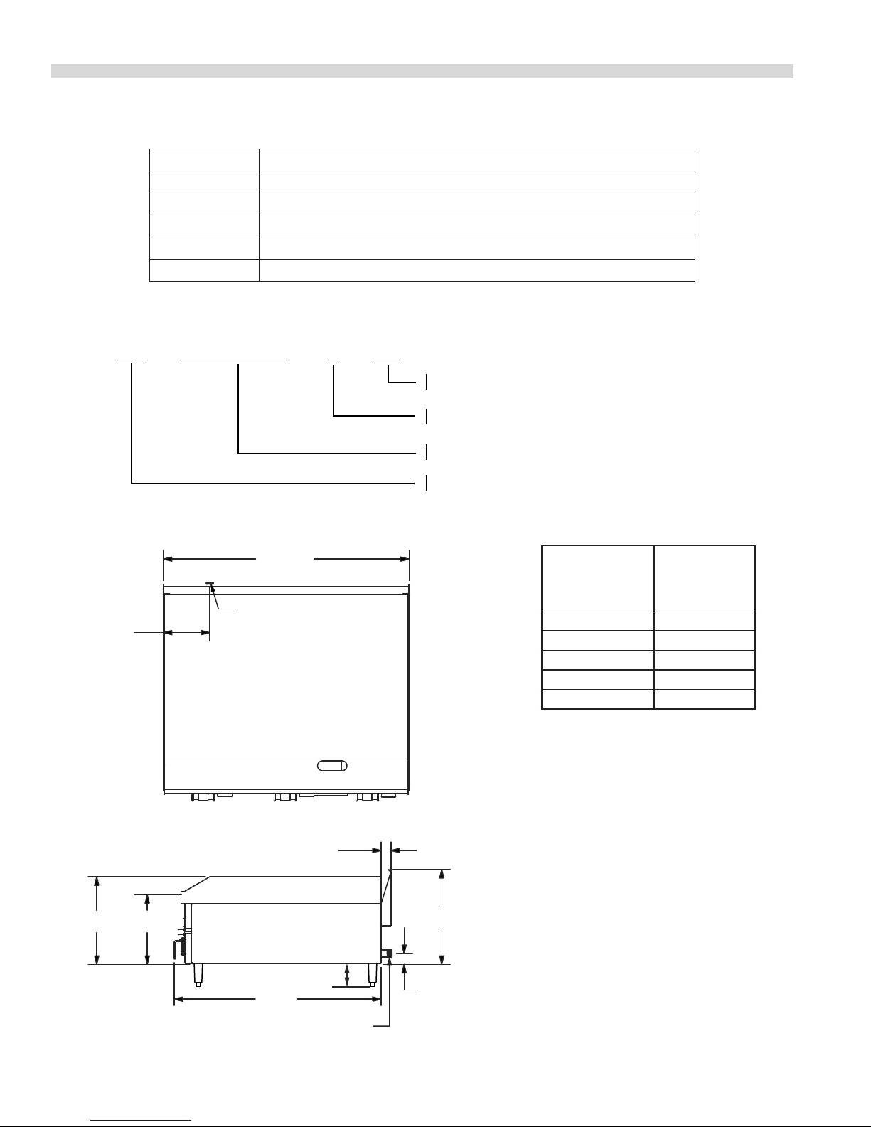
MODEL DESIGNATION
(327mm)
1" NPT GAS INLET
(G24-48,G24-60,G24-72)
12-7/8"
(38mm)
3/4" NPT INLET
(G24-24,G24-36)
1" NPT GAS INLET (G24-48,G24-60,G24-72)
3/4" NPT INLET (G24-24,G24-36)
*HEIGHT OF GRIDDLE PLATE
WIDTH
(38 mm)
13-7/8"
6-3/4"
(772mm)
1-1/2"
30-3/8"
(171mm)
(259mm)
(352 mm)
1-1/2"
10-1/4" *
4" (102mm)
SUFFIX DEFINITIONS:
G24 24, 36, 48, 60, 72 G FSD
FLAME SAFETY DEVICES FITTED
GAS GRIDDLE
NOMINAL WIDTH OF GRIDDLE IN INCHES
BASE MODEL NUMBER
MODEL DESCRIPTION
G24-24GFSD 610 mm wide x 324 mm high, heavy duty counter top griddle.
G24-36GFSD 914 mm wide x 324 mm high, heavy duty counter top griddle.
G24-48GFSD 1219 mm wide x 324 mm high, heavy duty counter top griddle.
G24-60GFSD 1524 mm wide x 324 mm high, heavy duty counter top griddle.
G24-72GFSD 1829 mm wide x 324 mm high, heavy duty counter top griddle.
Model Width
G24-24GFSD 24” (610mm)
G24-36GFSD 36” (914mm)
G24-48GFSD 48” (1219mm)
G24-60GFSD 60” (1524mm)
G24-72GFSD 72” (1829mm)
Part # 4521357 (12/07)Page 4
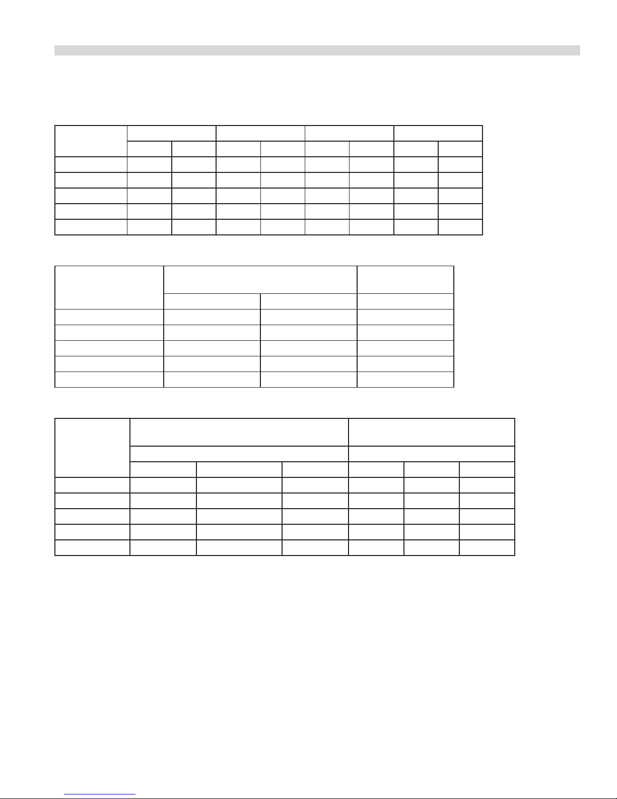
TECHNICAL SPECIFICATIONS
Table A: Exterior Dimensions
MODELS
G24-24GFSD 324 12.75 610 24 781 30.75 109 240
G24-36GFSD 324 12.75 914 36 781 30.75 159 350
G24-48GFSD 324 12.75 1219 48 781 30.75 227 500
G24-60GFSD 324 12.75 1524 60 781 30.75 272 600
G24-72GFSD 324 12.75 1829 72 781 30.75 318 700
HEIGHT WIDTH DEPTH WEIGHT
mm Ins mm Ins mm Ins Kg Lb.
Table B: Gas Flow Rate Per Model
NATURAL GAS
MODELS
G20 @ 20mbar G25 @ 25 mbar G31 @ 37/50 mbar
G24-24GFSD 1.9 1.97 1.4
G24-36GFSD 2.86 2.96 2.09
G24-48GFSD 3.81 3.94 2.8
G24-60GFSD 4.76 4.92 3.49
G24-72GFSD 5.71 5.91 4.19
( m3/h )
PROPANE GAS
(kg/h )
Table C: Nominal Heat Input (Net) Per Model
(G20 @ 20 mbar ) NATURAL GAS
MODELS
G24-24GFSD 18 / 16 61,400/54,600 64.8/57.6 18 61,400 64.8
G24-36GFSD 27 / 24 92,150/81,900 97.2/86.4 27 92,150 97.2
G24-48GFSD 36 / 32 122,850/109,200 129.6/115.2 36 122,850 129.6
G24-60GFSD 45 / 40 153,500/136,500 161.9/144.0 45 153,500 161.9
G24-72GFSD 54 / 48 184,250/163,750 194.4/172.7 54 184,250 194.4
( G25 @ 25 mbar ) NATURAL GAS
Nominal Heat Input (G20 / G25) Nominal Heat Input
kW BTU/HR MJ/HR kW BTU/HR MJ/HR
(G31 @ 37/50 mbar ) PROPANE
Part # 4521357 (12/07) Page 5
 Loading...