

Page 1

INSTALLATION OPERATION
AND SERVICE MANUAL
G2000 SERIES GAS BAKE AND
ROAST DECK OVENS
FOR YOUR SAFETY:
DO NOT STORE OR USE GASOLINE
OR OTHER FLAMMABLE VAPORS OR
LIQUIDS IN THE VICINITY OF
THIS OR ANY OTHER
APPLIANCE
WARNING:
IMPROPER INSTALLATION, ADJUSTMENT,
ALTERATION, SERVICE OR MAINTENANCE
CAN CAUSE PROPERTY DAMAGE, INJURY,
OR DEATH. READ THE INSTALLATION,
OPERATING AND MAINTENANCE
INSTRUCTIONS THOROUGHLY
BEFORE INSTALLING OR
SERVICING THIS EQUIPMENT
AND RETAIN FOR FUTURE REFERENCE.
THIS PRODUCT HAS BEEN CERTIFIED AS
COMMERCIAL COOKING EQUIPMENT AND
MUST BE INSTALLED BY PROFESSIONAL
PERSONNEL AS SPECIFIED.
IN THE COMMONWEALTH OF MASSACHUSETTS
THIS PRODUCT MUST BE INSTALLED BY A
LICENSED PLUMBER OR GAS FITTER. APPROVAL
NUMBER: G-1-07-05-28
For Your Safety:
Post in a prominent location, instructions to be
followed in the event the user smells gas. This
information shall be obtained by consulting
your local gas supplier.
Users are cautioned that maintenance and repairs must be performed by a Garland authorized service agent
using genuine Garland replacement parts. Garland will have no obligation with respect to any product that has been
improperly installed, adjusted, operated or not maintained in accordance with national and local codes or installation
instructions provided with the product, or any product that has its serial number defaced, obliterated or removed,
or which has been modified or repaired using unauthorized parts or by unauthorized service agents.
For a list of authorized service agents, please refer to the Garland web site at http://www.garland-group.com.
The information contained herein, (including design and parts specifications), may be superseded and is subject
to change without notice.
PLEASE READ ALL SECTIONS OF THIS MANUAL
GARLAND COMMERCIAL INDUSTRIES
185 East South Street
Freeland, Pennsylvania 18224
Phone: (570) 636-1000
Fax: (570) 636-3903
Part # P125 Rev 1 (05/20/08) © 2005 Garland Commercial Industries, Inc.
Part # P125 Rev 1 (05/20/08) Page 1
GARLAND COMMERCIAL RANGES, LTD.
1177 Kamato Road, Mississauga, Ontario L4W 1X4
CANADA
Phone: 905-624-0260
Fax: 905-624-5669
Enodis UK LTD.
Swallow eld Way, Hayes, Middlesex UB3 1DQ ENGLAND
Telephone: 081-561-0433
Fax: 081-848-0041
Page 2

IMPORTANT INFORMATION
WARNING:
This product contains chemicals known to the state of california to cause cancer and/or birth defects
or other reproductive harm. Installation and servicing of this product could expose you to airborne
particles of glass wool/ceramic fibers. Inhalation of airborne particles of glass wool/ceramic fibers
is known to the state of california to cause cancer. Operation of this product could expose you to
carbon monoxide if not adjusted properly. Inhalation of carbon monoxide is known to the state of
california to cause birth defects or other reproductive harm.
Keep appliance area free and clear of combustibles.
Part # P125 Rev 1 (05/20/08)Page 2
Page 3

TABLE OF CONTENTS
Important Information . . . . . . . . . . . . . . . . . 2
Dimensions And Specications,
G2000 Series . . . . . . . . . . . . . . . . . . . . . . . . . . 4
OVEN SPECIFICATIONS . . . . . . . . . . . . . . . . . 5
General . . . . . . . . . . . . . . . . . . . . . . . . . . . . . . . . . . . . . . 5
INTRODUCTION. . . . . . . . . . . . . . . . . . . . . . . . 5
Garland Variety Ovens . . . . . . . . . . . . . . . . . . . . . . . 5
INSTALLATION . . . . . . . . . . . . . . . . . . . . . . . . . 6
Pre-Installation Instructions . . . . . . . . . . . . . . . . . . 6
Rating Plate . . . . . . . . . . . . . . . . . . . . . . . . . . . . . . . . . . 6
Location of the Oven . . . . . . . . . . . . . . . . . . . . . . . . . 6
Clearances . . . . . . . . . . . . . . . . . . . . . . . . . . . . . . . . . . . 6
Legs . . . . . . . . . . . . . . . . . . . . . . . . . . . . . . . . . . . . . . . . . 7
Assembly of Two-Section Oven . . . . . . . . . . . . . . . 7
Installation of Oven Vent . . . . . . . . . . . . . . . . . . . . . 7
Top Trim Installation . . . . . . . . . . . . . . . . . . . . . . . . . 8
Ovens with Optional Light Feature . . . . . . . . . . . . 8
Gas Connection-Single & Multiple Ovens . . . . . . 8
Operation . . . . . . . . . . . . . . . . . . . . . . . . . . . . 10
Burn O – Deck Curing . . . . . . . . . . . . . . . . . . . . . . 10
User Guide – Timetable for Roasting . . . . . . . . . 11
User Guide – Timetable for Baking . . . . . . . . . . . 13
Maintenance . . . . . . . . . . . . . . . . . . . . . . . . .14
Painted Finishes . . . . . . . . . . . . . . . . . . . . . . . . . . . .14
Stainless Steel . . . . . . . . . . . . . . . . . . . . . . . . . . . . . .14
Oven Interior . . . . . . . . . . . . . . . . . . . . . . . . . . . . . . . 14
Cleaning of Oven Hearth . . . . . . . . . . . . . . . . . . . .14
Adjustments. . . . . . . . . . . . . . . . . . . . . . . . . . 15
Oven Door . . . . . . . . . . . . . . . . . . . . . . . . . . . . . . . . .15
Thermocouple Replacement . . . . . . . . . . . . . . . . 15
Magnet Assembly & Thermocouple Test . . . . . 15
Oven Burners . . . . . . . . . . . . . . . . . . . . . . . . . . . . . . .16
Thermostat Operation . . . . . . . . . . . . . . . . . . . . . . 16
Instructions for FDO Heavy Duty Control . . . . . 17
By-Pass Adjustment . . . . . . . . . . . . . . . . . . . . . . . . . 17
Recalibration . . . . . . . . . . . . . . . . . . . . . . . . . . . . . . . 17
Installation Of Oven Heat Deectors,
Corderite/Steel Hearths &
Inner Oven Linings . . . . . . . . . . . . . . . . . . . . . . . . . . . 9
Ventilation and Air Supply . . . . . . . . . . . . . . . . . . . . 9
Installation of a Direct Flue . . . . . . . . . . . . . . . . . . . 9
Part # P125 Rev 1 (05/20/08) Page 3
Page 4
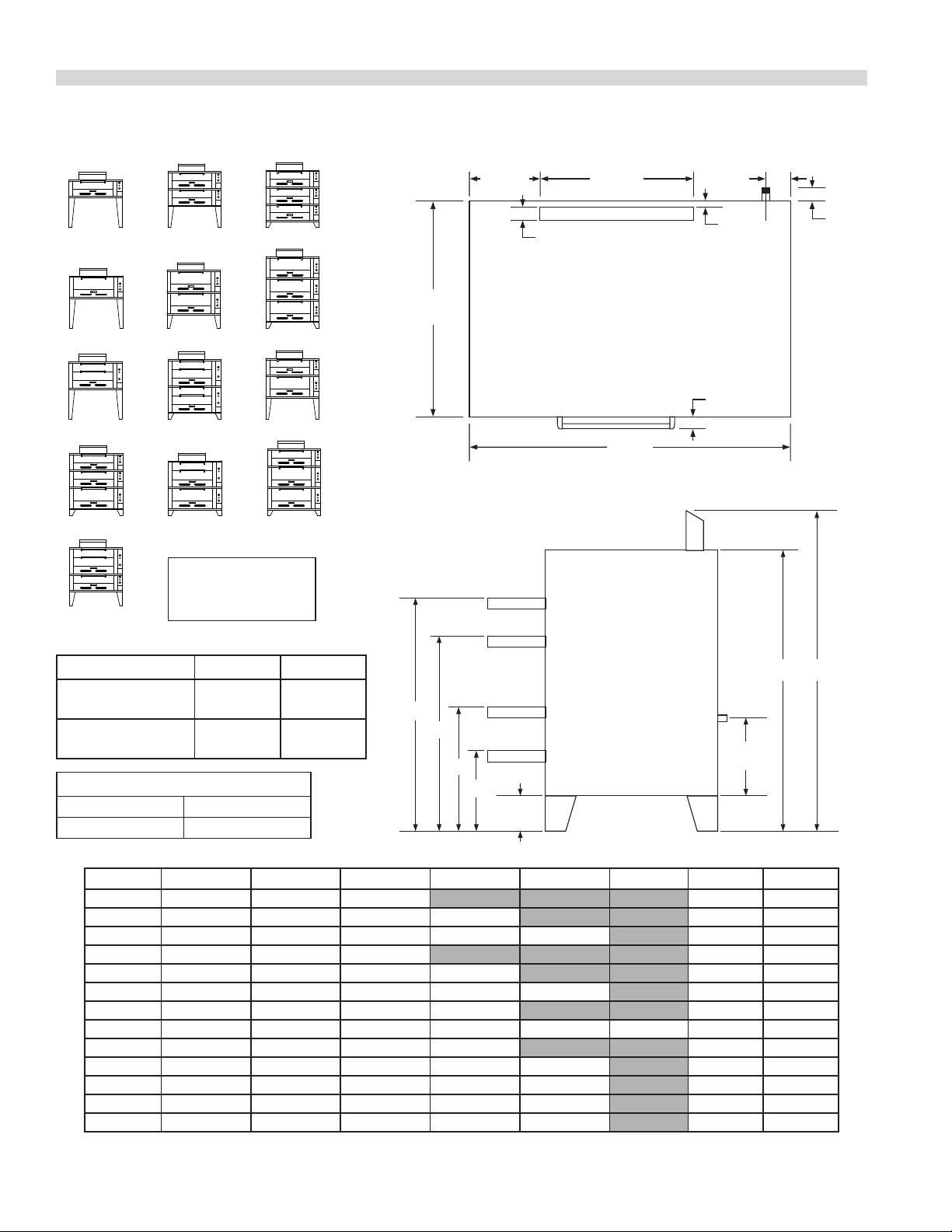
DIMENSIONS AND SPECIFICATIONS, G2000 SERIES
17"
(432mm)
G
C
D
E
F
B
A
3/4" NPT
GAS INLET
55-1/4"
(1416mm)
10-5/8"
(280mm)
2"
(51mm)
1"
(25mm)
2-1/4"
(57mm)
3"
(76mm)
27-7/8"
(708mm)
2"
(51mm)
38-1/4"
(972mm)
G2121-71
G2073
7B
7B
7B
12R
7B
G2121-771
G2071
7B
12R
12R
T7B
T7B
12R
G2122
G2771
G2072
7B
7B
12R
12R
T7B
7B
7B
T7B
T7B
12R
12R
12R
G2123
G2122-71
G2772
G2071-771
G2121-72
G2121
12R
7B
7B
12R
7B = 7" Bake
T7B = Twin 7" Bake
12R = 12" Roast
All Models Natural Propane
Manifold
Operating Pressure
Minimum
Supply Pressure
Clearances To Combustible Wall
Sides Back
1” (25mm) 6” (152mm)
MODEL A B C D E F G Total BTU
G2071
G2072
G2073
G2121
G2122
G2123
G2771
G2772
G2121-71
G2121-72
G2121-771
G2122-71
G2071-771
5.5" WC
(13.7 Mbar)
7.,0" WC
(17.4 Mbar)
50" (1270mm) 58" (1473mm) 401⁄2" (1664mm) 31" (787mm) 40,000
581⁄2" (1270mm) 661⁄2" (1689mm) 311⁄2" (800mm) 49" (1283mm) 22" (559mm) 80,000
60" (1524mm) 68" (1727mm) 151⁄2" (394mm) 33" (838mm) 501⁄2" (1283mm) 6" (152mm) 120,000
55" (1397mm) 63" (1600mm) 401⁄2" (1664mm) 31" (787mm) 40,000
601⁄2" (1537mm) 681⁄2" (1740mm) 231⁄2" (597mm) 46" (1168mm) 14" (356mm) 80,000
75" (1905mm) 83" (2018mm) 151⁄2" (394mm) 38" (965mm) 601⁄2" (1537mm) 6" (152mm) 120,000
60" (1524mm) 68" (1727mm) 401⁄2" (1664mm) 501⁄2" (1283mm) 31" (787mm) 50,000
621⁄2" (1587mm) 701⁄2" (1791mm) 151⁄2" (394mm) 251⁄2" (648mm) 43" (1092mm) 53" (1346mm) 6" (152mm) 100,000
631⁄2" (1613mm) 711⁄2" (1816mm) 311⁄2" (800mm) 54" (1372mm) 22" (559mm) 80,000
65" (1651mm) 73" (1854mm) 151⁄2" (394mm) 38" (965mm) 551⁄2" (1410mm) 6" (152mm) 120,000
571⁄2" (1460mm) 651⁄2" (1664mm) 151⁄2" (394mm) 38" (965mm) 48" (1219mm) 6" (152mm) 90,000
70" (1778mm) 78" (1981mm) 151⁄2" (394mm) 38" (965mm) 601⁄2" (1537mm) 6" (152mm) 120,000
601⁄2" (1537mm) 681⁄2" (1664mm) 231⁄2" (597mm) 41" (1041mm) 51" (1295mm) 14" (356mm)
10.0" WC
(24.9 Mbar
11.0" WC
(27.4 Mbar)
Part # P125 Rev 1 (05/20/08)Page 4
90,000
Page 5

OVEN SPECIFICATIONS
General
Construction:
Ovens are of the sectional type with each section operating
independently. Sectional type with each section operating
independently. Sectional design makes it easy to add
additional sections as required. Heavy duty modular
construction minimizes the use of hard to clean screws and
bolts on the exterior of the oven. Cleaning is easier and more
complete. Sections are supported on heavy steel legs, which
are easily changed as sections are added. Oven legs are
standard equipment.
Bake Section:
Bake section interior is 42” x 32” x 7” each section. The ¾”
corderite deck is provided as standard equipment. A 12
gauge steel hearth may be substituted if specied before
placing order.
General Purpose Section:
Two compartments 42” x 32” x 7” each section. Each provided
with its own deck and door. Standard deck is ¾” thick
corderite. A 12 gauge hearth may be substituted if specied
before placing order.
Roast Sections:
The 12” roast interior is 42” x 32” x 12”. Interior of the 16”
sections is 42” x 32” x 16”. A 12 gauge steel hearth is provided
as standard for both 12” gauge steel hearth is provided as
standard for both 12” and 16” sections. A corderite deck is
available as an optional extra.
Burners:
Each oven is heated by two “U” shaped lance ported burners
ring directly on heavy steel tread plate between the burners
and the deck. In each oven section, a heavy duty throttling/
snap action gas thermostat controls burners to provide a
150º to 500º Fahrenheit temperature range aording low
temperature holding feature. Each section is further provide
with an independent ON/OFF gas valve and 100% safety
pilot system.
Venting:
Flue deector is provided to meet ventilation system
requirements. Internal ues connect for stacking.
Oven Door:
Oven door is engineered with precise balance and
exceptional durability. Door opens to full width of oven
cavity and to exact level of horizontal oven deck for
unobstructed loading. Door will support tin excess of 250
pounds of load.
INTRODUCTION
Garland Variety Ovens
The dependable line of Garland Variety Heavy Duty Bake and
Roast Ovens are designed for use where quality foods are
prepared in mass quantity. These ovens are ideal for hotels,
hospital, schools, larger cafeterias, dining rooms and all other
high production operations.
Basic Variety Oven sections are designed for stacking to
provide an innite choice of bake and roast combinations.
Independently operated oven sections with separate
controls, aord the advantage of cooking a variety of
products at dierence temperatures at the same time.
Part # P125 Rev 1 (05/20/08) Page 5
GARLAND’S new Variety Oven line was designed to give
years of dependable service. Engineering excellence assures
customers of quality construction and products that perform
well. This addition to the GARLAND family of commercial
cooking products is testimony to the dedicated eorts of
our employees, who have pride in their workmanship and
therefore, build better products that reect this spirit.
Page 6

INTRODUCTION Continued
Rating Plate
When corresponding with the factory or your local
authorized factory service center regarding service problems
or replacement parts, be sure to refer to the particular unit
by the correct model number (including the prex and sux
letters and numbers) and the warranty serial number. The
rating plate axed to the unit contains this information.
We suggest installation, maintenance and repairs should be
performed by your local authorized service agency listed in
your information manual pamphlet.
In the event you have any questions concerning the
installation, use, care or service of the product, write or call
our Product Service Department.
This product must be installed by professional personnel as
specied. Garland/U.S. Range products are not approved or
authorized for home or residential use, but are intended for
commercial applications only. Garland / U.S. Range will not
provide service, warranty, maintenance or support of any
kind other than in commercial applications.
Location of the Oven
Appliances shall be installed in a location in which the
facilities for ventilation permit satisfactory combustion of gas
and proper venting. Appliances shall be located so as not to
interfere with proper circulation of air within the conned
space. When buildings are so tight that normal inltration
does not provide the necessary air, outside air shall be
introduced.
Clearances
NOTE: Unit must be installed with no less than
6 inches (152mm) clearance from combustible construction
at both sides and rear. Installation to non-combustible
construction is (0”) clearance at both sides and rear. The unit
suitable for installation on combustible oors.
INSTALLATION
Pre-Installation Instructions
The importance of proper installation of commercial
gas cooking equipment cannot be over stressed. Proper
performance of the equipment is dependent, in great part,
on the compliance of the installation with the manufacturer’s
specications. The installation and connections must comply
with local codes, or in the absence of local codes, with
CAN/CGA-B149 installation code or with the National Fuel
Gas code, ANSI Z 223.1/NFPA No. 54 – latest edition.
All burner adjustments and setting shall be made by a
qualied gas technician.
A. The type of gas for which the unit is equipped is stamp on
the date plate located behind lower front panel. Connect
a unit stamped “NAT” only to natural gas; connect a unit
stamped “PRO” only to propane gas.
B. If it is a new installation, have gas authorities check meter
size and piping to assure that the unit is supplied with
sucient amount of gas pressure required to operate the
unit.
C. If it is additional or replacement equipment, have gas
authorities check pressure to make certain that existing
meter and piping will supply fuel at the unit with not
more than 1/2” water column pressure drop.
Part # P125 Rev 1 (05/20/08)Page 6
Page 7

Bottom Flue
Cover Patch
INSTALLATION Continued
D. Obtain a pressure regulator to deliver gas at the pressure
shown on the rating plate. This unit is supplied with a
pressure regulator.
NOTE: When checking pressure be sure that all other
equipment on the same gas line is on. A pressure regulator
is supplied with GARLAND equipped. Set regulator to deliver
gas at pressure shown on rating plate. Installation must
conform with the national Fuel Gas Code ANSI Z223.1-Latest
Edition/NFPA No. 54-Latest Edition and/or local code to
assure safe and ecient operation.
NOTE: In Canada, the installation shall be in accordance
with CAN/CGA-B149.1 NATURAL GAS INSTALLATION CODE
or CAN/CGA-B149.2 PROPANE GAS INSTALLATION CODE and
local codes where applicable.
NOTE: The appliance and its individual shut-o (supplied by
others) must be disconnected from the gas supply piping
system during any pressure testing of that system at test
pressures in excess of 1/2 PSI (3.45kPa).
The appliance must be isolated from the gas supply piping
by closing its individual manual shut-o (supplied by others)
during any pressure testing of the gas supply piping system
at test pressures equal to or less than ½ PSI (3.45 kPa).
NOTE: Adequate clearance must be provided for servicing
and proper operation.
Legs
Assembly of Two-Section Oven
Before raising the upper section into its proper position,
check at the rear centre of the underside of the upper section
(as per drawing). The rectangular ue opening should be
open. If the ue opening is covered, remove the “Bottom Flue
cover Patch” and discard.
Be sure that the top trim cap (stainless steel angle iron square
frame) is not installed on the lower or middle ovens. Place
2 x 4’s on the top of the lower or middle ovens. Place
2 x 4’s on the top of the lower oven section – about 6” in from
each side, running front to back. Raise the top section and
position it on the 2 x 4’s so that the front, rear and sides of the
top section line up with the lower section. The internal upper
ue will telescope over the internal lower ue.
Raise the front of the oven. Position the legs inside the front
corners of the angle from frame. Start each bolt, threading
them into the weld nuts on the angle base frame. Four (4)
bolts and four (4) washers must be used to secure each leg in
place. Tighten the bolts evenly and securely. Raise and block
the rear of the oven and fasten the rear legs as above.
Part # P125 Rev 1 (05/20/08) Page 7
The upper oven section bottom frame will telescope or
capture the bottom unit. It is not necessary to bolt the
section together.
Installation of Oven Vent
1. The most ecient system for ventilating this oven is
a properly designed hood. This hood should extend
6 inches beyond the front and sides of the oven and
the back, unless oven is against a re resistive wall. The
design of the hood should be such that it will not pull the
heat too rapidly out of the oven through the ue.
Page 8

INSTALLATION Continued
FLUE DEFLECTOR
FIGURE 1
BAROMETRIC
DAMPER
DRAFT HOOD
FIGURE 2
The ue deector provided (Fig. 1) should be installed
to prevent this situation from occurring. Set the ue
deector in place over the anges of the internal ue. The
sloped opening of the ue deector will be to the front.
Fasten the side anges of the ue deector by means of
the sheet metal screws provided.
2. If the oven must be connected to a direct ue, this ue
should rise 10 feet above the roof of the building in
which the oven is installed, or 10 feet above any portion
of a building within a horizontal distance of 10 feet. The
draft hood provided must be installed. In addition, it is
necessary that barometric draft control (available from
Garland) be installed. (See Fig. 2)
The draft hood should be positioned with its vertical
bottom opening over the vertical anges of the oven
ue. The anges of the draft hood should be to the sides
and front. Fasten the draft hood to the oven by means of
sheet metal screws through the holes on each side ange
at the bottom of the draft hood.
The barometric damper must be installed to conform
with the applicable instructions packed with the
barometric damper. The relief opening of the barometric
damper should be located so that it is not obstructed by
any part of the oven or adjacent constructions.
The barometric damper should be installed as close to
the draft hood as possible, while conforming to code
requirements.
Under no circumstances should ue pipe with less than
a 6 inch diameter be installed between the oven and the
chimney termination.
If more than one appliance is connected to a single
vent, the vent shall be sized in accordance with sound
engineering principles.
Top Trim Installation
The front of the top trim is formed as a channel. Open the
upper oven door. Hold the top trim with the rear raised
and slide its lower ange into position in the oven opening
between the right and the left front columns. Lower the top
trim into position over the oven top. The top trim does not
require that it be bolted or fastened into position.
Ovens with Optional Light Feature
Important: This appliance must be electrically grounded in
accordance with local codes, or in the absence of local codes,
the Canadian Electrical Code C22.1 or with the National
electrical code ANSI/NFPA No. 70 (latest edition whichever is
applicable.
Warning – Electric Grounding Instructions
This appliance is equipped with a three prong (grounding)
plug for your protection against shock hazard and must be
plugged into a properly grounded three prong receptacle.
Do not cut or remove the grounding prong from this plug.
A wiring diagram is attached to the back of the unit.
Gas Connection-Single & Multiple Ovens
Single Oven
Install the pressure regulator (supplied) with the outlet
(arrowhead) connected to the tail pipe. The ¾” N.P.T. inlet of
the pressure regulator must be considered in piping the gas
supply. Each group of ovens should be supplied (by others)
with an in-line manual shut o valve.
Part # P125 Rev 1 (05/20/08)Page 8
Page 9

INSTALLATION Continued
PRESSURE
REGULATOR
GAS
SUPPLY
STACKING PIPE KIT
FOR COMBINATION OVEN
DIAGRAM "A"
INNER OVEN LINING
RIGHT AND LEFT
DECK SPACER
RIGHT, REAR AND LEFT
DECK
HEAT DEFLECTOR
HEAT DEFLECTOR PAN (2)
DECK FRAME (Ref.)
DIAGRAM "B"
Each stack of oven sections may be piped individually as
described above. Each stack should be provided with its own
manual gas shut o valve as described. If the ovens are to be
piped using all of the materials provide, refer to diagram “A”.
Multiple Ovens
If the ovens are to be stacked, they may be piped as shown
in the diagram “A”. Again, as stated above, a readily accessible
gas shut o valve of an approved type should be installed in
the supply line.
The steel hearth is designed as a one-piece welded assembly
and will pass through the oven door opening. The rear of the
steel hearth assembly rests on the heat deectors inside the
rear angle support. Centre the steel hearth assembly within
the oven. Install the aluminized inner oven linings provided,
as shown in Diagram “B”.
IMPORTANT: All gas burners and pilots need sucient air to
operate and large objects should not be placed in front of
this appliance which would obstruct the air ow through the
front.
Ventilation and Air Supply
Installation Of Oven Heat Deectors,
Corderite/Steel Hearths &
Inner Oven Linings
All models require that two part oven heat deectors (heavy
gauge diamond plate) and two heat deector pans (in oven
with corderite deck material) or one heat deector pan (in
oven with steel deck), be installed above the oven burners
to give even heat throughout the oven. Install the heat
deector pan(s) in the centre of the oven deck frame. Install
the heat deectors on top of the heat deector pans, with
the rough side up.
Both deectors should be brought together to make the
centre seam as tight as possible.
The corderite hearth assembly consists of two sections
installed within deck spacers, as shown in Diagram “B”. Install
the two (2) aluminized inner oven linings in the front and
rear channels by rst placing the rear of each in each rear
channel. Then raise the front of each aluminized inner oven
linings over and down into the front channels.
Part # P125 Rev 1 (05/20/08) Page 9
Proper ventilation is highly important for good operation.
The ideal method of venting a gas deck oven is through the
use of a properly designed canopy which should extend 6”
beyond all sides of the appliance and 6’6” from the oor.
A strong exhaust fan will create a vacuum in the room. For an
exhaust system vent to work properly, replacement air must
enter the room in which the vent is located. For proper air
balance, contact your local H.V.A.C. contractor.
Installation of a Direct Flue
When the installation of a canopy type exhaust hood is
impossible, the oven may be direct vented. Before direct
venting check your local codes on ventilation.
If the unit is to be connected directly to a direct ue, it is
necessary that an 8” draft diverter be installed to insure
proper ventilation. First remove the canopy diverter (shown
in Diagram “A”), and replace with a Garland designed down
draft diverter (P/N1056497 painted or 1056496 stainless
steel). Connect directly to the Garland designed down draft
diverter with your stove pipe.
Page 10

INSTALLATION Continued
NOTE: Each oven has been factory tested and adjusted prior
to shipment. It may be necessary to further adjust the oven
as part of a proper installation. Such adjustments are the
responsibility of the installer.
OPERATION
Once the equipment has been installed and tested by
qualied professional personnel, the oven is ready for
operation. If the pilot is not lit, proceed as follows:
1. Check the oven gas valve. It should be in the “OFF”
position. If not, turn this valve to the “OFF” position.
2. Remove the lower front panel by turning the special selfretaining fasteners.
3. Ignition of the pilot is made by passing a lighted taper
through the access hole in the front air shield, or by
removing this shield while pressing in and holding the
red reset button of the oven safety valve. This button is
reached through the access hole in the centre section of
the side control panel. Release the red button after the
pilot has been lit, approximately 45 seconds. If the pilot
does not remain lit, repeat after waiting 5 minutes.
4. After the oven pilot is lit, replace the front air shield and
lower front panel.
Burn O – Deck Curing
Adjustments are not considered defects in material and
workmanship, and they are not covered under the original
equipment warranty.
Do Not Undersize The Vent Pipe! This can cause resistance
to ow and impede good eciency.
The oven may now be shut down by turning the gas control
valve to the “OFF” position and turning the thermostat back
to its lowest setting.
NOTE: You cannot turn the oven o just by turning the oven
thermostat down. You must turn the gas valve to the “OFF”
position.
It will not be necessary to extinguish the oven pilot unless
the oven is to remain unused for a long period of time.
After the hearth is “cured”, the oven is ready for operation.
1. If the oven pilot has been extinguished, go through steps
1 through 4, as previously listed.
2. All models that have the corderite hearths should be
preheated for no less than one (1) hour. This will bring
the oven interior to the desired temperature and will
provide time for the hearth and the oven interior surfaces
to absorb and store heat required for optimum oven
performance. All models that have steel hearths will
require approximately 25 minutes to preheat.
Many of the parts used in the oven have a thin protective
oil covering. This oil should be burned o before the oven
is used for production of food. The following burn o
procedure will also service to “cure” the oven hearth. If the
curing procedure is not followed, there is a potential for the
deck material to crack.
Turn the oven thermostat dial back to the 300°F setting
and run the oven at this temperature for at least an hour.
Repeat at 400°F and 500°F. the total “curing” process is
accomplished in a 3 hour period of time.
3. After preheating, the oven is ready for use.
4. Distribute the load evenly on the deck. Space pans
equally from each other and the side of the oven.
5. Planning will avoid unbalanced baking as a result of
adding product after loading goods have started to bake.
6. Do not open door unnecessarily. Repositioning of
product is not required in most cases.
Part # P125 Rev 1 (05/20/08)Page 10
Page 11

OPERATION Continued
7. When using the G-2771 or the G-2772 General Purpose
Oven for the same product, load the upper compartment
rst, then the lower compartment. It is normal for
the upper compartment (in this specic model only)
to be 30°F to 60°F lower in temperature than the
lower chamber. When product is done in the lower
compartment, remove same. Check upper compartment,
allowing additional time if required.
8. Before loading, preheat oven at least 25°F higher than
desired temperature for Strong bottoms and Light tops.
When loading of oven is completed, turn control down to
desired temperature. For products requiring Strong tops,
turn oven temperature control up 25°F for the nal 8 – 10
minutes of baking.
The following is intended only as guide. Temperature and
time requirements will be aected by specic recipes,
varying methods of food preparation, quality of ingredients
and personal preferences, as well as numerous other factors.
Your own techniques, coupled with the recommendations of
this guide, will permit you to establish your own chart.
User Guide – Timetable for Roasting
CUT WEIGHT (LB.) OVEN ° F INTERNAL TEMP. °F MIN./LB.
Beef
Standing Rib 6-8 300°-235° 140° Rare 23-25
Standing Rib (7 Rib) 20-25 300° 160° Rare 27-30
125° Rare 11
140° Med 12
150° Well 13
Round (Rump & Shank O ) 50 250° 140° Med 12
Rolled Rib 5-7 300°-350° 140° Rare 32
160° Med 38
170° Well 48
Rib Eye 4-6 350° 140° Rare 18-20
160° Med 20-22
170° Well 22-24
Tenderloin (1/2) 2-3 425° 140° Rare 45-60
Whole 4-6 425° 140° Rare 45-60
Rolled Rump (High Quality) 4-6 300°-325° 150°-170° 35-40
Sirloin Tip (High Quality) 3 1/2-4 300°-325° 150°-170° 35-40
Veil
Leg 5-8 300°-325° 170° 23-35
Loin 4-6 300°-325° 170° 30-35
Rib (Rack) 3-5 300°-325° 170° 35-40
Rolled Shoulder 4-6 300°-325° 170° 40-45
Note: This list is intended only as a guide
Chart continued on next page
Part # P125 Rev 1 (05/20/08) Page 11
Page 12

OPERATION Continued
User Guide – Timetable for Roasting continued
CUT WEIGHT (LB.) OVEN ° F INTERNAL TEMP. °F MIN./LB.
Lamb
Leg 5-8 300°-325° 175°-180° 30-35
Shoulder 4-6 300°-325° 175°-180° 30-35
Rolled 3-5 300°-325° 175°-180° 40-45
Cushion 3-5 300°-325° 175°-180° 30-35
Pork, (Fresh)
Loin Centre 3-5 325°-350° 170° 30-35
Half 3-5 325°-350° 170° 35-40
Blade/Sirlion 3-4 325°-350° 170° 40-45
Picnic Shoulder 5-8 325°-350° 185° 30-35
Rolled 3-5 325°-350° 185° 40-45
Cushion Style 3-5 325°-350° 185° 35-40
Boston Shoulder 4-6 325°-350° 185° 45-50
Leg (Fresh Ham)
Whole -Bone In 10-14 325°-350° 185° 25-30
Whole -Boneless 7-8 325°-350° 185° 40-45
Half - Bone In 5-7 325°-350° 185° 40-45
Pork, (Smoked)
Ham (Uncooked)
Whole 10-14 300°-325° 160° 18-20
Half 5-7 300°-325° 160° 22-25
Shank/Butt 3-4 300°-325° 160° 35-40
Ham (Cooked)
Whole 10-14 325° 130° 15
Half 5-7 325° 130° 18-24
Picnic Shoulder 3-5 300°-325° 170° 35
Shoulder Roll 2-3 300°-325° 170° 35-40
Canadian Style Bacon 2-4 300°-325° 160° 35-40
Poultry (All Not Stued)
Chicken-Roasters 2 1/2-3 325° 36
Turkeys 14-16 300° 22
25-30 350° 16
Ducks 4-5 325° 36
Note: This list is intended only as a guide
Part # P125 Rev 1 (05/20/08)Page 12
Page 13

OPERATION Continued
User Guide – Timetable for Baking
PRODUCT OVEN °F TIME
Breads
White Bread 375°-425° 30-40 Min.
Wheat Bread 375°-425° 30-40 Min.
Rye Bread 400° 40-60 Min.
Corn Bread (Individual) 375°-425° 25-30 Min.
Cakes
White Sheet 375° 30-35 Min.
Yellow Sheet 375° 30-35 Min.
Angel Food 400° 20-30 Min.
Devil’s Food 350° 20-30 Min.
Cookies
Sugar 375° 15 Min.
Chocolate Chip 375° 15 Min.
Butter 400° 10-15 Min.
Macroons 350° 20 Min.
Pies
Apple 400°-425° 50-60 Min.
Cherry 400°-425° 50-60 Min.
Pumpkin 375°-425° 30-40 Min.
Custard 375°-425° 30-40 Min.
Rolls
Clover Leaf 400° 15-20 Min.
Parkerhouse 400°-425° 15-20 Min.
Biscuits 425° 20 Min.
Danish Pastry 375° 20-30 Min.
Note: This list is intended only as a guide
Part # P125 Rev 1 (05/20/08) Page 13
Page 14

MAINTENANCE
We suggest maintenance and repairs to be performed by an
GARLAND AUTHORIZED SERVICE AGENT. The listing provided
with your oven is titled “Maintenance and Repair Centres”.
Painted Finishes
Establish a regular cleaning schedule. Any spills should be
wiped o immediately.
The oven should be permitted to cool down before cleaning
exterior surfaces. Wipe exposed, cleanable surface when cool
with a mild detergent and hot water. Stubborn residue spots
may be removed with a light weight, non-metallic scouring
pad. Dry thoroughly with a clean cloth.
Stainless Steel
For routine cleaning, just wash with a hot water and
detergent solution. Wash just a small area at a time or the
water will evaporate leaving the chemicals behind causing
streaking.
Rinse the washed area with a clean sponge dipped in a
sanitizing solution. Wash just a small area at a time or the
water will evaporate leaving the chemicals behind causing
streaking.
Rinse the washed area with a clean sponge dipped in a
sanitizing solution and wipe dry with a soft clean cloth
before it can dry.
Use a paste (of water and a mild scouring powder) if you
have to, but never rub against the grain. All stainless steel has
been polished in one direction. Rub with the polish lines to
preserve the original nish. Then thoroughly rinse as before.
Use only stainless steel, wood or plastic tools, if necessary,
to scrape o heavy deposits of grease and oil. Do not use
ordinary steel scrapers or knives as particles of the iron may
become imbedded and rust. STEEL WOOL SHOULD NEVER BE
USED.
Oven Interior
Standard aluminized steel interior surfaces. The oven linings,
back linings and top linings are formed with heavy gauge
steel with aluminum fused into its surface. This provides
a reectance of heat back to the food being prepared.
The aluminum virtually eliminates the possibility of rust
formation.
To clean the aluminized interior, use a concentrated
detergent on a plastic pad to remove burned on soil. DO NOT
use steel wool, oven cleaners or abrasive powders. These will
remove the aluminum. Rinse with warm water on soft cloth.
Be sure to remove all traces of detergent. Any discoloration
which may remain after the soil build-up has been removed
will not aect the performance of the oven.
Cleaning of Oven Hearth
The oven hearth should be kept clean and free of carbon by
using a long handled, sti wire brush or scraper to loosen
burned on carbon. Sweep the hearth clean with a soft brush.
You may use a damp cloth to wipe the hearth, but DO NOT
FLOOD THE HEARTH WITH WATER OR USE A VERY WET
CLOTH! If excess water is used, the hearths may crack upon
next use.
To prevent ngerprints, there are several stainless steel
polishes on the market that leave an oily or waxy lm. Do not
use on surfaces that will be in contact with food.
Stainless Steel may discolour if overheated. These stains can
usually be removed by vigorous rubbing with a scouring
powder paste.
Part # P125 Rev 1 (05/20/08)Page 14
Page 15

ADJUSTMENTS
Oven Door
The Garland oven door has adjustability as a design feature.
Although it is factory set, the tension can be adjusted to suit
the operator’s preference. In addition, after a long period of
hard use, the tension can be readjusted as required.
1. Where the top trim cap overlaps the columns, it must be
removed to permit their removal.
2. Open the oven door, reach over the top of the oven, lift
the rear of the top trim cap up, sliding it forward towards
the draft hood (or ue diverter). This will move the lower
front ange of the top trim cap far enough forward so
that the entire trim cap may be raised up. Slide the trim
cap back over the oven top to clear the columns.
3. Remove the lower front panel by turning the special self
retaining fasteners. Loosen but do not remove the screws
which fasten the lower front panel supports to the right
and left side frames.
4. Remove the screw from the inner top corner of each
column. Remove the columns by pulling each down and
out. You now have access to each adjustable spring hook.
Thermocouple Replacement
NOTE: each oven has been factory tested and adjusted
prior to shipment. It may be necessary to further adjust
the oven as part of a proper installation. Such adjustments
are the responsibility of the installer. Adjustments are not
considered defects in material or workmanship, and they are
not covered under the original equipment warranty.
Accessibility of the control manifold is gained by removing
the lower control level panel (held by one sheet metal screw)
and the control panel (fastened by sheet metal screws in
its upper and lower front corners). Retain both parts and
the sheet metal screws for reassembly. Access to the burner
manifold is attained by removing the lower front panel and
the front air shield.
The unit is provided with an oven safety valve. Its sensing
element (or thermocouple) is replaceable. The properly
adjusted pilot ame provides a blue ame enveloping
the end of the thermocouple tip for 3/8” to 1/2. The
thermocouple should glow dull red.
The pilot adjustment valve is in an elbow above the shut o
valve.
5. The spring hook passes through a bracket. A 1/4 x 20
nut is on the spring hook forward of the bracket. If it is
available, use a 7/16” deep socket in the ratchet wrench
to turn the nut clockwise to increase spring tension or
counter-clockwise to relieve spring tension.
6. The oven door is properly adjusted if the door remains fully
open and if the spring tension carries the door to the full
closed position from the half-closed position.
7. Replace the columns. Retighten the lower front panel
support screws. Replace the lower front panel. Slide
the top trim cap forward so that its rear rides on top of
the oven, and its lower front ange can be repositioned
between the columns. Push the trim cap back so that its
rear and side anges t down over the oven.
A thermocouple nut should be started and turned all the way
in by hand. An additional quarter turn with a small wrench
will then be sucient to seat the lock washer and maintain
adequate contact. A too loose or too tight connection of
the thermocouple nut to the automatic pilot valve can
prevent the thermocouple from activating the valve. A visual
examination of the thermocouple lead should be made to
make sure that there are no cracks or ruptures. Every eort
has been made to ensure trouble-free performance of this
system with a minimum of service.
Magnet Assembly & Thermocouple Test
Heating the thermocouple tip by the pilot ame produces an
electrical potential that is used to energize the magnet that,
in turn, holds open the main and pilot valves. When the pilot
is “OUT” or improperly adjusted, insucient heat is applied
to the thermocouple tip to product adequate electrical
generation that results in the control shutting itself o.
If, while following the proper lighting procedures, the
magnet cannot be made to “HOLD”, inspect the pilot ame
for proper size and adjustment (see pilot burner adjustment).
If the magnet will still not hold, make the following checks:
Part # P125 Rev 1 (05/20/08) Page 15
Page 16

ADJUSTMENTS Continued
BLACK
RED
Terminal Boss
Adapter
Thermocouple Tube
Fig. A
4
5
0
5
0
0
5
5
0
1
5
0
3
0
0
2
5
0
3
0
0
3
5
0
4
0
0
Calibration
Lock Screws
By-pass Flame
Adjuster
Indicator Mark
Calibration
Plate
Dial
Stop
MODEL
FDO
Closed Circuit Test
To make the closed circuit test, remove the thermocouple
lead from the magnet contact. Place an adapter in the
magnet contact and turn the thermocouple into the adapter,
nger tight. Connect millivolt meter leads to adapter and
thermocouple lead as shown in Figure “A”.
Re-light pilot. Read meter after pilot has been burning three
minutes. If pilot will not continue burning, depress and hold
red button to check thermocouple output for this closed
circuit check. If sucient (normal output is 20 to 28 millivolts)
millivolt output is noted, (less than 176 millivolts), replace
thermocouple.
After checking the thermocouple in closed circuit, blow out
the pilot ame, watching the millivolt meter. The magnet
should continue to hold for a drop of at least ve millivolts.
If the magnet doesn’t hold for a drop of ve millivolts, you
would have a false safety condition and frequent pilot
outages. After this closed circuit check is made with the main
burner o, the main burner should then be operated with
the millivolt meter in position to check the eect of the main
burner on the millivolt output.
Oven Burners
The oven burner orices are xed and cannot be adjusted.
Proper rate is achieved if the gas supply pressure is adequate.
Pressure may be checked by the 1/8” N.P.T. manifold pressure
tap. Properly adjusted oven burner air shutters will
Provide for a distinct blue ame over the entire port are
of the burners, at full rate. If readjustment has been made,
tighten the air shutter screw to prevent movement of the air
shutter.
Thermostat Operation
It is normal for a hydraulic thermostat cycling with a
temperature swing of 45° to 50°. When checking calibration,
rst; allow the thermostat to cycle a minimum of four
(4) times, second; place your temperature sensor in the
geometric centre of the empty oven, two inches (2”) o
the oven deck. When the thermostat cycles o, write down
that temperature, wait until the temperature cycles on and
write the temperature down. Average the two readings. That
average should be ± 20° of the set point temperature.
Example: Thermostat set point is 300°, rst cycle O at 325°.
Cycle back ON at 291°. The average of 325° and 291° is 309°.
The thermostat is cycling eight degrees (8”) above the dial
setting. This thermostat is within the ± 20° tolerance and
the appliance is under warranty, have the authorized agent
calibrate the thermostat. If the thermostat is beyond 50°,
have the thermostat replaced.
Open circuit Test
1. Disconnect thermocouple from safety valve.
2. Attach thermocouple to millivolt test instrument.
3. Heat sensor end of thermocouple with ame, monitoring
millivolt meter.
4. If millivolt reading is below 17 millivolts, replace
thermocouple.
Part # P125 Rev 1 (05/20/08)Page 16
Page 17

ADJUSTMENTS Continued
Instructions for FDO Heavy Duty Control
This model FDO is a precision made instrument, carefully set
at the factory to accurately control oven temperatures, from
500°F (260°C) to 150°F (66°C). All adjustments are accessible
from the front of the appliance after removing the dial. To
remove dial, grasp knob portion and pull straight out.
By-Pass Adjustment
1. With oven cold, turn dial counter-clockwise slowly from
“Low Stop”, until bypass seat just snaps on.
2. Remove Dial.
3. With screwdriver, turn bypass ame adjuster screw
counter-clockwise to increase the bypass ame, or
clockwise to decrease the entire burner ame to a
minimum stable ame.
4. Replace dial. CAUTION: While making this adjustment, if
the oven should become heated while the dial is set at a
low range below 350°F (177°C), the bypass ame will shut
o completely. If this occurs, turn dial counter-clockwise
slowly until bypass gas snaps on. Then check bypass
adjustment as stated.
Recalibration
Field recalibration is seldom necessary, and should not be
resorted to unless poor cooking results, denitely proves that
the control is not maintaining the temperature to which the
dial is set. To check oven temperature when recalibrating,
use an indicating potentiometer or a reliable mercury oven
thermometer.
1. Place the thermocouple of test instrument or
thermometer in the geometric centre of the oven.
2. Light the main burner. Observe which indicator mark
aligns with the low stop position of the dial. Use this
indicator mark for all settings.
3. Turn dial so 400°F (240°C) lines up with the “Low Stop”
indicator mark.
4. Allow the oven, or appliance, to heat and thermostat
too cycle three times. After sucient time, check
temperature. If the temperature does not read with ± 20°
of the dial setting, recalibrate as follows:
5. Pull dial straight o without turning thermostat shaft.
6. Hold calibration plate and loosen the two calibration
screws until the plate can be moved independently of the
control.
7. Turn calibration plate so that the instrument or
thermometer reading is in line with the indicator mark.
Hold plate and tighten screws rmly.
8. Replace dial.
9. NOTE: If the above adjustment is prevented by the two
loosened calibration lock screws being in contact with
the ends of the screw clearance plate to the proper
location, reassemble screws in the other tapped holes
designed for them.
NOTE: no attempt to recalibrate the oven control should
be made within the warranty period. If the control is out ±
20°F from the dial setting, have authorized agent calibrate
under warranty. If the control is out more than 50°, have
the thermostat replaced, (if within the warranty period),
if someone other than the authorized agent attempts
recalibration during the warranty period, there will be no
warranty on the control that was tampered with.
Part # P125 Rev 1 (05/20/08) Page 17
Page 18

Part # P125 Rev 1 (05/20/08)Page 18
Page 19

Part # P125 Rev 1 (05/20/08) Page 19
Page 20

 Loading...