

Garland EDU-15HSE, EDU-18F, EDU-15SF, EDU-36FT, EDU-36SFT Installation And Operation Manual
...Page 1
INSTALLATION, OPERATION &
SERVICING MANUAL
GARLAND EDU SERIES
DESIGNER ELECTRIC COUNTER EQUIPMENT
PLEASE READ ALL SECTIONS OF THIS MANUAL
FOR YOUR SAFETY:
DO NOT STORE OR USE GASOLINE
OR OTHER FLAMMABLE VAPORS OR
LIQUIDS IN THE VICINITY OF
THIS OR ANY OTHER
APPLIANCE
AND RETAIN FOR FUTURE REFERENCE.
THIS PRODUCT HAS BEEN CERTIFIED AS
COMMERCIAL COOKING EQUIPMENT AND
MUST BE INSTALLED BY PROFESSIONAL
PERSONNEL AS SPECIFIED.
WARNING:
IMPROPER INSTALLATION, ADJUSTMENT,
ALTERATION, SERVICE OR MAINTENANCE
CAN CAUSE PROPERTY DAMAGE, INJURY,
OR DEATH. READ THE INSTALLATION,
OPERATING AND MAINTENANCE
INSTRUCTIONS THOROUGHLY
BEFORE INSTALLING OR
SERVICING THIS EQUIPMENT
INSTALLATION AND ELECTRICAL CONNECTION
MUST COMPLY WITH CURRENT CODES:
IN CANADA - THE CANADIAN ELECTRICAL
CODE PART 1 AND / OR LOCAL CODES.
IN USA – THE NATIONAL ELECTRICAL CODE
ANSI / NFPA – CURRENT EDITION.
ENSURE ELECTRICAL SUPPLY CONFORMS WITH
ELECTRICAL CHARACTERISTICS SHOWN ON
THE RATING PLATE.
Users are cautioned that maintenance and repairs must be performed by a Garland authorized service agent
using genuine Garland replacement parts. Garland will have no obligation with respect to any product that has been
improperly installed, adjusted, operated or not maintained in accordance with national and local codes or installation
instructions provided with the product, or any product that has its serial number defaced, obliterated or removed,
or which has been modified or repaired using unauthorized parts or by unauthorized service agents.
For a list of authorized service agents, please refer to the Garland web site at http://www.garland-group.com.
The information contained herein, (including design and parts specifications), may be superseded and is subject
to change without notice.
GARLAND COMMERCIAL INDUSTRIES, LLC
185 East South Street
Freeland, Pennsylvania 18224
Phone: (570) 636-1000
Fax: (570) 636-3903
GARLAND COMMERCIAL RANGES, LTD.
1177 Kamato Road, Mississauga, Ontario L4W 1X4
CANADA
Phone: 905-624-0260
Fax: 905-624-5669
Part # 4521353 (06/17/09) © 2005 Garland Commercial Industries,LLC
Part # 4521353 (06/17/09) Page 1
Page 2

Part # 4521353 (06/17/09)Page 2
Page 3

TABLE OF CONTENTS
DIMENSIONS AND SPECIFICATIONS .....4
INTRODUCTION........................6
Unpacking ...................................6
Product Application ..........................6
Serial Plate ...................................6
GENERAL INSTALLATION ...............7
Introduction .................................7
Safety . . . . . . . . . . . . . . . . . . . . . . . . . . . . . . . . . . . . . . . 7
Ventilation ...................................7
Electrical Supply . . . . . . . . . . . . . . . . . . . . . . . . . . . . . 7
Installation Of Banking Plates .................7
Sanitary Counter Top Seal . . . . . . . . . . . . . . . . . . . . 8
Leg Installation . . . . . . . . . . . . . . . . . . . . . . . . . . . . . . 8
Installation Of Counter Stands (Optional) ......9
INDIVIDUAL MODEL INSTALLATIONS ....9
Solid Element Hot Plate; Model EDU-15HSE ....9
Wall Clearances .......................... 9
Electrical Supply.......................... 9
Controls ................................. 9
Before Operating the Hot Plate........... 10
Fryers: Models EDU-18F, EDU-18SF,
EDU-36FT And EDU-36SFT ...................10
Wall Clearances ......................... 10
Electrical Supply.........................10
Controls ................................ 10
Before Operating the Fryer ..............10
Griddles: Models EDU-15G, EDU-24G,
EDU-36G, Grooved Griddles: Models
EDU-15G-U, EDU-24G-U, EDU-24G-U1,
EDU-36G-U, EDU-36GU1, EDU-36G-U2 . . . . . . . 10
Wall Clearances ......................... 10
Electrical Supply.........................10
Controls ................................ 11
Before Operating the Griddle ............ 11
Calibration Instructions.................. 11
Broilers: ModelsEDU-15B, EDU-30B And
EDU-42B ....................................11
Wall Clearances ......................... 11
Electrical Supply......................... 11
Controls ................................ 11
Before Operating the Broiler ............. 11
COMMISSIONING .....................12
Food Warmer: Model EDU-15W ..............12
Wall Clearances ......................... 12
Electrical Supply......................... 12
Controls ................................ 12
Before Operating the Warmer............ 12
OPERATING INSTRUCTIONS............13
Safety Concerns . . . . . . . . . . . . . . . . . . . . . . . . . . . . 13
Sealed Hot Plates . . . . . . . . . . . . . . . . . . . . . . . . . . . 13
Fryers . . . . . . . . . . . . . . . . . . . . . . . . . . . . . . . . . . . . . . 13
Griddles . . . . . . . . . . . . . . . . . . . . . . . . . . . . . . . . . . . . 13
GENERAL MAINTENANCE AND
CLEANING ............................14
General Cleaning . . . . . . . . . . . . . . . . . . . . . . . . . . . 14
Broilers .....................................14
Food Warmers ..............................14
Hot Plates . . . . . . . . . . . . . . . . . . . . . . . . . . . . . . . . . . 15
Fryers . . . . . . . . . . . . . . . . . . . . . . . . . . . . . . . . . . . . . . 15
Griddles . . . . . . . . . . . . . . . . . . . . . . . . . . . . . . . . . . . . 15
Seasoning The Griddle...................15
Cleaning The Griddle .................... 15
Griddles Do’s and Don’t’s ................ 15
Broiler ......................................16
Food Warmers ..............................16
Regular Maintenance And Service . . . . . . . . . . . 16
SERVICING............................16
Hot Plates . . . . . . . . . . . . . . . . . . . . . . . . . . . . . . . . . . 16
Griddles . . . . . . . . . . . . . . . . . . . . . . . . . . . . . . . . . . . . 17
Broilers .....................................18
Food Warmers ..............................18
FAULT FINDING .......................19
Sealed Hotplates Diagnostics ................19
Tubular Hotplates Diagnostics ...............19
Fryer Diagnostics . . . . . . . . . . . . . . . . . . . . . . . . . . . 19
Griddle Diagnostics . . . . . . . . . . . . . . . . . . . . . . . . .20
Broiler Diagnostics ..........................20
Food Warmer Diagnostics ...................20
Part # 4521353 (06/17/09) Page 3
Page 4

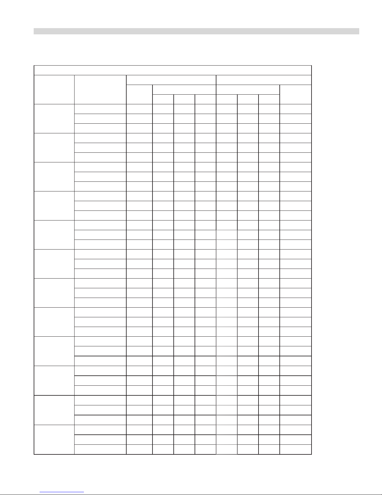
DIMENSIONS AND SPECIFICATIONS
OVERALL DIMENSIONS
MODEL
NUMBER
EDU-15HSE 15 381 24 610 11.25 286
EDU-18F 18 457 24 610 13 330
EDU-15SF 18 457 24 610 13 330
EDU-36FT 36 914 24 610 13 330
EDU-36SFT 30 914 24 610 13 330
EDU-15G 15 381 24 610 13.75 349
EDU-24G 24 620 24 610 13.75 349
EDU-36G 36 914 24 610 13.75 249
EDU-15B 15 381 24 610 13.75 349
EDU-30B 30 762 24 610 13,75 349
EDU-42B 42 1067 24 610 13.75 349
EDU-15W 15 381 24 610 11.50 292
Width Depth Height
In mm In mm In mm
MODEL PRODUCT DESCRIPTION
EDU-15HSE 15” (381mm) Wide Hot Plate With 8” (203mm) Solid Elements
EDU-18F 18” (457mm) Wide Fryer 5.3kw
EDU-18SF 18” (457mm) Wide Fryer 8.0 Kw
EDU-36FT 36” (914 Mm) Wide Twin Fryer 10.6 Kw
EDU-36SFT 36” (914 Mm) Wide Twin Fryer 16.0kw
EDU-15G 15” (381mm) Wide Griddle
EDU-24G 24” (610mm) Wide Griddle
EDU-36G 36” (914mm) Wide Griddle
EDU-15B 15” (381mm) Wide Broiler
EDU-30B 30” (762mm) Wide Broiler
EDU-42B 42” (1067mm) Wide Broiler
EDU-15W 15” (381mm) Wide Food Warmer
Part # 4521353 (06/17/09)Page 4
Page 5
DIMENSIONS AND SPECIFICATIONS continued
LOADING CHART
KW LOAD AMPS
MODEL VOLTAGE
220V/380V 2N~ 4.8 2.4 2.4 0.0 10.8 10.8 0.0 21.6
EDU-15HSU
EDU-18F
EDU-18SF
EDU-36FT
EDU-36SFT
EDU-15G
EDU-24G
EDU-36G
EDU-15B
EDU-30B
EDU-42B
EDU-15W
230V/400V 2N~ 5.2 2.6 2.6 0.0 11.3 11.3 0.0 22.6
240V/415V 2N~ 5.2 2.6 2.6 0.0 10.8 10.8 0.0 21.7
220V~ 5.93 5.93 0.0 0.0 27.0 0.0 0.0 27.0
230V~ 5.3 5.3 0.0 0.0 23.0 0.0 0.0 23.0
240V~ 5.3 5.3 0.0 0.0 22.1 0.0 0.0 22.1
220V/380V 3N~ 7.3 2.4 2.4 2.4 11.1 11.1 11.1 33.2
230V/400V 3N~ 8.0 2.7 2.7 2.7 11.6 11.6 11.6 34.7
240V/415V 3N~ 8.0 2.7 2.7 2.7 11.1 11.1 11.1 33.2
220V/380V 2N~ 11.86 5.93 5.93 0.0 27.0 27.0 0.0 53.9
230V/400V 2N~ 10.6 5.3 5.3 0.0 23.0 23.0 0.0 46.1
240V/415V 2N~ 10.6 5.3 5.3 0.0 22.1 22.1 0.0 44.2
220V/380V 3N~ 14.6 4.9 4.9 4.9 22.2 22.2 22.2 66.5
230V/400V 3N~ 16.0 5.3 5.3 5.3 23.2 23.2 23.2 69.5
240V/421V 3N~ 16.0 5.3 5.3 5.3 22.2 22.2 22.2 66.6
220V~ 2.8 2.8 0.0 0.0 12.8 0.0 0.0 12.8
230V~ 3.4 3.35 0.0 0.0 14.6 0.0 0.0 14.6
240V~ 3.4 3.35 0.0 0.0 14.0 0.0 0.0 14.0
220V/380V 2N~ 5.6 2.8 2.8 0.0 12.8 12.8 0.0 25.6
230V/400V 2N~ 6.7 3.35 3.35 0.0 14.6 14.6 0.0 29.1
240V/415V 2N~ 6.7 3.35 3.35 0.0 14.0 14.0 0.0 27.9
220V/380V 3N~ 8.4 2.8 2.8 2.8 12.8 12.8 12.8 38.4
230V/400V 3N~ 10.1 3.35 3.35 3.35 14.6 14.6 14.6 43.7
240V/415V 3N~ 10.1 3.35 3.35 3.35 14.0 14.0 14.0 41.9
220V ~ 2.3 2.3 0.0 0.0 10.3 0.0 0.0 10.3
230V ~ 2.7 2.7 0.0 0.0 11.7 0.0 0.0 11.7
240V ~ 2.7 2.7 0.0 0.0 11.3 0.0 0.0 11.3
220V/380V 2N~ 4.5 2.3 2.3 0.0 10.3 10.3 0.0 20.6
230V/400V 2N~ 5.4 2.7 2.7 0.0 11.7 11.7 0.0 23.5
240V/415V 2N~ 5.4 2.7 2.7 0.0 11.3 11.3 0.0 22.5
220V/380V 3N~ 6.8 2.3 2.3 2.3 10.3 10.3 10.3 30.9
230V/400V 3N~ 8.1 2.7 2.7 2.7 11.7 11.7 11.7 35.2
240V/415V 3N~ 8.1 2.7 2.7 2.7 11.3 11.3 11.3 33.8
220V~ 1.12 1.12 0.0 0.0 5.1 0.0 0.0 5.1
230V~ 1.1 1.1 0.0 0.0 4.8 0.0 0.0 4.8
240V ~ 1.0 1.0 0.0 0.0 4.2 0.0 0.0 4.2
TOTAL
PER PHASE PER PHASE
L1 L2 L3 L1 L2 L3
1 PHASE
Part # 4521353 (06/17/09) Page 5
Page 6

INTRODUCTION
IMPORTANT: The following instructions should be read
carefully as the manufacturer can not be held responsible for
any damage to property or persons as caused by incorrect
installation or operation of this equipment.
You have just purchased the nest commercial cooking
equipment available anywhere. Like any other ne,
precision built appliance, it should be given regular care
and maintenance. Periodic inspections by your dealer or a
qualied service agency are recommended.
Your new equipment must be installed and adjusted by a
competent person in accordance with the law. Failure to
install appliances correctly could lead to prosecution. It is
in your own interest and that safety to insure that the law is
compiled with.
Your Garland dealer or local authorized service agency is well
qualied to provide this service. Periodic inspections by your
dealer or a qualied service company are recommended
to check temperatures and to insure that moving parts
are operating. Whenever possible avoid overheating idle
equipment for this is the primary cause for increased service
cost.
Factory specied replacement parts must be used to
maintain listing. Use of “Generic” replacement parts may
create a hazard and will void the listing.
Unpacking
Product Application
Preparation of soups, stocks or sauces is done on a hot
plate where slow even cooking is desirable. Heating larger
quantities of food can be done more eciently than heating
small quantities. Pot and pans should be covered whenever
possible to reduce energy consumption.
High acid sauces, such as tomato should be cooked in
stainless steel vessels rather than aluminum since stainless
will not react chemically. Light colored sauces may be
discolored by the use of aluminum especially if stirred with
a metal spoon. Salty water may pit aluminum vessels if used
frequently.
NOTE: Many parts of the equipment are raw steel, i.e.,
griddle top, top grates, rings etc. and can react with moisture
forming rust. This is normal and not considered a defect.
Clean with stainless steel or ber pad. A light coating of salt
free oil may be applied to prevent further rusting.
Serial Plate
All electrical ratings are shown on the serial plate of each
unit and are readily visible by opening the enameled door
located below the control panel.
For proper operation, the information noted on the serial
plate of your new equipment must match your electrical
supply.
1 Check the crate/carton for possible damage sustained
during transit. Carefully remove the unit from the crate/
carton and again check for damage. Any damage must be
reported to the carrier immediately.
2. Any protective material covering stainless steel parts
must be removed.
3. The type of voltage supply that the equipment was
manufactured for at the factory is noted on the serial
plate and the packaging. This type of supply must be
used.
4. Do not remove permanently xed labels, warnings
or serial plates from the appliance, for this many void
approvals and create a safety hazard.
In the event you have any questions concerning the
installation, use, care or service of this or any other Garland
product, write or call our Product Service Department. When
corresponding with the factory or your local authorized
factory service center regarding service problems or
replacement parts, be sure to refer to the particular unit by
the correct model number (including the prex and sux
letters and numbers) and the warranty serial number. The
serial plate axed to the unit contains this information.
Part # 4521353 (06/17/09)Page 6
Page 7
GENERAL INSTALLATION
REAR VIEW
Introduction
The Garland EDU series 230V and 240V complies with
the essential requirement of the directives 73/23/EEC,
89/336EEC, 93/68/EEC and the standards; EN60335, IEC529,
EN5501, eN6100-4-A, ENV502404, EN61000-4-4, ENV50142,
IEC1000-4-11, ENV50141. Also complies with the latest
edition of NSF#4.
Safety
This manual pertains to the EDU series counter equipment.
The reader/operator must interpret its contents to applicable
needs. If there is any question of interpretation of any
literature, please contact your authorized service agency or
our customer service department at the phone number in
the information pamphlet.
A qualied person must make the installation of these
products in accordance with local codes.
Always follow these safety precautions when operating these
appliances.
These units must only be operated by qualied persons. DO
NOT operate with out reading this manual.
DO NOT operate the appliance unless all service and access
panels are in place and fastened properly.
Electrical Supply
Before attempting the electrical connection, the serial plate
should be checked to ensure that the equipment’s electrical
characteristics agree.
The supply terminal block is accessible from the font. The
electrical supply must be adequate for the voltage, phase
and current marked on the serial plate.
Note: a means of disconnection from the supply having
a contact separation of at least 3 mm (0.12”) must be
incorporated in the xed wiring.
This equipment is intended to be installed with xed
permanent wiring.
Warning: This appliance must be earthed.
Single and three-phase connection:
Unless otherwise noted, all appliances are shipped from
the factory for three phase connection. A wiring diagram is
attached to the rear each appliance. Visually check all the
electrical connections. The appliance is wired at the factory
as specied on the order. If it is necessary to change the
phasing, refer to the wiring diagram.
Installation Of Banking Plates
DO NOT attempt to repair or place any part of these
appliances unless all main power supplies have been
disconnected.
WARNING
To avoid personal injury; use extreme caution in setting up,
operating and cleaning these appliances to avoid coming
in contact with hot surfaces. Suitable protective clothing
should be worn or proper utensils used to prevent the risk of
burns.
Note all warning labels and marking on the appliance, which
call attention to further dangers and necessary precautions.
THESE APPLIANCES SHOULD NOT BE CLEANED WITH A
WATER JET.
Ventilation
The area in which the appliance is installed must be
adequately ventilated to provide air for removal of steam,
heat generated by the appliance etc. the use of mechanical
extract system should be considered and conform to local
codes.
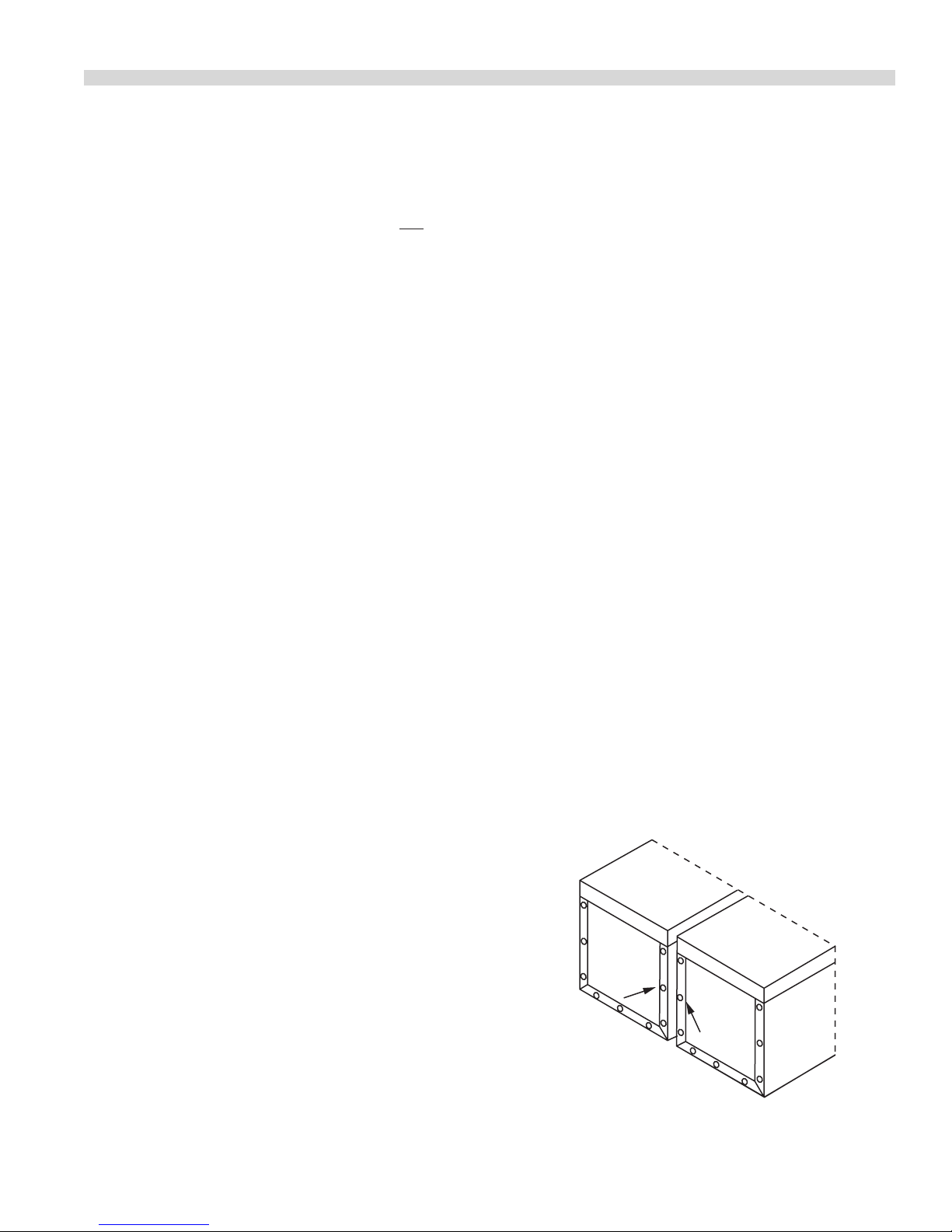
All units may be installed independently or banked with
other ED or GD series equipment. To ensure a matching
and permanent t between units, two banking plates are
available for each unit to be installed. One at the front and
one at the rear of each two units being banked together.
If optional 4” (102mm) legs are supplied with unit, discard
leveling bolts and replace with legs.
Part # 4521353 (06/17/09) Page 7
Page 8
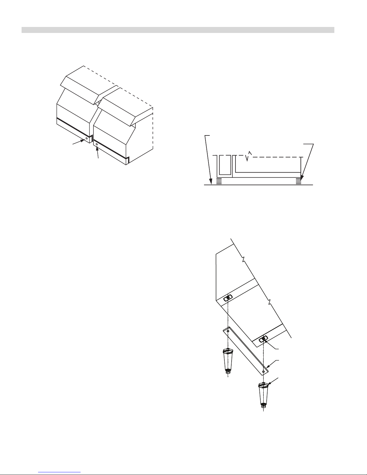
FRONT VIEW
GENERAL INSTALLATION continued
COUNTER TOP
SILICONE SEALANT
BOTTOM OF UNIT
LEG CHANNEL
(QTY 2)
4" [102mm]
ADJUSTABLE LEG
(QTY 4)
LEG INSTALLATION
3. Lay a generous bead of silicone under the entire
4. Secure unit to counter top through the holes located on
5. Smooth the silicone seal into the crevice with nger or
1. Level each unit by adjustment of leveling bolts or legs.
Use a spirit level and level unit four ways; across front and
back and down left and right edges. Level all other units
to the rst unit.
NOTE: Griddles may not rest evenly on the unit body if units
are not leveled.
2. Remove acorn nuts at rear of unit.
Leg Installation
The leg channel is located onthe package base. This channel
must be installed when using the legs.
perimeter of appliance bottom.
the underside of the appliance using 10A sheet metal
screws.
tool to provide a cove seal.
3. Attach one banking plate in position at rear by placing
1/4” (6.4 mm) diameter holes in the banking plate over the
screw holes in the rear of units and fasten by replacing the
acorn nuts removed in step 2.
4. Push units into position on counter top or back bar.
5. To secure the front, open the lower front panel, place
banking plate over the two holes (one on each unit) and
secure banking plate using sheet metal screws supplied.
Sanitary Counter Top Seal
When appliance is installed without legs on a counter top, it
must be sealed in accordance with N.S.F. standards as per the
following instructions:
1. Appliance should be located on a level counter top
surface. Complete the electrical connection.
2. Thoroughly clean the appliance bottom perimeter and
the counter top area around the appliance perimeter.
Part # 4521353 (06/17/09)Page 8
Page 9

GENERAL INSTALLATION continued
Installation Of Counter Stands (Optional)
1. Assemble and level counter stand as illustrated in the
instructions found in the counter stand carton.
2. Remove and discard leveling bolts on unit to be installed
on counter stand.
3. Place units in desired position on counter stand, securing
the rst unit with 8-32 machine screws and at washers.
Insert 8-32 machine screws through the 7/32” (5mm)
diameter holes in stand into the nutserts in the bottom of
EDU Series unit.
4. Connect banking plates as described in section titled,
5. Secure last unit to counter stand with 8-32 machine screws
INDIVIDUAL MODEL INSTALLATIONS
Solid Element Hot Plate;
Model EDU-15HSE
Wall Clearances
Do not install the appliance closer to a wall of combustible
material than :
Back: 1-1/2” (38mm)
Sides 1-1/2” (38mm)
Electrical Supply
Before attempting the electrical connection, the rating noted
on the serial plate should be checked, to ensure that the
appliance electrical characteristics and the supply electrical
characteristics agree. The electrical supply must be adequate
for the voltage, phase and current marked on the serial plate.
Use only wires suitable for 75°C (167°F).
Controls
Solid element hot plates are controlled by six heat switches.
There are three boiling and three simmering positions. Turn
the switch left or right from the o position to the desired
number, one being the lowest setting and six being the
highest.
Switch
Position
Installation of Banking Plates.
and at washers. Inserts 8-32 machine screws through
the 7/32” (5mm) diameter holes in stand into the nutserts
in the bottom of EDU series unit.
Wattage Heat
1 240
2 340
3 450 Medium
4 1300
6 2600
Low
(Simmer)
High (Boil)5 1750
The supply cable entrance is located on the right side, when
facing the rear of the unit. The cable is fed towards the front
through a wire way.
A knockout is provided near the front left side of the unit,
located behind the control panel. To access the knockout,
loosen the two acorn nuts and hinge the control panel
downwards. The terminal block is also located in this area.
Part # 4521353 (06/17/09) Page 9
This hot plate is protected against overheating when
running empty or when using poor quality cookware, by a
unique built-in bimetal protector switch. The protector cuts
down the power automatically under the above conditions
before overriding the regulator switch and returning itself to
normal, this is an important feature.
Page 10

INDIVIDUAL MODEL INSTALLATIONS continued
Before Operating the Hot Plate
The top working surface has a heat resistant coating. Before
using the sealed hot plates for the rst time, they should
be heated for a short period without a pan, to harden and
burn o the protective coating (3-5 minutes at the highest
setting).
Fryers: Models EDU-18F, EDU-18SF,
EDU-36FT And EDU-36SFT
Wall Clearances
Do not install appliance closer to a wall of combustible
material than:
Back: 0”
Sides: 0”
Electrical Supply
Before attempting the electrical connection, the rating
on the serial plate should be checked to ensure that the
appliance electrical characteristics and the supply electrical
characteristics agree. The electrical supply must be adequate
for the voltage, phase and current marked on the serial plate.
Use only wires suitable for 75° C (167°F).
A knockout is provided on the right side, when facing the
rear of the unit, for the supply cable entrance. Access to the
terminal block is gained by removing the fry tank assembly,
the rear shield and contactor box cover, all are located at the
rear of the fryer.
Controls
1. All EDU series fryers are equipped with a manually
re-settable high limit, located at the rear of the
element termination box. In the event that shortening
temperatures exceed normal limits, the high limits will
trip and can only be reset by pushing the red button
when the shortening has cooled.
2. All EDU series fryers are equipped with a precision
electronic thermostat, which has been factory calibrated
and is designed to hold that calibration. There should
never be the need to calibrate this thermostat in the eld.
Should there ever be an abnormal discrepancy in the set
point and actual temperatures, or repeated tripping of
the new high limit occurs, this fryer should be serviced by
an authorized Garland service agency.
Before Operating the Fryer
1. Before leaving the factory, the fryer was tested and the
thermostat calibrated with oil in the fry tank. Therefore it
is necessary to clean the fry tank and the elements before
lling with frying compound. Use detergent or other
cleaning agents, with hot water. Thoroughly rinse and dry
the fry tank.
2. To remove the fry tank, raise the element assembly by
means of the handle until the support engages, holding
the element assembly in the upright position. The
element assembly is lowered by moving the support/lock
stop to release the element assembly from the upright
position.
Griddles: Models
EDU-15G, EDU-24G, EDU-36G,
Grooved Griddles: Models
EDU-15G-U, EDU-24G-U, EDU-24G-U1, EDU36G-U, EDU-36GU1, EDU-36G-U2
Wall Clearances
Do not install appliance closer to a wall of combustible
material than:
Back: 1-1/2” (38mm)
Sides: 1” (25mm)
Electrical Supply
Before attempting the electrical connection, the rating
on the serial plate should be checked to ensure that the
appliance electrical characteristics and the supply electrical
characteristics agree. The electrical supply must be adequate
for the voltage, phase and current marked on the serial plate.
Use only wires suitable for 75° C (167°F).
The supply cable entrance is located on the right side, when
facing the rear of the unit. The cable is fed toward the front
through a wire way.
A knockout is provided near the front side of the unit, located
behind the control panel. To access the knockout, loosen the
two acorn nuts and hinge the control panel downwards, the
terminal block is located in this area.
Part # 4521353 (06/17/09)Page 10
Page 11

INDIVIDUAL MODEL INSTALLATIONS continued
Controls
All EDU griddles are equipped with snap action thermostats.
Before Operating the Griddle
1. Remove the protective coating on the griddle
surface and side splashers using a mild
detergent.
2. Thoroughly rinse the griddle with a vinegar water
solution (3/4 cup vinegar per quart of water) and dry
thoroughly with a clean cloth.
3. The Griddle must be seasoned before operation, see the
general maintenance and cleaning section for seasoning
instructions.
Calibration Instructions
1. Field calibration is seldom necessary and should not
be attempted unless experience with cooking results
denitely proves that the control is not maintaining the
temperature to which the dial is set.
2. Should calibration be required, use a test instrument
(pyrometer) with a special disc type thermocouple or
reliable “surface” type thermometer. Note: A drop of oil on
the face of the disc will provide a better contact.
3. Turn the griddle temperature dials to 350°F (177°C). In
order to allow the griddle temperatures to stabilize, the
controls must be allowed to cycle twice before taking a
test reading.
4. Check the temperature reading when the control has just
cycled “OFF” (as indicated by the cycling amber pilot), by
placing the sensor rmly on the griddle surface, directly
above the sensing bulb of the control. If the temperature
does not read with in 8° C (15°F) of the dial setting,
recalibrate as follows:
5. Carefully remove the thermostat dial making sure that
the setting is not disturbed.
6. Hold the dial shaft steady and with a slim screwdriver,
turn the calibration screw, located in the dial shaft,
clockwise to decrease and counter clockwise to increase
the temperature. Example: 1/4 Turn = 18° C (35°F).
7. Replace the thermostat dial and repeat steps 2 though 4
to verify that the correct adjustment has been made.
Broilers: Models
EDU-15B, EDU-30B And EDU-42B
Wall Clearances
Do not install closer to a wall of combustible material than:
Back: 9” (229mm)
Side: 9” (229mm)
Electrical Supply
Before attempting the electrical connection, the rating
on the serial plate should be checked to ensure that the
appliance electrical characteristics and the supply electrical
characteristics agree. The electrical supply must be adequate
for the voltage, phase and current marked on the serial plate.
Use only wires suitable for 90° C (194°F).
The supply cable entrance is located on the front side, when
facing the rear of the unit. The cable is fed toward the front
through a wire way.
A knock out is provided near the front left side of the unit,
located behind the control panel. To access the knockout,
loosen the two acorn nuts and hinge the control panel
downwards, the terminal block is located in this area.
Controls
Innite switches (energy regulators) are used to control the
elements.
High to 5 High heat
5 to 3 Medium heat
3 to Lo Low heat
Setting the switched between these numbers will give
intermediate heat. Switches are reversible and may be
turned left or right.
Before Operating the Broiler
1. Before leaving the factory, the castings were coated with
oil to prevent corrosion. Therefore, it is necessary to clean
the castings before seasoning and cooking.
2. Turn the broiler control dial/s to “HI” and allow to run
empty for 15 minutes. Turn the dial/s to “OFF” and allow
castings to cool. Clean o any residue with a detergent
soaked cloth.
Part # 4521353 (06/17/09) Page 11
Page 12

INDIVIDUAL MODEL INSTALLATIONS continued
3. Using a dry cloth, rub a thin layer of cooking oil into the
casting surface. Oil should be an unsalted shorting or
high temperature cooking oil. Turn the control dial/s to
#4 and allow to run empty for 15 to 30 minutes. This will
season the cooking surface and prevent product from
sticking.
Food Warmer: Model EDU-15W
Wall Clearances
Do not install closer to a wall of combustible material than:
Back: 1” (25mm)
Sides: 1” (25mm)
Electrical Supply
Before attempting the electrical connection, the rating
on the serial plate should be checked to ensure that the
appliance electrical characteristics and the supply electrical
characteristics agree. The electrical supply must be adequate
for the voltage, phase and current marked on the serial plate.
Use only wires suitable for 90° C (194°F).
The supply cable entrance is located on the right side, when
facing the rear of the unit. The cable is fed toward the front
through a wire way.
A knockout is provided near the front left side of the unit,
located behind the control panel. The access the knockout,
loosen the two acorn nuts and hinge the control panel
downward, the thermal block is located on this area.
Controls
Innite switches (energy regulators) are used to control the
elements.
High to 5 High heat
5 to 3 Medium heat
3 to Lo Low heat
Setting the switched between these numbers will give
intermediate heat. Switches are reversible and may be
turned left or right.
Before Operating the Warmer
Before use, it is recommended that the inside of the tank be
cleaned with a detergent soaked cloth, to remove fabricating
and protective oils. Rinse with clean water and dry with a
clean cloth.
COMMISSIONING
1. Ensure that all controls are in the o position and turn on
the main electrical supply.
2. Operate each section of (each) appliance in accordance
with the instructions given in the Operating section.
3. Check that the/each appliance functions correctly and
that the voltage supply to the/each appliance does
not drop more that 5% when all sections are operated
simultaneously.
4. When the operation has been checked, turn all controls
to the o position. Hand this manual to the purchaser
for retention and instruct them in ecient and safe
operation of the appliance/s. This manual should be
retained for future reference.
Part # 4521353 (06/17/09)Page 12
Page 13

OPERATING INSTRUCTIONS
Safety Concerns
It is the responsibility of the supervisor or equivalent person
to ensure that the users of this equipment wear suitable
protective clothing and draw attention to the fact that some
parts will, by necessity, become very hot and will cause burns
if touched accidentally.
Sealed Hot Plates
All purpose sealed top elements provide an easy-clean top.
They are intended for boiling, simmering, satué and other
top cooling.
Operating practices are very important for the ecient use of
these elements:
1. Pot bottoms must be at. This increased the heat transfer
to the pot. Do not use either convex or concave in excess
of 1 mm (1/32”).
2. Use pots with the same diameter as the element when
possible. This will reduce the heat up time.
3. Do not preheat the element. Elements are protected with
a high limit, which automatically reduces the element to
a lower power. It will increase the heat up if this occurs.
4. Use a lid to cover the posts when boiling water.
Operating The Sealed Hot Plate
1. Before using the sealed hot plates for the rst time, they
should be heated at a setting #3 for 5 minutes, then
turned o and allowed to cool. This will harden and burn
o the protective coating.
2. Set the six heat switch dial to the desired position for 1 to 6.
Sealed Hot Plate Application Guide:
Application Dial Setting Wattage
Boiling,
Frying,
Braising
Simmering
Warming 1 240
Shutting Down The Sealed Hot Plate:
6 2600
5 1750
4 1300
3 450
2 340
Fryers
Operating The Fryer:
1. For liquid frying compound, ll the fry tank to bottom oil
line stamped at the rear of the tank (9 liters, 8 quarts). This
allows for oil expansion as heat is applied. Do not ll with
cold oil any higher than the bottom line; overow may
occur as heat expands the oil. Set the power switch to
the “ON” position and turn the thermostat to the desired
frying position.
2. If a hydrogenated (solid) frying compound is used,
measure 17 pounds (7.7 Kg) into the dry tank. Note: pack
the compound, to ensure that the element assembly is
completely covered with the compound.
CAUTION: Never set a complete block of solid shortening on
top of heating elements.
3. Set the power switch to the “ON” position and turn
the thermostat dial to 121°C (250°F) until enough
of the compound has melted to cover the element
assembly. Then turn the thermostat to the desired frying
temperature.
4. Ensure that the oil level is at the top OIL LEVEL line when
the oil is at its cooking temperature. It may be necessary
to add oil or shortening to bring the levels up to the
proper mark, after reaching cooking temperature.
5. Never place more product in the basket than half full.
Griddles
Griddle tops are designed to have food cooked directly on
the surface. Do not put pots or pans on the griddle surface,
since this will scratch or nick the surface and result in
improper cooking or sticking of product. Never salt food over
a griddle since this will built up a gummy residue making it
dicult to clean.
Avoid hitting the surface of the griddle with the edge a
spatula since it will cause nicks. The most frequently used
temperatures are 149° C to 177°C (300° F to 500° F). After one
ring, the griddle plate will discolor, this is normal and will not
aect cooking performance.
Note: The griddle must be seasoned before initial use, see
griddle seasoning in General Maintenance and Cleaning
section.
1. Turn the six heat switch to the “OFF” position.
Part # 4521353 (06/17/09) Page 13
Page 14

OPERATING INSTRUCTIONS continued
Operating the Griddle:
Note: Ensure that the electrical supply to the appliance is
turned “ON”.
1. Set the thermostat/s to the desired temperatures.
2. The griddle is ready for use when the amber indicator
light cycles o.
Shutting Down The Griddle:
1. Turn the thermostat/s to the “OFF” position.
Broilers
Operating The Broiler:
Innite switches are used to control broiler casting
temperatures.
“Hi” to 5 for high heat (Hi being the maximum).
5 to 3 for medium heat.
3 to ‘’Lo” for low heat.
Setting the switches between any of the above numbers will
give intermediate heat. Switches are reversible and may be
turned right or left.
Food Warmers
CAUTION: DO NOT OPERATE THE WARMER DRY! THE WARMER
MUST BE OPERATED WITH WATER IN THE TANK.
The food warmer has been designed to have water in the tank
for even heating. The end walls of the tank have embossed
lines. The higher line is for “max”, the lower for “min”. The tank
should be lled with clean water to a point between the two
lines. Do not ll about the top line, nor below the bottom line.
Water will evaporate during use, do not allow water to fall
below the bottom line.
Operating The Food Warmer
A innite switch is used to control the temperature in the
tank.
“Hi” to 5 for high heat (Hi being the maximum).
5 to 3 for medium heat.
3 to ‘’Lo” for low heat.
Setting the switches between any of the above numbers will
give intermediate heat. Switches are reversible and may be
turned right or left.
Note: Periodic checks should be made during operation to
ensure that the water level does not go below the lower
embossed line. Should it do so, top o with fresh water.
GENERAL MAINTENANCE AND CLEANING
WARNING: THESE APPLIANCES SHOULD NOT BE CLEANED
WITH A WATER JET.
General Cleaning
Stainless steel should be cleaned using a mild detergent,
a soft cloth and hot water. If it is necessary to use a nonmetallic scouring pad, always rub in the direction of the grain
in the metal to prevent scratching. Wash a small area at a
time and rinse the washed area with a clean sponge dipped
into a disinfectant and wipe dry with a soft clean cloth before
it can dry.
Use only stainless steel, wood or plastic tools to scrape
o heavy deposits of grease or oil. Do not use ordinary
steel scrapers or knives, as particles of iron may become
embedded and rust.
NEVER USE STEEL WOOL.
Enameled surfaces should be allowed to cool down before
cleaning. Wipe exposed cleaning, when cool, with a mild
detergent and hot water. Stubborn reside spots may be
removed with a scouring pad. Dry thoroughly with a clean
cloth.
Painted surfaces should only be cleaned with a mild
detergent. Rinse with a clean sponge and hot water. Dry
thoroughly with a clean cloth. NOTE: Use of a scouring pad or
powdered cleanser on painted surfaces will wear away paint
surfaces and must be discouraged.
Part # 4521353 (06/17/09)Page 14
Page 15

GENERAL MAINTENANCE AND CLEANING continued
Hot Plates
The design of the sealed hot plates provides an easy clean
top surface. Clean any spills with a cloth soaked in a mild
detergent and hot water. For any build up of burned on
grease or food spills, use only a non metallic scouring pad,
always rub in the direction of the grain of the metal to
prevent scratching. Rinse with a sponge dipped in clean hot
water and dry thoroughly with a clean cloth.
Fryers
Cleaning The Fry Tank
1. If a liquid frying compound is used, allow the compound
to cool, then raise the element assembly by means of the
handle until the support engages and let the oil run o
the elements into the fry tank. Wipe the surface oil o the
elements to prevent dripping into the unit bottom when
the tank is removed. Lift out the fry tank and empty the
oil into a lter, after ltering it is then ready for re-use.
Clean the tank in the pot wash area with a mild detergent
and hot water. Rinse with a sponge dipped in a vinegar
and water solution. (3/4 cup of vinegar to 1 quart of
water) and dry thoroughly with a clean cloth.
2. If hydrogenated (solid) frying compound is used that has
been allowed to cool and become solidied, rst turn the
thermostat dial to 121°C (250°F) until the compound is
in a liquid state. Turn the thermostat dial/s to o “O”. Lift
the element assembly by means of the handle until the
support engages and let the oil run o the elements into
the fry tank. Then proceed as described in step 1 to lter
the compound and clean the fry tank.
3. Clean the top of the unit with a cloth soaked in a mild
detergent and hot water, including the front of the
element assembly housing. Rinse with a clean cloth
dipped in clean hot water, Dry thoroughly with a clean
cloth.
4. Repeat step 1 and set the thermostat dial/s to 135°C
(275°F).
5. Repeat steps 2&3. The griddle is now ready for use.
Cleaning The Griddle
1. Use a standard 64-76mm (2-1/2 to 3”) scraper or spatula,
scrape the griddle surface (to remove food particles or oil
residue) towards the grease trough using even back to
front strokes. Deposit debris into the chute.
2. Pour shortening or oil onto the griddle surface, using a
front to back motion. Clean the griddle using a griddle
stone or grill screen. Always with the grain of the steel,
never sideways.
3. Using a clean cloth, rub a thin layer of cooking oil onto
the griddle surface.
4. Remove the grease drawer, empty and wash thoroughly
with a mild detergent and water. Repeat.
5. Re-season the griddle as detailed above. The griddle is
now ready for use.
Griddles Do’s and Don’t’s
D o’s
1. Season the griddle. This will prevent foods from sticking
and make it easier to keep the surface clean.
2. Keep the surface clean. Scraping the surface throughout
production to clear food and oil prevents build up
and will conserve energy and prevent the plate from
overheating.
3. Turn the temperature down during slow periods.
Reducing the temperature or turning sections o during
slow periods will conserve energy and prevent the plate
from overheating.
Griddles
Seasoning The Griddle
1. Using a clean cloth rub a thin layer of cooking oil onto
the griddle surface. Oil should be an unsalted shorting or
high temperature cooking oil.
2. Set the griddle thermostat dial/s to 55°C (130°F) and
heat the griddle surface until the oil begins to caramelize
(turning a golden brown). Once this occurs, turn the
thermostat dial/s to “OFF”.
3. Scrape o the caramelized oil with a standard spatula.
Part # 4521353 (06/17/09) Page 15
Don’t’s
1. Do not use salt to clean the griddle surface. Salt is
corrosive and can cause pitting on the griddle.
2. Do not allow metal utensils (spatula, scraper, etc.) to
nick and/or dent the surface of the griddle. The edges of
these utensils are sharp and will create divots were oil can
collect in and caramelize which causes sticking.
3. Do not use the griddle as a hot top. A large pan or pot will
trap the heat and cause the griddle plates to warp.
Page 16

GENERAL MAINTENANCE AND CLEANING continued
4. Do not set the thermostat dials to high stop to preheat
faster. Preheating at the desired temperature takes 15-20
minutes. High stop does not heat faster and only serves
to overheat the griddle.
Broiler
Cleaning (After Each Use)
To clean the broiler castings after a period of heavy use, turn
the control switch dial/s to “HI”. This will creates a “self-clean”
burn o of product residue oil, continue until incinerating
smoke reduces. Turn the switch dials to o (“O”) and allow to
cool. With a sti brush, clean the castings from front to back.
Complete the casting cleaning process with a cloth soaked in
a mild detergent and hot water solution. (3/4 cup of vinegar
per quart of water) and dry thoroughly with a clean cloth.
Tilt the castings up and clean the grease collector under the
castings, pushing any food residue through the opening into
the grease tray.
Remove the grease tray, drain and thoroughly clean with a
mild detergent and hot water. Rinse and dry thoroughly.
After cleaning the castings, rub a thin layer of oil onto the
casting surface with a clean cloth. The broiler is now ready for
use.
Food Warmers
Empty the water from the tank and clean any lime deposit
with a non-metallic scouring pad. Clean with a cloth soaked
in a mild detergent and hot water. Rinse with a sponge
dipped in clean hot water and dry with a clean cloth.
The top of the unit can be cleaned with a cloth soaked in
a mild detergent and hot water. For food spill build up, a
non-metallic scouring pad can be used, always rub in the
direction of the grain of the metal to prevent scratching.
Rinse with a sponge dipped in clean hot water and dry
thoroughly.
Regular Maintenance And Service
To ensure long life, ecient and safe operation of you
equipment, it is recommended that a maintenance and
servicing program be carried out at regular intervals, the
frequency of which will vary, depending on the installation
conditions and amount of usage. Usually once per year is
adequate.
Servicing must be carried out by competent persons in
accordance with the law.
It is essential that the instructions in this manual are strictly
followed for the safe and economical operation of the
equipment. If it is known or suspected that a fault exists on
an appliance, that appliance must not be used until the fault
has been rectied by a competent person.
SERVICING
Regular servicing by a competent person according to the
law is recommended to ensure the continued safe and
ecient performance of the appliance/s.
Factory specied replacement parts must be used to
maintain listing. Use of “Generic” replacement parts may
create a hazard and will void the listing.
We suggest that servicing be performed by your local
authorized service agency or other competent persons,
according to the law.
Warning: Turn o the electrical mains before commenting
any service work.
Hot Plates
Elements:
If it is necessary to replace a faulty solid element, rst turn o
all electrical mains.
1. Loosen the two acorn nuts that secure the control panel
and hinge the panel downwards.
2. Remove the two screws that secure the element access
plate in the switch guard. Remove the access plate.
Part # 4521353 (06/17/09)Page 16
Page 17

SERVICING continued
3. Reach in though the access opening with a 10mm
wrench and remove the nuts that secure the wire-way,
at the center of each element and drop the wire-way.
Remove the second nut that at the center of the element,
remove the ground wires and drop the second screening
sheet. Lift out the faulty element.
4. Remove one wire at a time for the faulty element and
immediately connect it to the same terminal on the
replacement element. Discard faulty element.
5. Install the replacement element in the hot plate top with
the element terminations in the original position. Secure
with the screening sheet, ground wire and nut.
6. Reassemble in the reverse order.
Six Heat Switch
If it is necessary to change faulty switch, rst turn o
electrical mains.
1. Loosen the two acorn nuts securing the control panel
and hinge the control panel downwards.
2. Remove the dial from the faulty switch and remove the
two screws that secure the switch to the control panel.
Leave the wires attached to the faulty switch, until the
replacement switch has been mounted on the control
panel.
3. Remove one wire at a time from the faulty switch and
immediately connect it to the same terminal on the new
switch.
4. Reassemble in the reverse order.
Indicator Lamp:
If it is necessary to change the indicator lamp, rst turn o
the electrical mains.
Thermostat:
If it is necessary to replace a thermostat, rst turn o the
electrical main.
1. Loosen the two acorn nuts securing the control panel
and hinge the control panel downward.
2. Remove the clip/s that secures the griddle to the body, at
the front.
3. Raise the griddle and engage the support prop in the
hole in the switch guard.
4. Loosen the two nuts that secure the clamp over the
sensing bulb and withdraw this bulb.
5. Remove the two screws that secure the thermostat to the
control panel, after rst removing the control dial.
6. Disconnect the wires from the taps on the thermostat. Be
sure to note which terminal on the thermostat.
7. Remove the faulty thermostat and re-assemble the
replacement thermostat in the reverse order.
Indicator Lamp:
If it is necessary to replace an indicator lamp, rst turn o the
electrical mains.
1. Loosen the two acorn nuts securing the control panel
and hinge the panel downward.
2. Disconnect the supply wires to the lamp body and
remove the faulty lamp.
3. Install the replacement lamp in the control panel.
4. Reassemble in the reverse order.
Element:
1. Loosen the two acorn nuts securing the control panel
and hinge the panel downwards.
2. Disconnect the supply wires to the lamp body and
remove the faulty lamp.
3. Install the replacement lamp in the control panel.
4. Reassemble in reverse order.
Griddles
Follow the instructions in Griddle installation, calibration to
check thermostat calibration.
Part # 4521353 (06/17/09) Page 17
If it is necessary to replace a griddle element, rst turn o all
the electrical mains.
1. Loosen the two acorn nuts securing the control panel
and hinge the control panel downward.
2. Remove the clip/s that secure the griddle to the body, at
the front.
3. Raise the griddle and engage the support prop in the
hole in the switch guard.
4. Disconnect the wires from the element terminal.
Page 18

SERVICING continued
5. Remove the wire grounding the element clamp to the
body and remove the nuts that secure the element
clamp/bae to the bottom of the griddle plate. Lower
the clamp/bae and remove the faulty element.
6. Reassemble the replacement element, secure properly
with the clamp/bae.
7. Reassemble in reverse order.
Broilers
Elements:
To replace a faulty element, rst turn o all electrical mains.
1. Raise the relevant casting sucient to remove the tilting
stop rod toward the rear.
2. Lift out the casting and element assembly. Remove the
clamps that secure the faulty element to the casting,
remove the four screws that secure the element to the
termination box and remove the faulty element.
3. Install the replacement element,
4. Reassemble in the reverse order.
Innite Switch (Energy Regulator):
To replace a faulty innite switch, rst turn o the electrical
mains.
1. Loosen the two acorn nuts that secure the control panel
and hinge the control panel downward.
2. Remove the dial of the faulty switch and remove the
two screws that secure the switch to the control panel.
Leave the wires attached to the faulty switch, until the
replacement switch has been mounted on the control
panel.
3. Remove one wire at a time from the faulty switch and
immediately connect it to the same terminal on the new
switch.
4. Reassemble in the reverse order.
2. Disconnect the supply wires to the lamp body and
remove the faulty lamp.
3. Install the replacement lamp in the control panel.
4. Reassemble in the reverse order.
Food Warmers
Elements:
If it is necessary to replace a faulty element, rst turn o the
electrical mains.
1. Lift out the tank. Remove the screws (4) that secure
the bae above the element and lift up the element.
Disconnect the wires from the element terminals and
take out the faulty element.
2. Reconnect the wires to the terminals of the replacement
element.
3. Reassemble in the reverse order.
Innite Switch:
If it is necessary to replace a faulty switch, rst turn o all
electrical mains.
1. Loosen the two acorn nuts securing the control panel
and hinge the panel downward.
2. Remove the dial from the faulty switch and remove the
two screws that secure the switch to the control panel.
Leave the wires attached to the faulty switch until the
replacement has been mounted on the control panel.
3. Remove one wire at a time from the faulty switch and
immediately connect it to the same terminal on the new
switch.
4. Reassemble in the reverse order.
Indicator Lamp:
If it is necessary to change the indicator lamp, rst turn o
the electrical mains.
Indicator Lamp:
If it is necessary to change the indicator lamp, rst turn o
the electrical mains.
1. Loosen the two acorn nuts securing the control panel
and hinge the panel downwards.
1. Loosen the two acorn nuts securing the control panel
and hinge the panel downwards.
2. Disconnect the supply wires to the lamp body and
remove the faulty lamp.
3. Install the replacement lamp in the control panel.
4. Reassemble in the reverse order.
Part # 4521353 (06/17/09)Page 18
Page 19

FAULT FINDING
If servicing is required, we suggest that servicing be performed by your local authorized service agency or other competent
persons, according to the law.
Sealed Hotplates Diagnostics
PROBLEM POSSIBLE CAUSE SOLUTION
Water in pot does not boil
or water takes too long
to boil; with switch set to
position “6”.
Tubular Hotplates Diagnostics
PROBLEM POSSIBLE CAUSE SOLUTION
Hotplate too hot or cold. Defective innite switch. Replace indenite switch.
Hotplate not heating at all Defective heating element. Replace element.
Pot has irregular bottom. Use a at bottom pot.
Pot too large for element size. Use a smaller diameter pot
Pot too small for element size. Use a larger diameter pot.
Element was preheated before pot was
placed on elements.
One element circuit may be defective. Replace heating element.
Six heat switch my be defective. Replace six heat switch.
Defective innite switch. Replace indenite switch.
Allow element to cool protector. Protector
will reset.
Fryer Diagnostics
PROBLEM POSSIBLE CAUSE SOLUTION
Power indicator is on.
Heating indicator comes
on. Fryer is not recovering
or heating evenly.
Red indicator light is on.
Fryer is not heating.
Power indicator is on.
Heating indicator is o.
Fryer is not heating. Red
indicator is o.
One or more elements are defective. Replace element.
Sensor is defective. Replace sensor.
Thermostat is defective. Replace thermostat.
A contactor is defective. Replace contactor.
High temperature limit has been tripped. Lift the elements and reset the limit red
button, the lower elements into fry tank.
Thermostat may be defective. Replace thermostat.
Contactor my be defective. Replace contactor.
HI Limit may be defective. Replace hi limit.
Sensor circuit open. Check sensor connection/replace sensor.
Thermostat may be defective. Replace thermostat.
Sensor my be defective. Replace sensor.
Short circuit in sensor connection. Check sensor connection/replace sensor.
Part # 4521353 (06/17/09) Page 19
Page 20

FAULT FINDING continued
Griddle Diagnostics
PROBLEM POSSIBLE CAUSE SOLUTION
Griddle too hot or
not hot enough.
Griddle heating unevenly. Adjacent section is operating at a dierent
Thermostat out of calibration. Recalibrate thermostat.
temperature.
A defective thermostat. Replace thermostat.
A defective element. Replace element.
Check adjacent section heating.
Griddle was not thoroughly heated
before use.
Allow more time for griddle to saturate;
increase warm up time.
Broiler Diagnostics
PROBLEM POSSIBLE CAUSE SOLUTION
Casting too hot or not hot
enough.
Casting heating unevenly
or not heating at all.
Defective innite switch. Replace innite switch.
Defective innite switch. Replace innite switch.
Defective element Replace element.
Food Warmer Diagnostics
PROBLEM POSSIBLE CAUSE SOLUTION
Food Warmer tank not hot
enough or too hot.
Defective innite switch. Replace innite switch.
Defective element Replace element.
Tank bottom is warped (possibly run dry) Replace tank.
Part # 4521353 (06/17/09)Page 20
Page 21

Part # 4521353 (06/17/09) Page 21
Page 22

Part # 4521353 (06/17/09)Page 22
Page 23

Part # 4521353 (06/17/09) Page 23
Page 24

 Loading...