

Page 1
INSTALLATION AND
AIR
PAC
OPERATION MANUAL
MODELS AP1, APA & AP4
ELECTRIC DECK OVEN OVENS
FOR YOUR SAFETY:
DO NOT STORE OR USE GASOLINE
OR OTHER FLAMMABLE VAPORS OR
LIQUIDS IN THE VICINITY OF
THIS OR ANY OTHER
APPLIANCE
Includes counter top and four compartment ovens
PLEASE READ ALL SECTIONS OF THIS MANUAL
AND RETAIN FOR FUTURE REFERENCE.
THIS PRODUCT HAS BEEN CERTIFIED AS
COMMERCIAL COOKING EQUIPMENT AND
MUST BE INSTALLED BY PROFESSIONAL
PERSONNEL AS SPECIFIED.
WARNING:
IMPROPER INSTALLATION, ADJUSTMENT,
ALTERATION, SERVICE OR MAINTENANCE
CAN CAUSE PROPERTY DAMAGE, INJURY,
OR DEATH. READ THE INSTALLATION,
OPERATING AND MAINTENANCE
INSTRUCTIONS THOROUGHLY
BEFORE INSTALLING OR
SERVICING THIS EQUIPMENT
INSTALLATION AND ELECTRICAL CONNECTION
MUST COMPLY WITH CURRENT CODES:
IN CANADA - THE CANADIAN ELECTRICAL
CODE PART 1 AND / OR LOCAL CODES.
IN USA – THE NATIONAL ELECTRICAL CODE
ANSI / NFPA – CURRENT EDITION.
ENSURE ELECTRICAL SUPPLY CONFORMS WITH
ELECTRICAL CHARACTERISTICS SHOWN ON
THE RATING PLATE.
Users are cautioned that maintenance and repairs must be performed by a Garland authorized service agent
using genuine Garland replacement parts. Garland will have no obligation with respect to any product that has been
improperly installed, adjusted, operated or not maintained in accordance with national and local codes or installation
instructions provided with the product, or any product that has its serial number defaced, obliterated or removed,
or which has been modified or repaired using unauthorized parts or by unauthorized service agents.
For a list of authorized service agents, please refer to the Garland web site at http://www.garland-group.com.
The information contained herein, (including design and parts specifications), may be superseded and is subject
to change without notice.
GARLAND COMMERCIAL INDUSTRIES
185 East South Street
Freeland, Pennsylvania 18224
Phone: (570) 636-1000
Fax: (570) 636-3903
GARLAND COMMERCIAL RANGES, LTD.
1177 Kamato Road, Mississauga, Ontario L4W 1X4
CANADA
Phone: 905-624-0260
Fax: 905-624-5669
Enodis UK LTD.
Swallow eld Way, Hayes, Middlesex UB3 1DQ ENGLAND
Telephone: 081-561-0433
Fax: 081-848-0041
Part # 1382636 Rev 05 (01/25/08) © 2004 Garland Commercial Industries, Inc.
Part # 1382636 Rev 5 (01/25/08) Page 1
Page 2

IMPORTANT INFORMATION
WARNING:
This product contains chemicals known to the state of california to cause cancer and/or birth defects
or other reproductive harm. Installation and servicing of this product could expose you to airborne
particles of glass wool/ceramic fibers. Inhalation of airborne particles of glass wool/ceramic fibers
is known to the state of California to cause cancer.
Part # 1382636 Rev 5 (01/25/08)Page 2
Page 3

TABLE OF CONTENTS
IMPORTANT INFORMATION. . . . . . . . . . . . . . . . . . . . . . . . . . . . . . . . . . . . . . . . . . 2
DIMENSIONS AND SPECIFICATIONS, MODELS AP1 & AP-A . . . . . . . . . . . . . 4
DIMENSIONS AND SPECIFICATIONS, MODEL AP4. . . . . . . . . . . . . . . . . . . . . . 5
INTRODUCTION. . . . . . . . . . . . . . . . . . . . . . . . . . . . . . . . . . . . . . . . . . . . . . . . . . . . . 6
Rating Plate . . . . . . . . . . . . . . . . . . . . . . . . . . . . . . . . . . . . . . . . . . . . . . . . . . . . . . . . . . . . . . . . . . . . . .6
INSTALLATION . . . . . . . . . . . . . . . . . . . . . . . . . . . . . . . . . . . . . . . . . . . . . . . . . . . . . . 6
Clearances . . . . . . . . . . . . . . . . . . . . . . . . . . . . . . . . . . . . . . . . . . . . . . . . . . . . . . . . . . . . . . . . . . . . . . .6
Location . . . . . . . . . . . . . . . . . . . . . . . . . . . . . . . . . . . . . . . . . . . . . . . . . . . . . . . . . . . . . . . . . . . . . . . . .6
Installation for Ovens Equipped with Legs . . . . . . . . . . . . . . . . . . . . . . . . . . . . . . . . . . . . . . . .6
Installation for Ovens Equipped with Casters . . . . . . . . . . . . . . . . . . . . . . . . . . . . . . . . . . . . . .6
Stacking Instructions . . . . . . . . . . . . . . . . . . . . . . . . . . . . . . . . . . . . . . . . . . . . . . . . . . . . . . . . . . . . . 6
Ventilation . . . . . . . . . . . . . . . . . . . . . . . . . . . . . . . . . . . . . . . . . . . . . . . . . . . . . . . . . . . . . . . . . . . . . . .7
Electrical Connections . . . . . . . . . . . . . . . . . . . . . . . . . . . . . . . . . . . . . . . . . . . . . . . . . . . . . . . . . . .7
OPERATION. . . . . . . . . . . . . . . . . . . . . . . . . . . . . . . . . . . . . . . . . . . . . . . . . . . . . . . . . 8
Break-In Period . . . . . . . . . . . . . . . . . . . . . . . . . . . . . . . . . . . . . . . . . . . . . . . . . . . . . . . . . . . . . . . . . .8
Start Up Procedure . . . . . . . . . . . . . . . . . . . . . . . . . . . . . . . . . . . . . . . . . . . . . . . . . . . . . . . . . . . . . . .8
CONCEPT OF AIR IMPINGEMENT COOKING . . . . . . . . . . . . . . . . . . . . . . . . . . . 9
COOKING CHART . . . . . . . . . . . . . . . . . . . . . . . . . . . . . . . . . . . . . . . . . . . . . . . . . . 10
Part # 1382636 Rev 5 (01/25/08) Page 3
Page 4
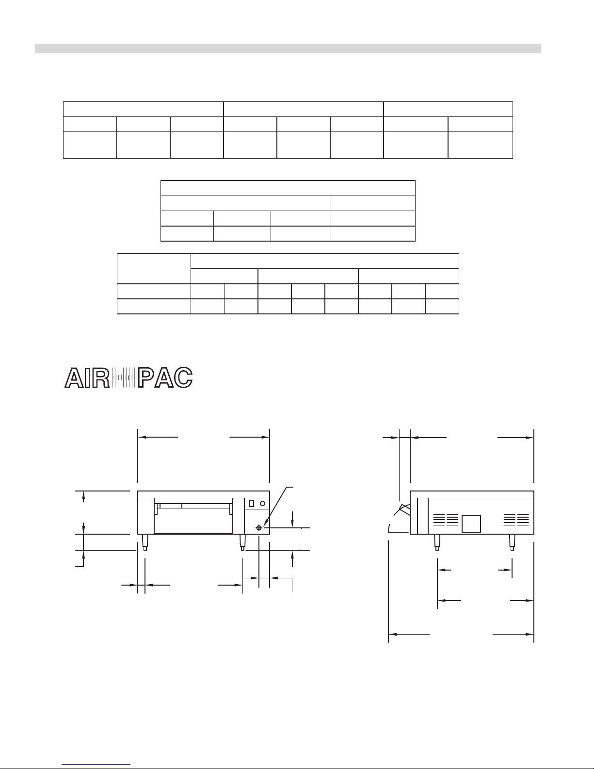
DIMENSIONS AND SPECIFICATIONS, MODELS AP1 & AP-A
36-1/2"
[927mm]
27"
[686mm]
2"
[51mm]
34-1/4"
[870mm]
3"
[76mm]
20-3/4"
[527mm]
26-3/4"
[679mm]
40-1/4"
[1022mm]
DOOR OPEN
3"
[76mm]
12"
[305mm]
REAR
CABLE
ENTRANCE
4-1/2"
[114mm]
6-1/4"
[159mm]
AIR
PAC
Oven Interior Dimensions* Exterior Dimensions Shipping Weight Lbs./Kg
Width Height Depth Width Height Depth Crated Uncrated
19-1/4”
(489mm)
4-3/4”
(121mm)
*With rack in place Two xed rack positions: 1-1/8” (28mm) and 1-5/8”(41mm)
17-3/4”
(451mm)
Combustible Wall Clearance Entry Clearance
Left Right Rear Crated
0” (0mm) 6” (152mm) 6” (152mm) 32” (813mm)
36-1/2”
(927mm)
Instillation Notes
16-1/2”
(419mm)
34-1/4”
(870mm)
230/104 140/64
Electrical
Requirements
Total kW 208V 240V X Y Z X Y Z
5.2 25 21.7 17 10 17 15 9 15
208 VAC = 197 VAC to 219 VAC 240 VAC = 220 VAC to 252 VAC
Single Phase 208V/3 Phase 240V/3 Phase
Nominal Amperes Per Line
Part # 1382636 Rev 5 (01/25/08)Page 4
Page 5

DIMENSIONS AND SPECIFICATIONS, MODEL AP4
36-1/2"
[927mm]
3"
[76mm]
34-1/4"
[870mm]
20-1/4"
[514mm]
DECK
30-1/4"
[768mm]
DECK
40-1/4"
[1022mm]
DECK
50-1/4"
DECK
6"
[152mm]
7-1/2"
[191mm]
7"
[178mm]
40"
[1016mm]
16-1/4"
[413mm]
2"
[51mm]
6-1/2"
[165mm]
OPEN SHELF
AREA
ADJUSTABLE
CASTERS
28"
[711mm]
REAR
CABLE
ENTRANCE
10.4KW
EACH
3"
[76mm]
REAR CABLE
ENTRANCE
TO RANGE
64-1/4"
[1632mm]
TO
65-3/4"
RANGE
10"
[254mm]
AIR
PAC
Oven Interior Dimensions* Exterior Dimensions Shipping Wt. Lbs./Kg
Width Height Depth Width Height Depth Crated Uncrated
19-1/4”
(489mm)
4-3/4”
(121mm)
17-3/4”
(451mm)
36-1/2”
(927mm)
64-3/4” to 66”
(1145mm) to (1676mm)
34-1/4”
(870mm)
*With rack in place Two xed rack positions: 1-1/8” (28mm) and 1-5/8”(41mm)
Installation Notes
Combustible Wall Clearance Entry Clearance
Left Right Rear Crated Uncrated
0” (0mm) 6” (152mm) 6” (152mm) 44” (1118mm) 35" (889mm)
800/363 650/295
Electrical
Requirements
kW Loading
208V/240V
208V 240V
L1 L2 L3 L1 L2 L3
Three Phase Nominal Amps Per Line
Two Circuits
Per Two Decks
20.8 Total
10.4 (per 2 Decks)
34 19.6 34 29.4 17 29.4
** Canada - 1 Circuit Only 20.8 Total (per 4 Decks) 68 39.2 68 58.8 34 58.8
** - Per CEC Part 1 2006, 26-744
Part # 1382636 Rev 5 (01/25/08) Page 5
Page 6

INTRODUCTION
Periodic inspections by your dealer or a qualied service
agency are recommended.
We suggest installation, maintenance and repairs should be
performed by your local authorized service agency listed
in your information manual pamphlet, or you may call the
factory at 1-800-424-2411.
INSTALLATION
Clearances
The clearance from combustibles on the AP1 & AP4 is six (6”)
inches, (152mm) on the right and rear side and zero (0”) on
the left. It is recommended that there be six (6”) (152 mm) of
clearance on the right side for fuse panel access.
Location
Proper placement of the oven will ensure operator and
satisfactory performance. Adequate clearance must be
provided for servicing, ventilation (if applicable), and
proper operation. The oven must be kept free and clear of
combustible material.
WARNING Control components may experience reduced
life if exposed to high temperatures. We recommend not
exposing control areas to temperatures above 140 degrees
Fahrenheit for a continuous period of time. For this reason,
care must be taken on installation to allow air ow around
units, especially when placed near other heat producing
sources. We recommend 6” (152 mm) spacing to the control
side of oven from other heat producing sources.
Installation for Ovens Equipped with Legs
Rating Plate
When corresponding with the factory or your local
authorized factory service center regarding service problems
or replacement parts, be sure to refer to the particular unit
by the correct model number (including the prex and sux
letters and numbers) and the warranty serial number. The
rating plate axed to the unit contains this information.
Installation for Ovens Equipped with Casters
It is recommended that in the use of casters a strain relief be
installed on the appliance. This will prevent any excess strain
on the terminal connection if the appliance is rolled out for
cleaning or servicing.
The front casters of the unit are equipped with brakes to
limit the movement of the oven without depending on the
connector and any quick disconnect device or its associated
wiring to limit the appliance movement.
Please be aware, there is a restraint on the unit and if
disconnection of the restraint is necessary, be sure to
reconnect the restraint after the oven has been returned to
its originally installed position.
Stacking Instructions
To Stack APA on top of an AP1 Unit
WARNING The maximum number of units to be stacked is
two additional units on top of the single base unit.
WARNING DISCONNECT ALL WIRING AND PLUGS FROM
ELECTRICAL SOURCE.
The AP1 counter unit is shipped with four (4) legs. This unit
is stackable up to three (3) units. The AP1 is considered the
base appliance and the APA is the stacking appliance.
WARNING: The base of counter appliance must be installed
with minimum 4” legs. The base appliance needs air
ow from the bottom for proper operation and is a NSF
requirement.
CAUTION: DO NOT LAY UNIT ON SIDES OR TOP.
Items required to complete stacking procedure:
1 – AP1 oven with top and legs.
1 or 2 APA ovens without top and legs.
Phillips screwdriver
7/16” open end wrench.
Part # 1382636 Rev 5 (01/25/08)Page 6
Page 7

OFF
Garland
1
2
3
8
9
7
4
5
6
INSTALLATION Continued
Assembly Instructions
1. Remove the back covers #5 from all units.
2. Remove the side panel #4 and the panel from the control
box #1.
3. Remove the front covers #3 and #2 from all units. The
door must be opened to remove these screws.
4. The top should lift o of the base unit. Set the top aside.
10. Do the same to the adjoining bottom bolt of the top unit.
11. Attach the stacking ange between the two loosened
bolts.
12. Repeat this process for an additional unit if desired.
13. Setting top #6 on the top unit.
14. Attach all side and rear panels, all front covers.
Ventilation
WARNING Do not place any obstruction on the top of the
appliances’ vent hold. Inadequate ventilation may result in
high ambient temperature at the rear of the oven. Excessive
ambient temperature can cause tripping of the blower motor
thermal overload protection device. This condition must be
corrected immediately to avoid damage to the blower motor.
Electrical Connections
The AP1, APA and AP4 are not supplied with any type of
cord and plug. Before attempting the electrical connection,
the rating plate should be checked to ensure that the
unit’s electrical characteristics and the supply electrical
characteristics agree.
Installation of the wiring must be made in accordance
with the applicable codes: National Electrical Code (for
US Installations), and Canadian Electrical Code Part 1 (for
Canadian Installations). For Canadian Installations, cooking
appliances shall have only one point of connection for power
supply.
5. Place the rst AP-A unit to be stacked on top the base
unit.
6. Loosen the top left and top right hex head bolt of the
base unit front frame #8. Do not remove.
7. Loosen the bottom left and bottom right hex head
bolt used to attach the front frame #8 of the unit to be
stacked.
8. Find two pieces of the stacking ange #7. Insert the
ange behind the head of each loosened bolt so as the
ange will join the two units together. The ange of the
stacking ange should point to the rear of the units.
9. Loosen the top hex head bolt used to attach the left rear
side panel mount #9 to the oven.
Part # 1382636 Rev 5 (01/25/08) Page 7
1. Switch panel size.
2. Overload protection.
3. Wire type.
4. Wire size.
5. Temperature limitations of the wires.
6. Method of connection (Cable, Conduit, etc.)
The service line enters through the rear of the unit and is to
be connected to the terminal block. Refer to wiring diagram
provided on the rear of the unit. Input voltage and phasing
must match the units voltage and phasing. Visual check all
electrical connections. Energize electric service to units.
Page 8

OPERATION
NOTE: Disconnect line cord from power supply before
cleaning or servicing.
Break-In Period
When oven is new, operate it for one hour at 450 degrees
before you begin your normal cooking operation. After
cooling, wipe the interior, including the racks, with a clean
damp cloth.
Start Up Procedure
After the appliance has been properly installed and a start up
performance check has been performed you are now ready
to start up the oven.
1. Inspect the oven interior for packing material.
2. Activate power switch (A) to “ON” position.
To Adjust Oven Temperature Set Point - Press “Up” arrow.
The top display will show “SP”, followed by current set point
temperature (blinks). Press “Up” or “Down” arrows to adjust
desired oven temperature. The display will return to actual
oven temperature after 2 seconds.
Timer Setting and Preset Adjustment – The timer display
will be blank when Timer is O. Press “Down” arrow once. “t1”
will display followed by ashing time setting (minutes). Press
“Up” or “Down” arrow to adjust to desired time. This time will
be saved as “t1”, which will be the preset. The display will go
blank after 5 seconds.
To Start Timer – Press the Timer Control button once to start
timer countdown. The timer will automatically start at the
Preset time. Press the Timer Control to turn timer o.
Temporary Timer Adjustment – If the timer setting is
altered while the timer is running, this setting will only apply
to the current cycle until the timer has run down. Preset “t1”
will not be aected.
Independent Top Burner Adjustment – Adjustment of
the top oven elements can be made by adjusting the dial
adjacent to the Oven Temperature Control. Example: If you
want to increase bottom browning you would reduce top
heat by turning dial to low (1), (1 – low, 6 – high). This will
not aect internal oven temperature.
At the end of the timed cycle, an audible buzzer will sound
for 3 seconds. NOTE: The timer only serves as a signal
function and does not control heating elements or oven
temperature in any way.
LED Indicators:
K1 - Yellow; indicates heating elements are on
K2 - Green; illuminated when timer is running
K3 - Red; illuminated when audible buzzer is on
Error Message Display:
If there is a fault with the oven temperature sensor, the
Temperature Display on the controller will indicate “199”
(ashing), and the audible buzzer may sound continuously.
Heating elements will be automatically disabled (by factory
default setting). Turn the appliance o and contact a service
person for further assistance.
Part # 1382636 Rev 5 (01/25/08)Page 8
Page 9

OPERATION Continued
K1 K2 K3
Timer Display
LED Indicators
Oven Temperature Controller
Oven
Temperature.
Set Point
Timer Control
CONCEPT OF AIR IMPINGEMENT COOKING
The “Air Pac” Oven produced by GARLAND COMMERCIAL
INDUSTRIES, INC., utilizes a revolutionary cooking concept,
called “AIR IMPINGEMENT”. It provides exceptional baked
food product quality in far less time than conventional
devices on the market. The “AIR IMPINGEMENT” system
directs a high velocity stream of heated air at the food
product being baked. This blast eect penetrates the
boundary layer of air encircling the product and heats the
food more eciently, because the air concentrates heat on
the food product. Greater heat transfer rates, which results in
products baking two to four times faster than conventional
means, are possible with “AIR IMPINGEMENT”.
The “AIR IMPINGEMENT” process develops the high velocity
air stream with a specially designed fan that draws superheated air from a heat source (electric elements). This air
is directed through a plenum chamber to patented “JET
PLATES” which have hundreds of focused jet ports that
“impinge” the heated air onto the food product surface. The
heated air is re-cycled to the heat source after striking the
food product, thus reducing energy consumption.
The “AIR IMPINGEMENT” process is tolerant enough for
sensitive food products and eects proper crisping and even
browning of such products as they pass through the oven,
because air is the medium which heats the food product.
Increase Value
Decrease Value
Part # 1382636 Rev 5 (01/25/08) Page 9
The “Air Pac” oven is supplied with one (1) wire rack that
has two positions. The optional rack that is a “Perf Rack”
that gives you the “ON THE DECK” type of baking. The two
position rack is used with the variable top heat control.
Page 10

COOKING CHART
Time and Temperature will vary depending upon load size and temperature, mixture and density or product. Use this guide to
develop your own cooking charts.
Italian Entrees
Product Temp. Time Load volume
Cheese Pizza 14” Par Baked Crust 525 5:10 1 Pizza Middle Baked on Pan
2 Topping Pizza Par Baked Crust 525 5:15 1 Pizza Middle Baked on Pan
3 Topping Pizza Deluxe, Multiple Toppings 525 5:30 1 Pizza Middle Baked on Pan
Cheese/Pepperoni 12” Pan 635 2:45 1 Pizza Middle Baked on Wire Rack
Sausage Deluxe 12” Pizza 635 2:55 1 Pizza Middle Baked on Wire Rack
Pepperoni 6” Pizza 635 2:45 2 Pizza Middle Baked on Wire Rack
Pepperoni 6” Pizza 635 2:45 3 Pizza Middle Baked on Wire Rack
16” Fresh Dough Pizza 475 7:30 1 Pizza Middle In Pan
16” Fresh Dough Pizza 475 6:30 1 Pizza Middle On Deck
16” Fresh Dough Pizza 475 7:00 1 Pizza Middle On Screen
12” Fresh Dough Pizza 525 5:30 1 Pizza Middle Baked on Pan
12” Fresh dough Pizza 525 5:30 1 Pizza Middle Fine Mesh Screen
12” Fresh dough Pizza 525 5:00 1 Pizza Middle On Deck
Lasagna 3 lbs. 550 15-17 min. 6x9 Pan Top Refrigerated Load Temp.
Stromboli 475 7-10 min. 13x18 pan Middle On Screen /Pan
Calzone 475 7-10 min. 2 Pieces Middle On Fine Mesh
Frozen Ravioli – (6) 400 18:00 6 Pieces Middle In Pan
Rack
Pos.
Comments
Meats and Poultry
Chicken Nuggets .5 oz 400 18 min. 3 Dozen Top Open Mesh Screen
Fresh Chicken (Breaded) 2-3 oz. llet 450 10 min 12-15 Top Open Mesh Screen
Frozen Chicken(Pre Breaded) .5 – 1 oz. 500 9 min. 18-24 Top Open Mesh Screen
Chicken Breast – 2 lbs. 400 25 min. One Middle Open Mesh Screen
Hot Dogs Wrapped in Crescent Rolls 375 7-8 min. 10 Top Baked on Pan
Seafood Entrees
Frozen Fish Sticks (Breaded) .4 oz 375 7 min. 4 Dozen Top Open Mesh Screen
Lobster Tail 550 3-5 min. 6 Middle Sautéed Dish/ Frozen
Lobster Scampi 550 3-5 min. 24/4 Servings Middle Sautéed Dish/ Frozen
Sautéed Scallops 550 3-5 min. 6 Servings Middle Sautéed Dish/ Frozen
Part # 1382636 Rev 5 (01/25/08)Page 10
Page 11

COOKING CHART Continued
Baked Potatoes & Rice
Product Temp Time Load Volume
Baked Potatoes 6 – 6 ½ oz. 400 35 min 20 Count Middle On Wire Rack
Baked Potatoes 6 – 6 ½ oz. 400 35 min. 10 Count Middle On Wire Rack
Baked Potatoes 8 lbs. of 16 oz. 400 45 min. 10 Count Middle On Wire Rack
Long Grain Rice 400 17 min.
1 Cup Rice,
2 Cups Water
Rack
Pos
Middle 2” Deep Pan
Comments
Baked Goods
Breadsticks 375 8 min. 8 Count Middle 13 x 18 Sheet Pan
Fresh Buttermilk Biscuits 400 14-15 min. 14-16 count Top 13 x 18 Sheet Pan
Biscuits Frozen Ready Bake 425 17 min. 16 Count Middle 13 x 18 Sheet Pan
White Cake Dry Mix 325 20 mi. 3 Pounds Middle 13 x 18 Sheet Pan
Cornbread 325 8-10 min. Middle 4x8 Pan
Chocolate Chip Cookies 1 oz. 325 12-Nov 18 Count Middle 13x18 Pan /Frozen
Sugar Cookies 1 oz. 325 11-12 min. 18 Count Middle 13x18 Pan /Frozen
Oatmeal Chip Cookies 350 11 min. 18 Count Middle 13x18 Pan /Frozen
Plain Muns 2.5 oz. 325 8-9 min. 12 count Middle In Liner Cup
Apple Cinnamon Muns 3 oz. 2-3/4 dia. 400 9 min. 12 Count Middle Heavy Wall Pan
Blueberry Muns 400 10-11 min. 12 count Middle Heavy Wall Pan
Banana Nut Muns 2.5 oz. 3-1/2 dia. 400 10-11 min. 12 Count Middle Heavy Wall Pan
Frozen Apple Pie 40 oz 375 30-35 min. Middle Frozen
Frozen Cherry Pie 46 oz.. 375 30-35 min. Middle Frozen
Cinnamon Sweet Reg. Roll 375 7 min. 8 Count Top 9” Round Pan
Dinner Rolls 400 4-5 min. 24 count Top 13x18 Sheet Pan
Crescent Rolls Reg. 375 6-7 min. Top 13x18 Sheet Pan
Part # 1382636 Rev 5 (01/25/08) Page 11
Page 12

 Loading...