

Page 1
SERVICE MANUAL
MODUL-LINE
BUILT-IN INDUCTION COOKERS
A
T
T
I
I
O
N
N
A
S
86037
C
CM
L
D
I
S
E
T
MODEL: IN/MO 7000
GARLAND COMMERCIAL INDUSTRIES
185 East South Street
Freeland, Pennsylvania 18224
Phone: (570) 636-1000
Fax: (570) 636-3903
Part # 4526029 (02/22/11) © 2008 Garland Commercial Industries, Inc.
Part # 4526029 (02/22/11) Page 1
GARLAND COMMERCIAL RANGES, LTD.
1177 Kamato Road, Mississauga, Ontario L4W 1X4
CANADA
Phone: 905-624-0260
Fax: 905-624-5669
Enodis UK LTD.
5E Langley Business Centre
Station Road, Langley SL3 8DS Great Britain
Phone: 01753 485900
Fax: 01753 485901
Page 2

Part # 4526029 (02/22/11)Page 2
Page 3

TABLE OF CONTENTS
SECTION 1 – REQUIREMENTS . . . . . . . . . . . . . . . . . . . . . . . . . . . . . . . . . . . . . . . . . . . . . . . . . . . .4
Authorized Personnel . . . . . . . . . . . . . . . . . . . . . . . . . . . . . . . . . . . . . . . . . . . . . . . . . . . . . . . . . . . . . . . . . . . . . . . . . . . . 4
“Operation Instructions“ Knowledge . . . . . . . . . . . . . . . . . . . . . . . . . . . . . . . . . . . . . . . . . . . . . . . . . . . . . . . . . . . . . . 4
Knowledge Of Electronic Systems . . . . . . . . . . . . . . . . . . . . . . . . . . . . . . . . . . . . . . . . . . . . . . . . . . . . . . . . . . . . . . . .4
SECTION 2 – SYSTEM DESCRIPTION . . . . . . . . . . . . . . . . . . . . . . . . . . . . . . . . . . . . . . . . . . . . . .5
Block Schematic . . . . . . . . . . . . . . . . . . . . . . . . . . . . . . . . . . . . . . . . . . . . . . . . . . . . . . . . . . . . . . . . . . . . . . . . . . . . . . . . . 5
Voltage Supply . . . . . . . . . . . . . . . . . . . . . . . . . . . . . . . . . . . . . . . . . . . . . . . . . . . . . . . . . . . . . . . . . . . . . . . . . . . . . . . . . . . 6
Power Board . . . . . . . . . . . . . . . . . . . . . . . . . . . . . . . . . . . . . . . . . . . . . . . . . . . . . . . . . . . . . . . . . . . . . . . . . . . . . . . . . . . . . 6
Control unit . . . . . . . . . . . . . . . . . . . . . . . . . . . . . . . . . . . . . . . . . . . . . . . . . . . . . . . . . . . . . . . . . . . . . . . . . . . . . . . . . . . . . . 6
Display . . . . . . . . . . . . . . . . . . . . . . . . . . . . . . . . . . . . . . . . . . . . . . . . . . . . . . . . . . . . . . . . . . . . . . . . . . . . . . . . . . . . . . . . . . 6
Error Messages . . . . . . . . . . . . . . . . . . . . . . . . . . . . . . . . . . . . . . . . . . . . . . . . . . . . . . . . . . . . . . . . . . . . . . . . . . . . . . . . . . . 7
SECTION 3 – INITIAL OPERATION. . . . . . . . . . . . . . . . . . . . . . . . . . . . . . . . . . . . . . . . . . . . . . . . .8
Function control . . . . . . . . . . . . . . . . . . . . . . . . . . . . . . . . . . . . . . . . . . . . . . . . . . . . . . . . . . . . . . . . . . . . . . . . . . . . . . . . . 8
Display . . . . . . . . . . . . . . . . . . . . . . . . . . . . . . . . . . . . . . . . . . . . . . . . . . . . . . . . . . . . . . . . . . . . . . . . . . . . . . . . . . . . . . 8
Pan Detection . . . . . . . . . . . . . . . . . . . . . . . . . . . . . . . . . . . . . . . . . . . . . . . . . . . . . . . . . . . . . . . . . . . . . . . . . . . . . . . 8
Power . . . . . . . . . . . . . . . . . . . . . . . . . . . . . . . . . . . . . . . . . . . . . . . . . . . . . . . . . . . . . . . . . . . . . . . . . . . . . . . . . . . . . . . 8
Fan. . . . . . . . . . . . . . . . . . . . . . . . . . . . . . . . . . . . . . . . . . . . . . . . . . . . . . . . . . . . . . . . . . . . . . . . . . . . . . . . . . . . . . . . . . 8
SECTION 4 – TROUBLE SHOOTING AND REPAIRS . . . . . . . . . . . . . . . . . . . . . . . . . . . . . . . . . .9
Trouble Shooting . . . . . . . . . . . . . . . . . . . . . . . . . . . . . . . . . . . . . . . . . . . . . . . . . . . . . . . . . . . . . . . . . . . . . . . . . . . . . . . . 9
Error-Code. . . . . . . . . . . . . . . . . . . . . . . . . . . . . . . . . . . . . . . . . . . . . . . . . . . . . . . . . . . . . . . . . . . . . . . . . . . . . . . . . . . 9
Additional Errors. . . . . . . . . . . . . . . . . . . . . . . . . . . . . . . . . . . . . . . . . . . . . . . . . . . . . . . . . . . . . . . . . . . . . . . . . . . . 11
Repair Of Problems . . . . . . . . . . . . . . . . . . . . . . . . . . . . . . . . . . . . . . . . . . . . . . . . . . . . . . . . . . . . . . . . . . . . . . . . . . . . .12
Adjustments . . . . . . . . . . . . . . . . . . . . . . . . . . . . . . . . . . . . . . . . . . . . . . . . . . . . . . . . . . . . . . . . . . . . . . . . . . . . . . . . . . . .14
Generator Type . . . . . . . . . . . . . . . . . . . . . . . . . . . . . . . . . . . . . . . . . . . . . . . . . . . . . . . . . . . . . . . . . . . . . . . . . . . . . 14
Pan detection. . . . . . . . . . . . . . . . . . . . . . . . . . . . . . . . . . . . . . . . . . . . . . . . . . . . . . . . . . . . . . . . . . . . . . . . . . . . . . . 14
Power . . . . . . . . . . . . . . . . . . . . . . . . . . . . . . . . . . . . . . . . . . . . . . . . . . . . . . . . . . . . . . . . . . . . . . . . . . . . . . . . . . . . . . 14
Repair by Garland . . . . . . . . . . . . . . . . . . . . . . . . . . . . . . . . . . . . . . . . . . . . . . . . . . . . . . . . . . . . . . . . . . . . . . . . . . . . . . .14
SECTION 5 – APPENDIX. . . . . . . . . . . . . . . . . . . . . . . . . . . . . . . . . . . . . . . . . . . . . . . . . . . . . . . . .15
Internal Connections . . . . . . . . . . . . . . . . . . . . . . . . . . . . . . . . . . . . . . . . . . . . . . . . . . . . . . . . . . . . . . . . . . . . . . . . . . . . 15
Recti er Circuit Board C014. . . . . . . . . . . . . . . . . . . . . . . . . . . . . . . . . . . . . . . . . . . . . . . . . . . . . . . . . . . . . . . . . . 15
CPU-Circuit Board C018 . . . . . . . . . . . . . . . . . . . . . . . . . . . . . . . . . . . . . . . . . . . . . . . . . . . . . . . . . . . . . . . . . . . . . 16
Power Circuit Board C026 . . . . . . . . . . . . . . . . . . . . . . . . . . . . . . . . . . . . . . . . . . . . . . . . . . . . . . . . . . . . . . . . . . . 17
Transformer . . . . . . . . . . . . . . . . . . . . . . . . . . . . . . . . . . . . . . . . . . . . . . . . . . . . . . . . . . . . . . . . . . . . . . . . . . . . . . . . 18
Recti er And Transistor Module . . . . . . . . . . . . . . . . . . . . . . . . . . . . . . . . . . . . . . . . . . . . . . . . . . . . . . . . . . . . . 18
Part # 4526029 (02/22/11) Page 3
Page 4

SECTION 1 – REQUIREMENTS
Authorized Personnel
The operator has to insure that all installation, maintenance
and inspection work is carried out by authorized and
quali ed personnel who has done a training course at Inducs
Ltd.
“Operation Instructions“ Knowledge
In order to do service work on an induction generator,
the operator must have an extended knowledge of the
“Operating Instructions“.
Knowledge Of Electronic Systems
The service- and maintenance operator must have
knowledge of the following components :
• Diodes
• Z-Diodes (Zener-Diodes)
• Recti ers (2phases and 3phases)
• Power transistor (IGBT)
The operator must know how to measure the electric
potential, current and resistors by means of a digital
multimeter. He also has to know how to check diodes with a
diodes tester.
Part # 4526029 (02/22/11)Page 4
Page 5
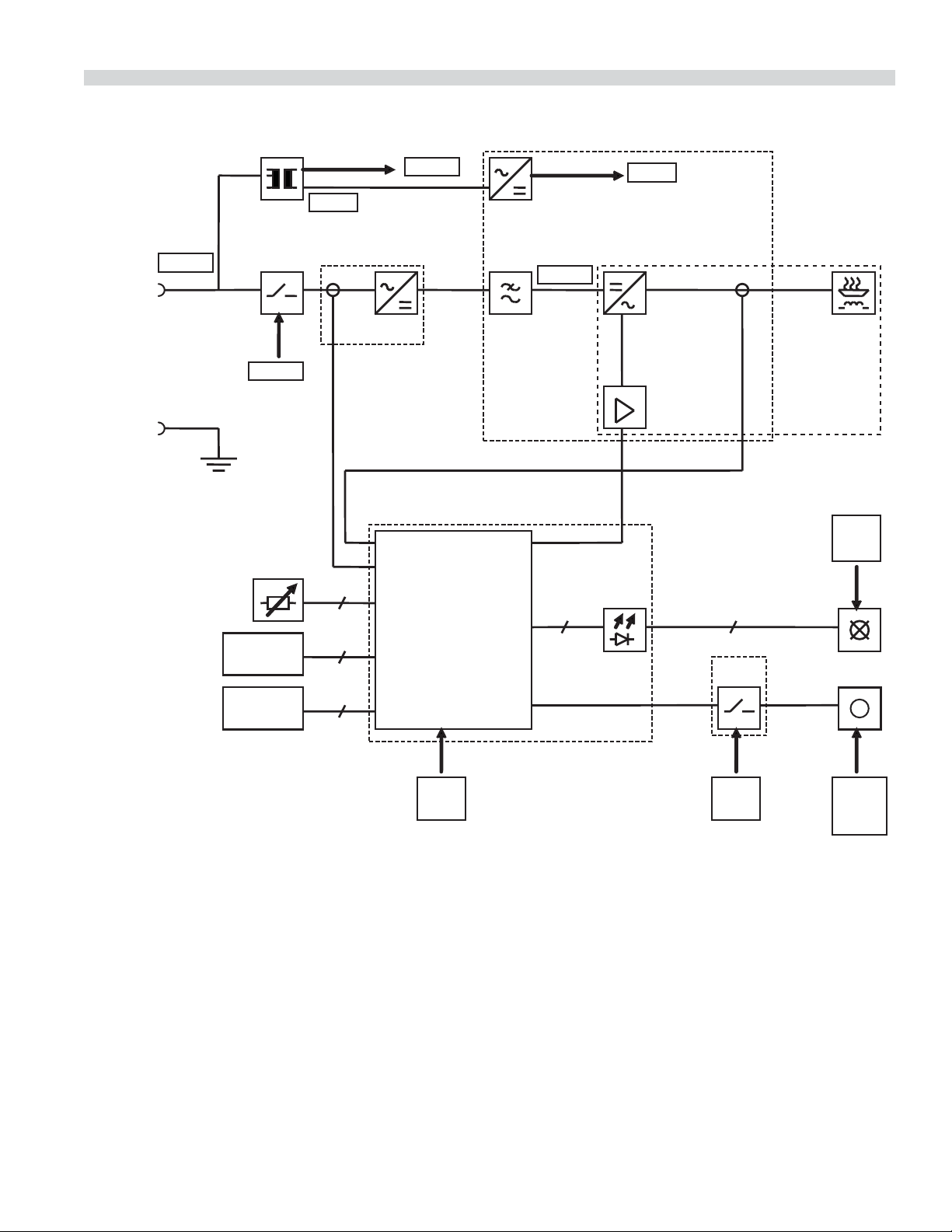
SECTION 2 – SYSTEM DESCRIPTION
Block Schematic
L1,L2,L3
PE
208VAC
230VAC
heatsink
23VAC
ST5
ST2/3,4
4
ST4
CPU
4
ST6
c014
230VAC
ST1
lter coil
300VDC
8
ST1
24VDC
ST8
c026
1x,2x,3x,4 x
LED
24VDC
5
c014
coil
4
ST7
ST1/1,4
supply
24VDC
ST2/1,2
c018
Relay
24VDC
M
fan
230VAC
Part # 4526029 (02/22/11) Page 5
Page 6

Voltage Supply
• Coil temperature
The power board voltage supply is wired with the power
contactor. On starting the generator, voltage is supplied to
the power board. The transformer is connected directly at the
entrance of the power supply. The transformer supplies two
di erent voltages: 230VAC for the power contactor and the
fan as well as 23VAC for the low voltage supply. The 23VAC
are changed on the circuit board C026 to 24VDC.
The following components are supplied with 24VDC:
• CPU-circuit board (C018)
• IGBT (C026)
• Fan relay (C014)
• External lamps
Power Board
As already stated, the power board is supplied by the power
contactor. The mains current is measured by a current
transformer, directly at the entrance of the 3-phases-recti er,
After the recti er there is a direct voltage of 300V. The
inductance that follows lters high frequency (EU) current .
• Ambient temperature
The power switch (IGBT), the fan as well as the display are
managed in response to these factors.
Display
Two elements are used for this display:
1. LED-group (LED1 - LED8) on the CPU-Circuit board (C018)
2. External lamps (24V), maximum 5 pieces
The ve external lamps are connected with the ve LED’s
(LED1-LED5). Please distinguish between operation lamps
and error lamps. The operation lamp shows what kind of
operation for the respective eld:
• Lamp out: Field is cut out
• Lamp ashes brie y Pan detection (pan is searched)
• Lamp ashes an error code: Error message (see Error
Messages table)
• Lamp continuously on: Power on
At the following power switch (IGBT) an alternating current
of approximately 20kHz is generated. This alternating current
(coil current) is transferred to the induction coil. At the exit
of the circuit board (C026), the coil current is measured by a
current transformer.
Control unit
The control unit is the heart of the generator. This is the CPUcircuit board (C018) with an integrated microprocessor which
manages the whole control system.
The following data are measured:
• Coil current
• Phases current
• Performance rate (Poti)
• Heat sink temperature (IGBT)
The error lamp indicates an error function.
LED1 to LED4 lead to external lamps on the outside, they are
used as operational lamps or as error lamps, depending on
the generator type. If an operation lamp or an error lamp is
shared by two elds (for example the surface covering this
induction type) the display can be overwritten from another
eld. As far as the error code display is concerned, the lower
eld has priority.
LED5 lead to the outside for an external lamp also. This is the
general error lamp for all elds all the time.
In an error, LED6 to LED8 show the error code, but only until
error code 7. If this happens in some errors, the lower eld
and the lower error code have priority.
Part # 4526029 (02/22/11)Page 6
Page 7

Error Messages
LED 8 LED 7 LED 6 Code Signi cation NOTE
————No error, normal function
— — On 01 No coil current, overdrive caused by non induction pan
— On — 02 High coil current, overdrive by non induction pan
— On On 03 Temperature heat sink too high
On — — 04 Temperature heating area (coil) too high 1
On — On 05 Potentiometer defected , wiring disconnected
On On — 06 Temperature inside the unit too high
On On On 07 Heating area – coil sensor short circuit 2
———08
———09
— — — 10 Communication error (serial interface)
———11
———12
———13
———14
———15
1. The induction unit can only be started again if the fault has been acknowledged (turn power
rotary knob “o “)
2. The induction unit continues working but the temperature of the cooking platform is not
controlled anymore.
Part # 4526029 (02/22/11) Page 7
Page 8

SECTION 3 – INITIAL OPERATION
Function control
To check the function controls, the induction generator must
be totally connected.
Display
1. The external lamps must be checked.
2. The operation lamp ashes if a coil is not used (Searching
function).
3. This procedure must be repeated for every coil.
Pan Detection
To check the pan detection, two pans are needed: one with a
diameter of 8cm (3”) and the other with a diameter of 12cm
(4.75”) .Only the pan with a diameter of 12cm (4.75”) should
be detected. A coil should not start operation when it is not
being used.
This procedure must be repeated for every coil.
Power
Place an “induction ready” pan with a diameter of 22-24cm
(8.5”-9.5”) onto the coil. Measure the generator power
at maximum level. This should be at the nominal power
(tolerance +/- 10%). This procedure must be repeated for
every coil.
Fan
Place various pans on the coils and start the generator on
the highest level. After a few minutes the fan should start.
The fan is controlled by the temperature and starts when the
heat sink temperature is about 50ºC/122ºF.
Part # 4526029 (02/22/11)Page 8
Page 9

SECTION 4 – TROUBLE SHOOTING AND REPAIRS
This section includes a list of the main errors, their causes and the respective steps to correct.
Trouble Shooting
Error-Code
Problem Possible Cause Measure
Code No. No No W
No Normal operation
Compare on another
cooking platform and with
an induction type pan
Replace power circuit
M12
board
1 S01
No coil current
Hardware overcurrent
U10 Non induction type pan M10
U11 Coil defective M11 Check coil L
Power circuit board
U12
defective
E
L
2 S02
3 S03 Temperature heat sink U30
High coil current
Software overcurrent
U10 Non induction type pan M10
U12
U13
U14
U31 Dirty fan/heat sink M31 Clean fan L
U32 Fan defective M32 Check fan L
U33
U34 Sensor Heat sink defective M34
U14
Power circuit board
defective
Error on DIP-Switchadjustment on CPU
CPU-circuit board
defective
Air entrance/exit
obstructed
Recti er circuite board
defective
CPU-circuit board
defective
Compare on another
cooking platform and with
an induction type pan
Replace power circuit
M12
board
Check DIP-Switch
M13
adjustment
M14 Replace CPU-circuit board L
M30 Clear air transport E/L
Replace recti er circuit
M33
board
Check sensor and heat
sink
M14 Replace CPU-circuit board L
E
L
L
L
L
4 S04
5 S05
Legend: W = Who should complete “Measure” E = End user L = Supplier
Part # 4526029 (02/22/11) Page 9
Temperature cooking
platform
Operational control
Line break
U40 Empty cooking M40 Empty pan E
U41 Interruption of coil sensor M41 Check coil sensor L
Operational control
U50
defective
M50 Check operational control L
Page 10

Problem Possible Cause Measure
Code No. No No W
No Normal operation
6 S06 Inside temperature U60
U14
Ambient temperature too
high
CPU-circuit board
defective
Check ambient
M60
temperature
M14 Change CPU-circuit board L
L
7 S07
8 S08
9 S09
10 S10
11 S11
12 S12
13 S13
Cooking platform
Sensing element
Communication error
(Serial interface)
Sensing element
U70
Coil temperature
Short circuit
U100 Line break M100 Check connection L
U101
Operational control
defective
CPU- circuit board
U14
defective
M101 Replace operation L
Check coil sensing
M41
element
M14 Replace CPU-circuit board L
L
14 S14
15 S15
Legend: W = Who should complete “Measure” E = End user L = Supplier
Part # 4526029 (02/22/11)Page 10
Page 11

Additional Errors
Problem Possible Cause Measure
Code No. No No W
No Operation lamp is continuously “ON”
Cooking platform does not
S20
heat enough
U10 Non induction type pan M10
U200 1 phase is missing M200
U12 Power board defective M12
CPU-circuit board
U14
defective
Compare on another
cooking platform and with
an induction type pan
Check mains cable
connection
Replace power circuit
board
M14 Replace CPU-circuit board L
E
L
L
Cooking platform
S21
continuously on
maximum power
Empty cooking platform
S22
switches “on“
Little metallic objects are
S23
heated on the cooking
platform
No. Operation lamp ashes
Cooking platform does not
S24
heat at all
U220 Pan detection defective M220 Check pan detection L
U220 Pan detection defective M220 Check pan detection L
U240
U200 1 phase is missing M200
U220 Pan detection defective M220 Check pan detection L
U241 Short circuit on generator M241
Operational control
U50
defective
CPU-circuit board
U14
defective
Power circuit board
U12
defective
Pan too small (Diameter
less than 12cm, 4.75”)
M50 Check operational control L
M14 Replace CPU-circuit board L
Replace power circuit
M12
board
M240 Use appropriate pan E
Check connection of
mains cable
Replace or repair
generator
L
L
L
Legend: W = Who should complete “Measure” E = End user L = Supplier
Part # 4526029 (02/22/11) Page 11
Page 12

Problem Possible Cause Measure
Code No. No No W
No. Operation lamp and error lamp “OFF”
Unit does not heat, no
S25
reaction, contactor does
not work
U250
U251
Building’s power fuses
defective, error on
electrical transmission
Error on operational
control
M201 Check mains supply L
M251 Check operational control L
Building fuses blow when
S26
unit is switched on
Some cooking platforms
S27
do not heat
Unit does not heat, no
S28
reaction, no contactor
Legend: W = Who should complete “Measure” E = End user L = Supplier
U241 Short circuit in generator M241
U271 Generator defective M241
Error on DIP-Switch-
U13
adjustment on CPU
Repair or replace
generator
Repair or replace
generator
Check DIP-Switch
M13
adjustment
Repair Of Problems
Measure Activity Comment
M10 • Compare on another cooking platform and with an induction
type pan
M11 • Check connection of coil
• Check coil on line break
• Coil overheated (brown color change)
M12 • Change power circuit board
M13 • Check DIP-Switch adjustment on CPU-circuit board
M14 • Replace CPU-circuit board
M30 • Clear ventilation system
M31 • Clean fan
M32 • Connect fan directly at 230V
M33 • Change recti er circuit board
M34 • Measure heat-sink temperature sensor resistor
At 25º Celsius (77ºF) resistor will read 20kOhm
At 70º Celsius (158ºF) resistor will read 3,5kOhm
• Check short circuit to case
• For a test: short-out the sensor with a 20kOhm xed resistor
Check if the pan is appropriate to
induction cooking or not: use a
magnet.
Disconnect temperature sensor
L
L
L
M40 • Switch o unit, cool down and switch on again. Use a pan with
cold water
Switch o eld!
Part # 4526029 (02/22/11)Page 12
Page 13

Measure Activity Comment
M41 • Measure the resistance of coil temperature sensor resistor
at 25º Celsius (77º F) resistor will read 1kOhm
at 180º Celsius (356ºF) resistor will read 3,5kOhm
• Resistor is higher on a higher temperature (PTC-resistor)
• Replace sensor with a value less than 900Ohm
• For a test: Short-out the sensor with a 1kOhm xed RESISTER
M50 • Measure operational control or main power control switch with
potentiometer: Potentiometer is 10kOhm and linear
• On level “0”: resistor = 0 Ohm
• On maximum level resistance= 10kOhm
• Resistor is proportional (linear) to swing angle
M60 • Measure temperature inside the case
• Admissible ambient temperature: 0°C/32ºF to appr. 70°C/158ºF
• Check point is on the CPU-circuit board
M100 • Check connection cable for serial operational control and
CPU-circuit board
M101 • Change serial operational control
M200 • Check mains cable, perhaps one phase missing
• Check the building fuses
M220 • Disconnect ST2 on CPU-circuit board and measure resistance
between brown and blue,
Measured value: 200Ohm < R < 2kOhm
• Replace recti er circuit board
M240 • Use suitable pan material
• Test with a pan with a diameter of 24cm (4.75”)
M241 • Disconnect mains power supply
• Visually inspect : blackened cables, components or strip
conductors?
• Transistor module: measure internal diodes (UF = 0.4V)
• Recti er: measure internal diodes (UF = 0.5V)
• Control trafo: measure electric voltage
• Check power supply CPU-print +24V
CPU-circuit board ST1/1 and ST1/4 (24V +/- 1V)
Disconnect sensing element
Disconnect operational control
(Poti)
M251 • Check power switch on operational control
Part # 4526029 (02/22/11) Page 13
Page 14

Adjustments
2. Errors can occur after wrong adjustments
This induction unit has been correctly adjusted by the
manufacturer. Any adjustments have to be made with
caution. Please pay attention to the following points:
1. Note the original position of the poti’s: remember the
number of turns you make.
Switch Position
DIP-Switch for
generator type
0
1 ON
2ON
3ONON
4ON
5ONON
6ONON
7 ONONON
8ON
9ON ON
10 ON ON
11 ON ON ON
12 ON ON
13 ON ON ON
14 ON ON ON
15 ON ON ON ON
8765
3. Only small corrections can be made with adjustments
Generator Type
The generator type is adjusted in the binary code with the
DIP-switches 5 to 8 on the CPU-circuit board
Switch Power
Summary: software and generator type
The following list shows the number of types of the various
generators.
Please note the positions of the power switches from the
above table.
Typ e
MO/DU 7000, 208V 6 and 8 on
MO/DU 7000, 400V 5 and 8 on
DIP
Switch setting
Pan detection
The potentiometer on the recti er circuit board is used to
adjust the pan detection:
Turn clockwise: acceptance of smaller pans
Turn counterclockwise: only bigger pans are accepted
Power
Only one potentiometer per eld is available on the power
circuit board to adjust the power:
Turn clockwise: less power
Turn counterclockwise: more power
Repair by Garland
If the generator has to be repaired by the manufacturer,
please enclose an exact description of the error. If possible,
use the original package for the return. If it isn’t available,
do not use porous material for wrapping (like styropor). This
could enter the unit and the electronic parts and is di cult
to remove.
Part # 4526029 (02/22/11)Page 14
Page 15

SECTION 5 – APPENDIX
Internal Connections
Recti er Circuit Board C
View solder side
poti for pa n detector
9 10 11 12
230V Venti
Part # 4526029 (02/22/11) Page 15
Page 16

CPU-Circuit Board C
View components side
eld 4(8
eld 4(7
coil- eld 3(5
sensor eld 2(4
1k eld 2(3
heatsink- eld 3(5
sensor eld
20k eld 2(3
eld 3(6
eld 1(2
eld 1(1
eld 4(8
eld 4(7
eld 3(6
3(4
eld 1(2
eld 1(1
external temp'sensor
optinal
1 2
eld 4(8
eld 4(7
current- eld 3(5
meas. eld 2(4
signal eld 2(3
power- eld 3(5
control eld 2(4
(poti 10k)
RS485 (3
optional (2
3 Poti
optional
eld 3(6
eld 1(2
eld 1(1
eld 4(8
eld 4(7
eld 3(6
eld 2(3
eld 1(2
eld 1(1
DIP-Switch
1)
2)
3)
4) connection
5) to c026
6)
7)
8)
1)
2) connection
(4
(1
3) to c014
4)
1) lamp 1
2) lamp 2
3) lamp 3
4) lamp 4
5) lamp 5
6)
7)
8) +24VDC
Part # 4526029 (02/22/11)Page 16
Page 17

Power Circuit Board C
p
View components side
IGBT pre
drive
power
adjustment
eld 1
Connection
with
c018 –
logic board
current
measure
signal
POT1-4 und ST5
o
tional
power
adjustment
eld 2
IGBT pre
drive
Coil connection
eld 1
Coil connection
eld 2
Part # 4526029 (02/22/11) Page 17
Page 18

Tran sf orme r
supply transformer
for logic board
contactor ignition
and fan
Recti er And Transistor Module
-
+
L3
L2
L1
8
230VAC outlet (fan)
7
6
5
230VAC outlet (contactor ignition)
4
mains supply voltage
3
( 208V/ 230V / 400V AC)
2
1
23VAC outlet (logic supply)
+
C2/E1
E2
C1
C2/E1
3
2 1
solder side view
rectier board
C1
E2
solder side view
power board
Item 2: transistormodul IGBTItem . 1: rectier
Part # 4526029 (02/22/11)Page 18
Page 19

Part # 4526029 (02/22/11) Page 19
Page 20

 Loading...