

Garelick 79715 User Manual
Installation and Operation Instructions for
Commander Series Seat Hardware
Form 12.489
WARNING
AVOID SERIOUS OR FATAL INJURY DUE TO
ROTATION OF SEAT.
LOCK SWIVEL WHEN SPEED EXCEEDS 5 M.P.H.
OPERATION:
To Slide Seat:
Pull right rear knob out and slide seat to desired location. Release
knob; it will self lock in position.
To Swivel Seat:
45 Degree Auto Lock Mode Pull right knob out. Rotate seat to desired
location. Release knob; it will self-lock in position at 45 degree
increments.
Free Rotation Mode Pull right knob out and rotate the knob 90
degrees clockwise. Release knob. The seat will rotate freely. Rotate
knob 90 degrees counterclockwise to re-engage locking system.
To Adjust Seat Height:
Upward
Note: This adjustment must be made when the seat is unoccupied.
Loosen cam lock by pulling the handle outward. (Cam lock is located
on the outer tube with the handle in front).
Pull the height adjustment lever located on the left side upward.
The seat will rise. Release lever to lock-in desired position. It may be
necessary to assist the seat upward depending on the seat’s location
with respect to its fore and aft position.
Push cam lock handle back to its original position.
Downward
Loosen cam lock by pulling the handle outward. (Cam lock is located
on the outer tube with the handle in front.)
Pull the height adjustment lever located on the left side upward while
remaining seated. When the desired height is achieved, release the
lever. The seat will remain at that height.
Push cam lock handle back to its original position.
Refer to Figure 1A.
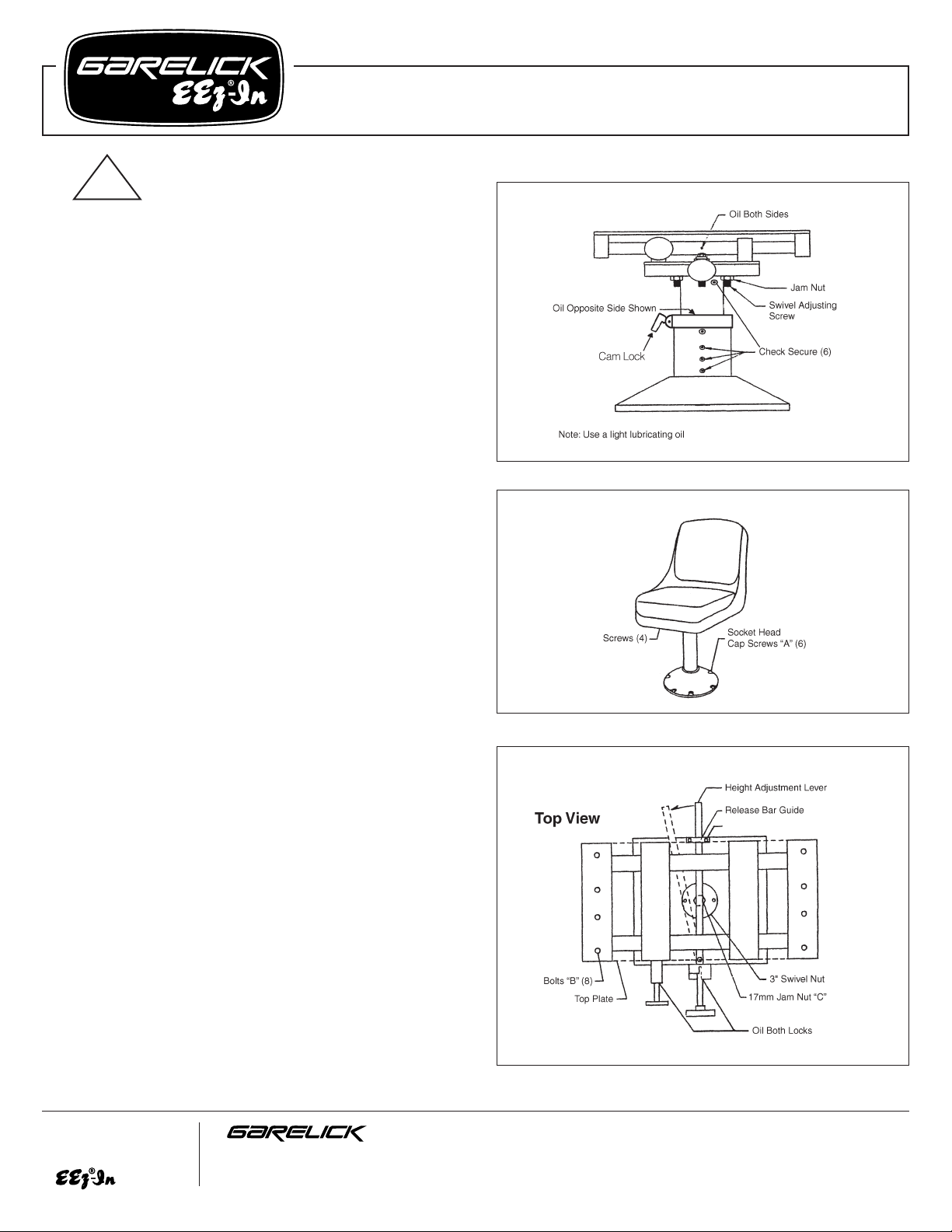
LUBRICATION:
For ease of operation, it is recommended that the horizontal slide
action and vertical rise action be periodically lubricated with a light
lubricating oil. Refer to Figure 1A and note three oil ports and the slide
and swivel locks in Figure 2.
MAINTENANCE:
As with all marine hardware installations, it is recommended that any
exposed fasteners be periodically inspected for security. Any loose
screws should be tightened with the appropriate tool.
Note: Clean only with warm soapy water. Never use harsh cleaners or
petroleum products.
FIG. 1
FIG. 2
Write for
a Complete
Catalog
Phone: 651-459-9795
PO Box 8, 644 2nd Street E-mail: mail@garelick.com
St. Paul Park, Minnesota 55071 On the Web: www.garelick.com
5/04
FIG. 1A
!
Screws “G”
Installation and Operation Instructions –
Commander Series Seat Hardware
Form 12.489
SWIVEL FRICTION ADJUSTMENT:
There are six adjusting screws to minimize seat swivel wobble. To
adjust, loosen Jam Nut using a 1/4” Allen Wrench. Turn screw until it
stops. Do not over tighten; light pressure is sufficient. Repeat for all six
screws. Check seat for ease of rotation. If seat is difficult to rotate, then
back screw off slightly and reset all Jam Nuts.
REMOVAL OF GAS SPRING:
Refer to Fig. 1.
1. Fully extend gas spring by pulling the cam lock handle out and
pulling the height adjustment lever UP. The seat will rise. Push the
cam lock handle in.
2. Remove seat from seat slide by removing 4 screws.
3. Remove slide assembly from detachable seat base plate by
removing [6] 3/8-16x1” socket head cap screws [A].
Refer to Fig. 2.
4. Remove slide top plate by unscrewing [8] 1/4-20x3/4” flathead
allen bolts [B].
5. Remove release bar guide by unscrewing [2] 1/4-20x1”
flathead allen screws [G], rotate height adjustment lever to
expose jam nut [C] located on gas spring shaft.
6. Remove 17mm jam nut [C].
NOTE: If jam nut and 3” swivel nut rotate in unison, tighten jam
nut so it will snug up the swivel. Then back off nut.
Refer to Fig. 3.
7. Tip unit on its side.
8. Remove cylinder mounting bracket by unscrewing [2] 1/420x1” flathead allen screws [D]. Unscrew gas spring assembly
by rotating it counterclockwise from the threaded end. Pull out
gas spring assembly.
Refer to Fig. 4.
9. Detach clevis or cylinder mounting bracket (depending on which
gas spring you have) from gas spring by removing hex bolt (E).
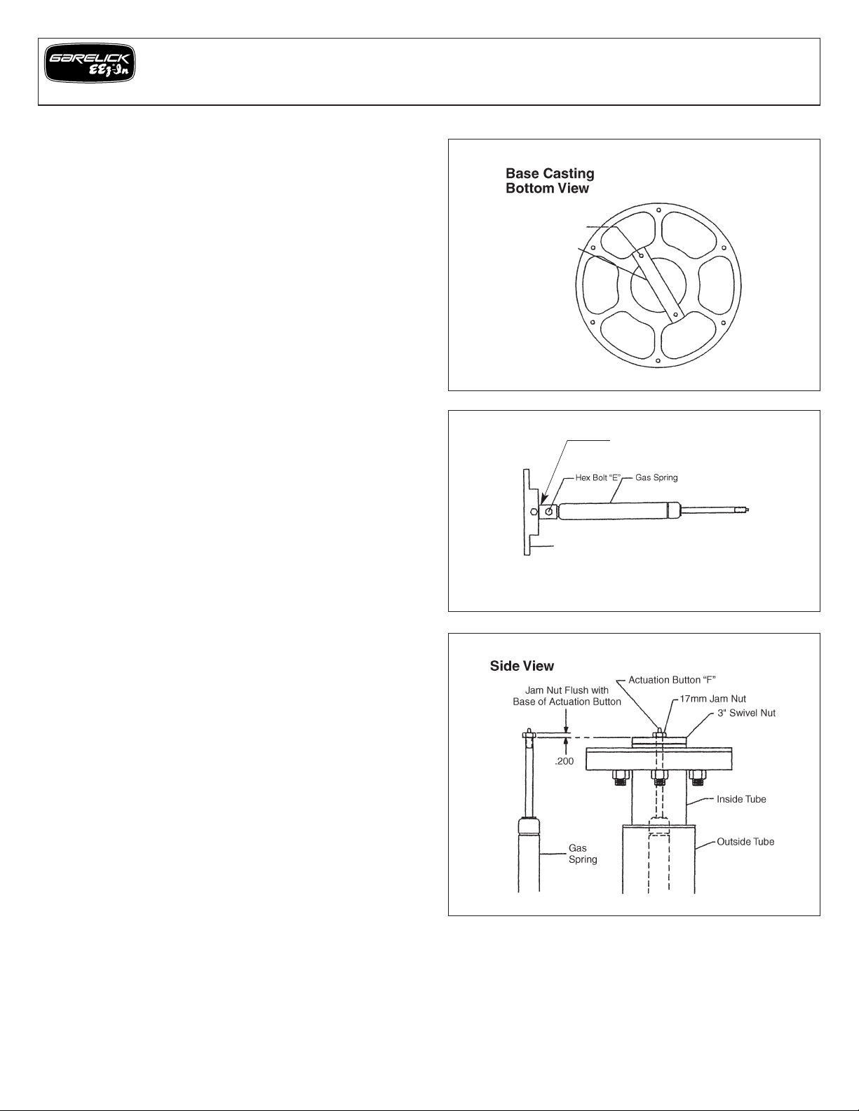
INSTALLATION OF GAS SPRING:
1. Attach gas spring to clevis or cylinder mounting bracket with hex
bolt.
Refer to Fig. 5.
2. Thread gas spring assembly into swivel nut so that the threads
are exposed approximately .2”. Thread jam nut onto gas spring
shaft until the top of the jam nut is flush with the base of the
actuation button [F].
3. Align cylinder mounting bracket and secure with [2] 1/4-20x1”
flathead allen screws.
4. Snug jam nut against 3” swivel nut. Rotate height adjustment
lever until centered over gas spring actuation button.
5. Check unit for proper function using height adjustment lever.
Make sure unit will lock at intermediate heights, if not readjust
cylinder.
6. Attach release bar guide with [2] 1/4-20x1” flathead allen
screws.
7. Replace the seat slide top plate and secure it in place with [8]
1/4-20x3/4” flathead allen screws.
8. Mount slide assembly on detachable seat base and secure with
[6] 3/8-16x1” socket head cap screws.
9. Reattach the seat.
FOR SPARE PARTS, PLEASE CALL CUSTOMER SERVICE
FIG. 4
FIG. 5
FIG. 3
Clevis
Cylinder Mounting Bracket
Allen Screws “D”
Cylinder Mounting
Bracket
 Loading...