

Garelick 75375 User Manual
Installation Instructions for
Portable Cockpit Tables
Models 75400, 75401, 75405, 75375
Form 12.476
Thank you for selecting our superior quality Garelick/EEz-In
Brand Portable Cockpit Table. Your table has been designed and
manufactured using the finest material, and was fabricated and
finished with boating in mind.
INSTRUCTIONS FOR 75400 SIDE MOUNT INSTALLATION
Hardware Required
(4) #10 stainless steel wood screws of suitable length
NOTE: Due to the variety of side coaming materials and
thicknesses used in boat construction, fasteners have not
been provided.
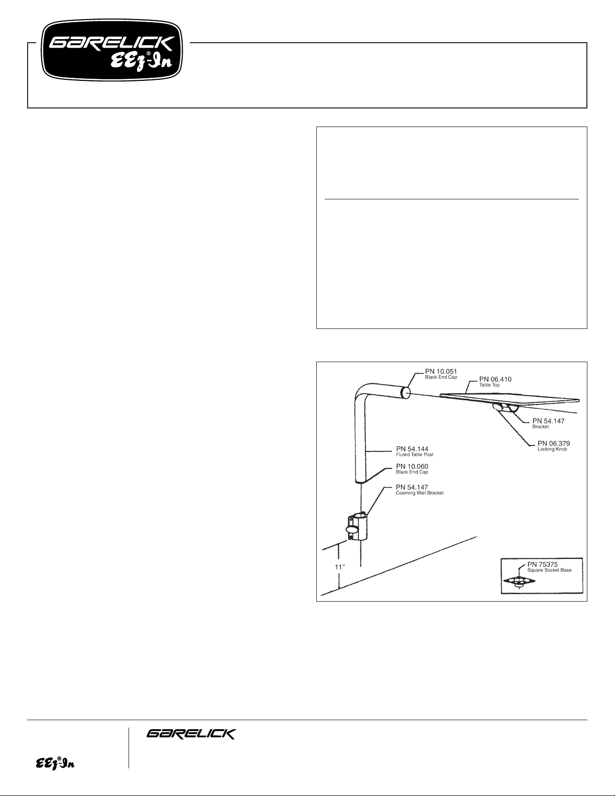
Refer to Fig. 1:
1. Determine your desired location of the table and coaming
wall bracket. For maximum stability, it is recommended
that the wall bracket be mounted approximately 11" up
from the deck floor. Make sure that the wall bracket is
perpendicular to the deck floor before marking four
mounting holes through the bracket and onto the side
coaming.
2. Drill four 1/16" diameter pilot holes. Fasten wall bracket
to coaming with selected fasteners.
3. Insert table leg into wall bracket. In the full down position,
table height will be approximately 26". Standard table
height is 31". Slide table onto horizontal portion of table
leg, level and secure in place with locking knob. Adjust
table to desired height and lock in position using side
coaming bracket locking knob.
(over)
Parts List
Refer to Fig. 1
Factory
Qty. Part No. Description
1 54.147 Coaming Bracket
1 54.144 2-1/4" Diameter Fluted Table Post
1 10.051 2-1/4" Diameter Black End Cap
1 10.060 2" Diameter Black End Cap
1 06.410 Table Top
1 75375 Square Socket Base
1 06.379 Locking Knob
FIG. 1
Write for
a Complete
Catalog
Phone: 651-459-9795
PO Box 8, 644 2nd Street E-mail: mail@garelick.com
St. Paul Park, Minnesota 55071 On the Web: www.garelick.com
2/00
INSTRUCTIONS FOR 75405/75375 DECK MOUNT
Hardware Required
(8) #14 stainless steel wood screws of suitable length
Refer to Fig. 2:
1. Determine desired location of table. Using the
square/round mount socket base as a template, mark eight
mounting hole locations. Find the center point of location
by scribing two lines diagonally between corner mounting
holes. The center point is where these two lines cross.
Scribe a 3-3/4" diameter circle around this center point.
NOTE: Make certain that the area under the floor directly
below the marked hole locations is free from
obstacles such as fuel tanks, hoses, electrical
wires, etc.
2. Use a 3-1/4" hole saw or a keyhole saw to cut out a
3-1/4" circle.
3. Drill eight 1/16" diameter pilot holes.
4. Secure socket base in place with selected fasteners.
5. Insert tapered end of table leg into socket base. Slide table
onto horizontal portion of table leg, level and secure with
locking knob (B).
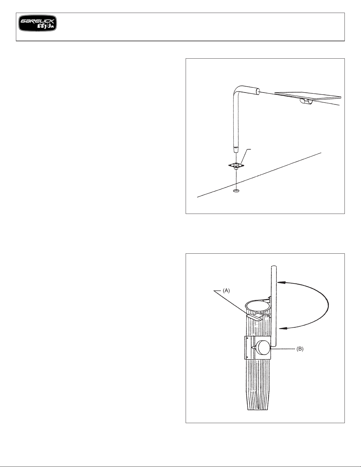
REMOVAL AND STOWAGE OF PORTABLE COCKPIT TABLE
Refer to Fig. 3
1. To rotate table top, loosen locking knob (A) until bracket
rotates freely, secure top by rotating to desired position
(horizontal or side).
2. To remove top, loosen locking knob until bracket rotates
freely, then slide top off for stowage.
3. To rotate table post:
• Model 75045 – To loosen table post, rotate while pulling
upward to either rotate or remove from the deck mount
socket base.
• Model 75400 – Loosen locking knob on wall coaming
bracket (B) until table post rotates freely. Slide table post
out for stowage, or rotate and reposition height before
tightening locking knob.
FIG. 2
FIG. 3
Installation Instructions –
Models 75400, 75401, 75405, 75375 Portable Cockpit Tables
Form 12.476
 Loading...