

Garelick 75350 User Manual
Installation Instructions for
Surface or Flush Mount Castings
Form 12.510
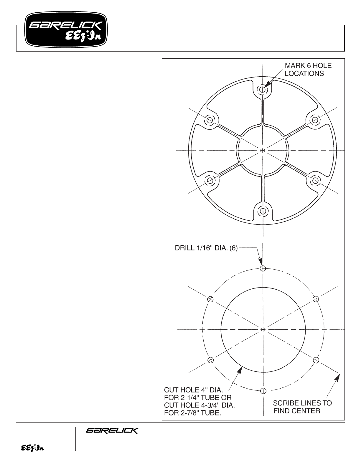
SURFACE MOUNT
HARDWARE REQUIRED
(6) #14 stainless steel wood screws
Refer to drawing at right:
1. Determine the desired location of the casting.
Using the casting as template, mark 6 mounting
hole locations.
2. Make certain the area under the deck directly
below the marked holes is free from obstacles
such as fuel tanks, hoses, electrical wires, etc.
3. Drill (6) 1/16" diameter pilot holes on the marks
from step 1.
4. Set casting in position and fasten in place with
selected fasteners.
5. Make sure socket is clean and insert tapered tube.
FLUSH MOUNT
HARDWARE REQUIRED
(6) #14 stainless steel wood screws
Refer to drawing at right:
1. Determine the desired location of the casting.
Using the casting as a template, turn it upside
down and lay it flat on the deck. Scribe/mark 6
hole locations for the mounting screws.
2. Remove the casting and find the center point of
the location by scribing diagonal lines between
hole locations that are opposite of each other.
Scribe 2 or 3 lines. Where these lines intersect is
the center of the mounting location.
3. Using the center point determined in step 2
above, scribe a 4" diameter circle if the casting is
for 2
1
⁄4" tubing; or a 43⁄4" circle if the casting is for
27⁄8" tubing.
4. Make certain the area under the floor directly
below the marked holes is free from obstacles
such as fuel tanks, hoses, electrical wires, etc.
5. Use a hole saw or keyhole saw to cut out the
scribed circle.
6. Drill (6) 1/16" diameter pilot holes on the marks
from step 1.
7. Set casting in position and fasten in place with
selected screws.
8. Make sure tapered socket is clean and insert
tapered tube.
Write for
a Complete
Catalog
Phone: 651-459-9795
PO Box 8, 644 2nd Street E-mail: mail@garelick.com
St. Paul Park, Minnesota 55071 On the Web: www.garelick.com
5/02
 Loading...