

Garelick 74003 User Manual
Assembly and Installation Instructions for
Tandem Seat Slide Models 74001, 74002, 74003
Form 12.507
ASSEMBLY INFORMATION
Read instructions thoroughly before starting assembly and
installation.
Because of the wide variety of possible installations, mounting
hardware is not supplied. Recommended fasteners should be
#14 or #16 stainless steel wood screws long enough to
penetrate approximately 3/4 to 7/8 of the thickness of the
seat substrate but not long enough to protrude through it as
they may cause injury if sat upon.
ASSEMBLY INSTRUCTIONS FOR 74001
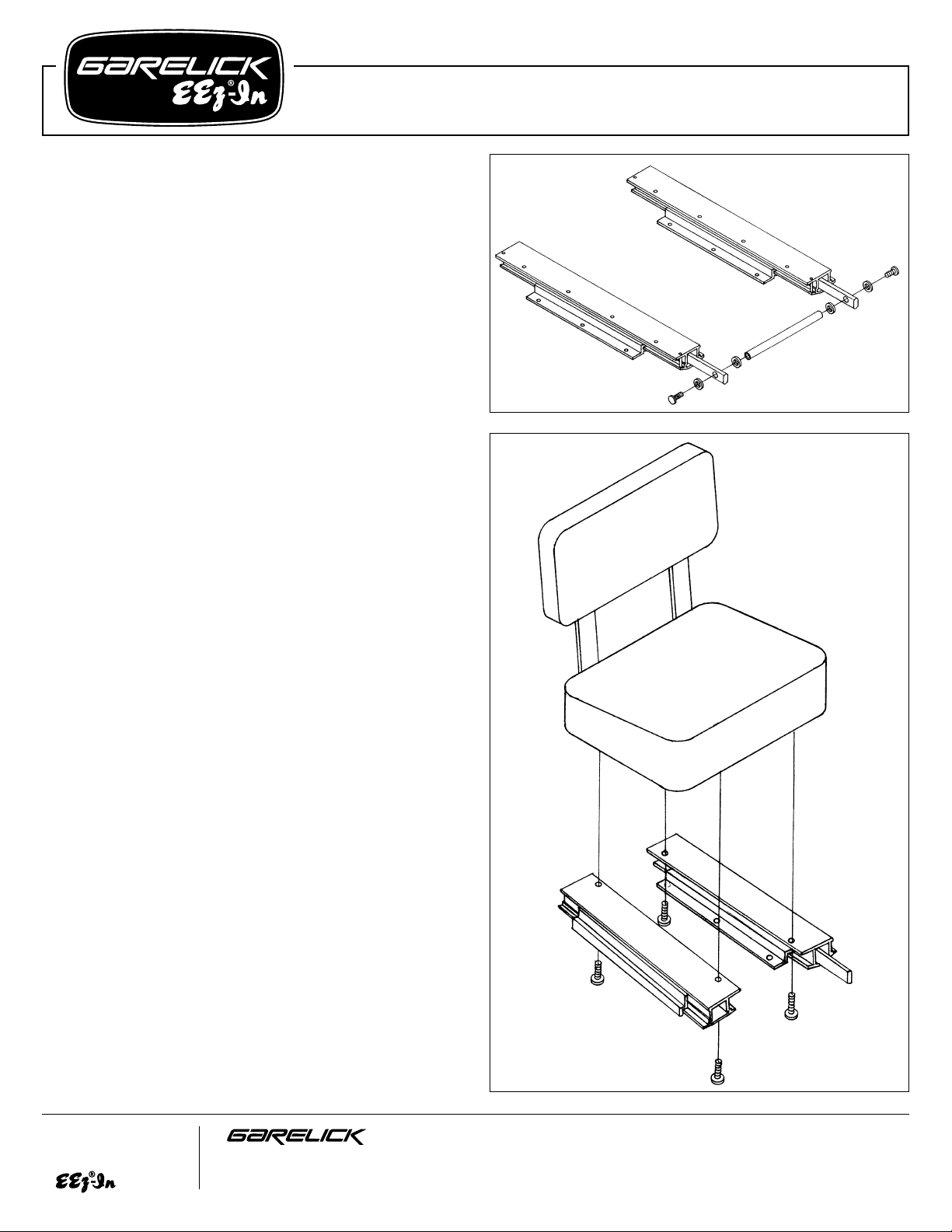
Refer to Fig. 1
1. Remove slide rails and cross bar from packaging. Remove
1 screw from each end of the cross bar.
2. Install the cross bar between the release handles of the
slide rails by placing one rubber washer on both sides of
each handle, aligning the holes and inserting a screw to
fasten into the ends of the cross bar. Do not over tighten as
the rubber must flex to allow for movement of the cross
bar.
ASSEMBLY INSTRUCTIONS FOR 74001, 74002, 74003
Refer to Fig. 2 and Fig. 3.
1. Turn the seat upside down to expose the seat bottom; center
seat slide rails left-to-right and front-to-back. For models
74002 and 74003 determine which side is preferred for
the release handle and then set the rails approximately 4"
in from each side of the seat. Use a tape measure to assure
that the rails are parallel to each other. This is critical to the
operation of the sliding action. Mark 3 or 4 holes in each
rail, depending on model of unit being installed, onto the
seat bottom.
2. Drill 6 or 8 pilot holes, depending on model of unit being
installed, of suitable size for the screws to be used. Fasten
rails to seat bottom finger tight. Measure between the rails
front and back to assure the rails are parallel before final
tightening of the screws. Record this measurement for
later reference.
3. Set the slide adjustment to the middle setting so there is
equal upper slide extrusion extending from either end of
the lower slide extrusion. Turn the seat right side up.
4. Determine the desired location for mounting the seat. If the
surface is covered in carpeting, place a piece of cardboard
or poster board over the area and secure with tape.
Position the seat in the desired location, keeping in mind
the seat will slide approximately 3” fore and aft. Mark the
4 outside comers of the lower slide extrusions on the
cardboard. Remove the seat and turn it upside down.
(over)
Write for
a Complete
Catalog
Phone: 651-459-9795
PO Box 8, 644 2nd Street E-mail: mail@garelick.com
St. Paul Park, Minnesota 55071 On the Web: www.garelick.com
1/02
FIG. 2
FIG. 1
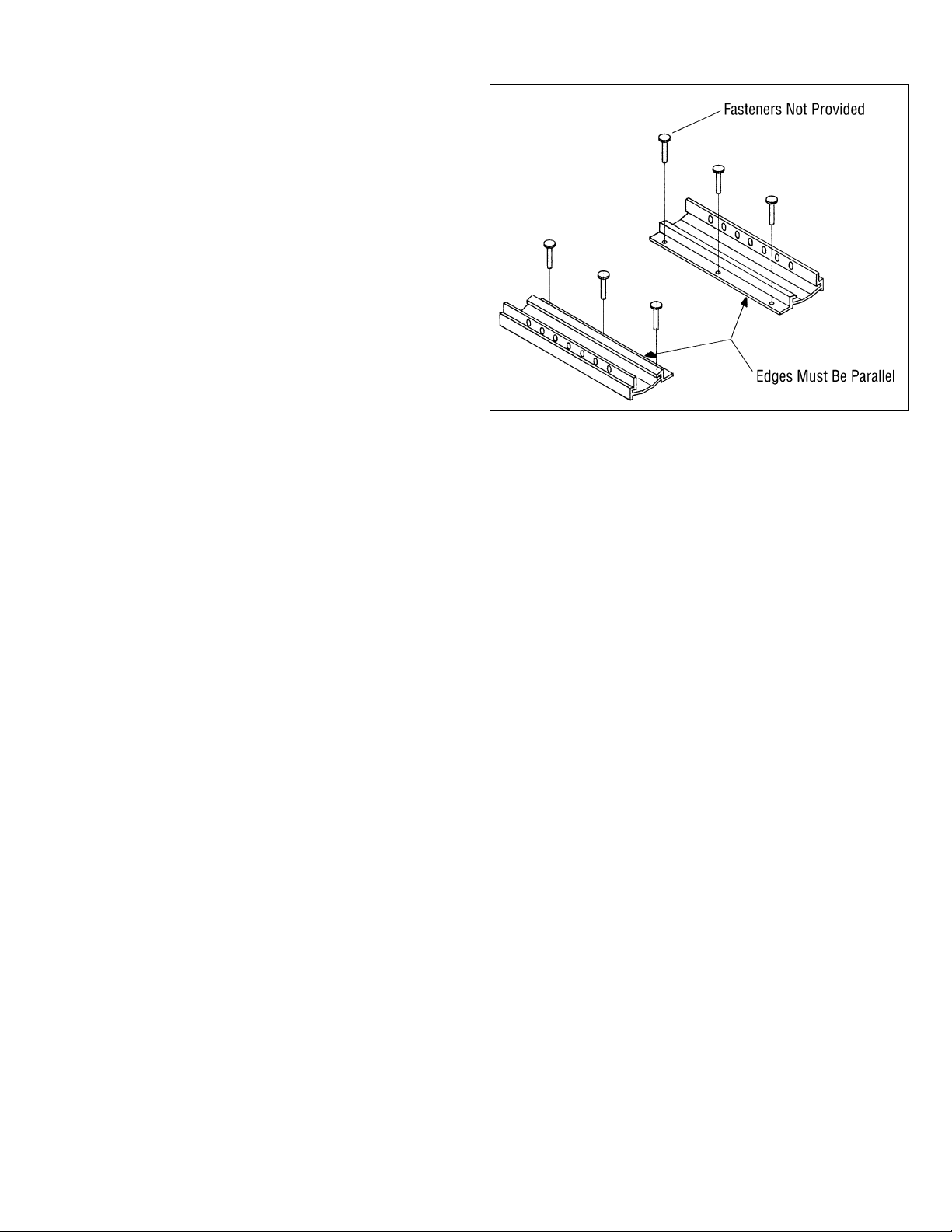
5. Make a mental note of which side of the lower slide
extrusion the mounting holes are on. Release the slide lock
handle and remove the lower slide extrusions by sliding
them in the direction opposite the release handle.
6. Place the lower slide extrusions within the 4 outside corner
marks on the cardboard, be sure the mounting holes are
on the correct side. Measure the distance between the rails
and confirm the dimension as the same measurement
recorded in step 2. Carefully mark the position of the 6
mounting holes so as not to move the rails out of position.
7. Drill 6 pilot holes of suitable size for the screws to be used.
Remove the cardboard or poster board and discard.
8. Fasten rails to the mounting surface. Continue checking the
rails for proper position using the measurement from step
2 before finishing tightening of screws. Remember, it is
critical that the rails remain parallel in order to slide. If
this instruction is not followed the slide will bind and not
slide freely.
9. Carefully line up seat and rails, slide seat into position from
front to back. The release handle will have to be in the
released position in order for full engagement of the rails.
10. Test the operation of the slide by sitting in the seat and
moving the release handle to the full left, push back with
your feet and the slide should move smoothly to the rear.
Pull forward and the slide should move forward. There
should be a slight resistance from the viscosity of the grease
but there should not be any binding. If the slide binds, then
the rails are improperly installed and need to be adjusted
as instructed in steps 6 through 8.
OPERATING INSTRUCTIONS
1. Sit in the seat with feet flat on the deck. Grasp slide lock
release handle and move it to the left until it stops. Push to
the rear with your feet and the slide will adjust to the rear.
Release the handle and the lock will automatically hunt for
the next stop position. There is a lock position every inch
for approximately 6" of adjustment. To adjust forward,
repeat the above procedure except to pull with your feet
and the slide will adjust forward. Release the handle and
the unit will find a stop position.
2. To maintain proper operation over time, it is recommended
that the slide rails and locking pin be lubricated
occasionally with a light grease. Lubricants have a
tendency to dissipate over time and as this happens the
slide will become difficult to operate. Use a light marine or
automotive grease and brush a thin coat on all
mating/sliding surfaces.
FIG. 3
 Loading...