

Garelick 71053 User Manual
Mounting and Operating Instructions for
Outboard Motor Bracket Models 71040, 71057,
71042, and Outboard Motor Bracket Adapter
Plate Model 71053
Form 12.109
OUTBOARD MOTOR BRACKET MOUNTING INSTRUCTIONS
(See reverse side for Adapter Plate Installation Instructions)
IMPORTANT INSTRUCTIONS
Check hardware pack contents for the following mounting
hardware:
4 - 5/16 x 3" stainless steel carriage bolts
4 - 5/16" stainless steel locknuts
1. These brackets are not recommended for use with 9.9
4-stroke motors.
2. Read instructions completely before starting assembly.
3. Motor bracket must remain in “UP” position throughout
installation.
4. DO NOT operate motor bracket unless motor is installed
on bracket.
MOUNTING INSTRUCTIONS
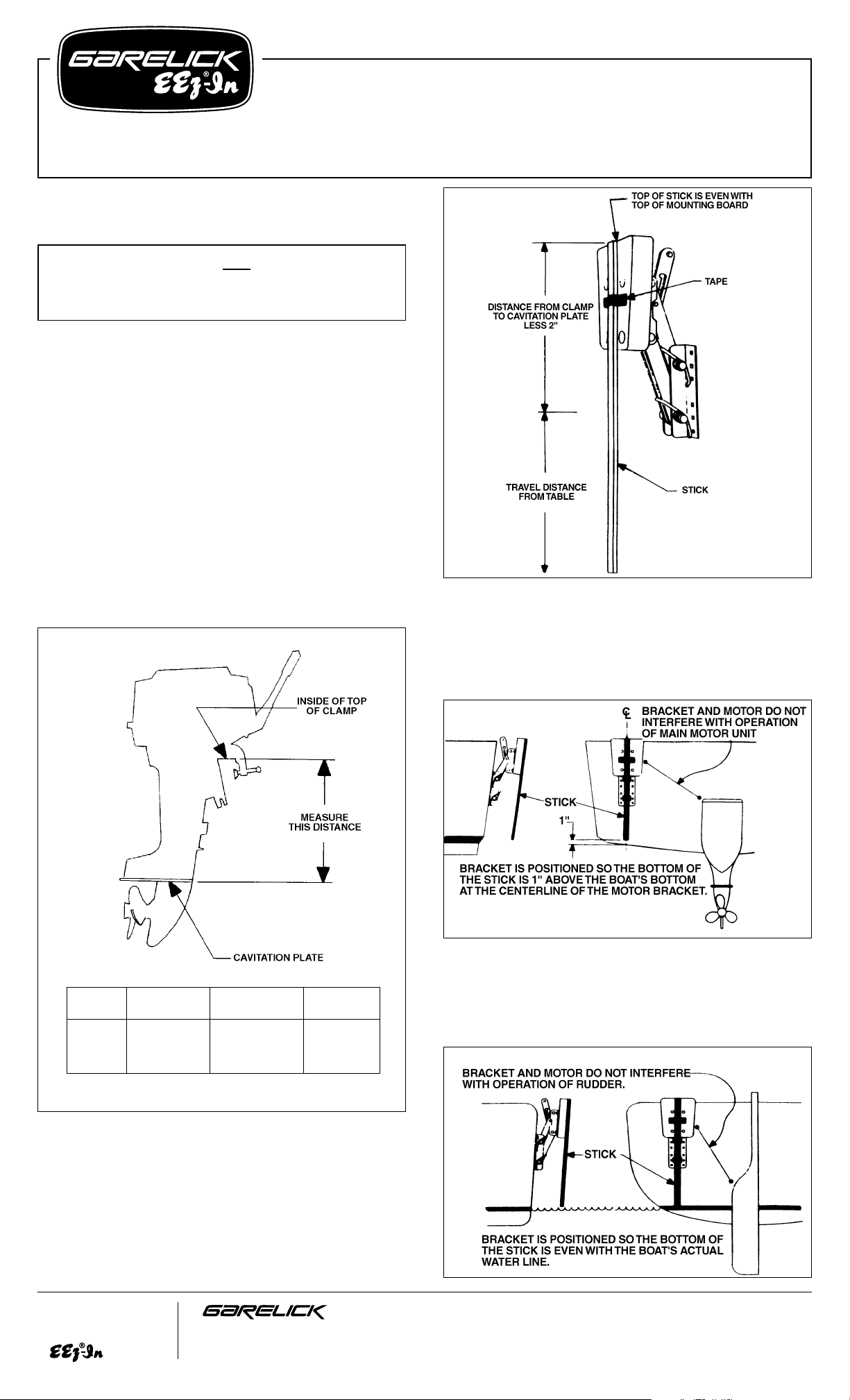
Refer to Fig. 1
Measure the distance on your outboard motor between the
cavitation plate and the upper inside edge of the mounting
clamp. Subtract 2" from this length. Then add the total travel
distance of your model outboard motor bracket from the table
below to the distance measured on your motor.
Refer to Fig. 2
Mark this total length on a stick and tape it so that the top is
flush with the top of the mounting board of the motor bracket.
Choose the most appropriate side of your transom for mounting
the bracket. Position your bracket so it will not interfere with the
turning operation of your main motor or rudder.
Refer to Fig. 3
For Powerboat Installation: Take your outboard motor bracket
with the stick taped on and place the mounting flanges on your
transom. Position the bracket so the bottom of the stick is one
inch above the boat’s bottom at the centerline of the outboard
motor bracket.
Refer to Fig. 4
For Sailboat Installation: Take your outboard motor bracket
with the stick taped on and place the mounting flanges on your
transom. Position the bracket so the bottom of the stick is even
with the boat’s actual waterline.
FIG. 3
Write for
a Complete
Catalog
Phone: 651-459-9795
PO Box 8, 644 2nd Street E-mail: mail@garelick.com
St. Paul Park, Minnesota 55071 On the Web: www.garelick.com
10/08
FIG. 1
MOTOR
WEIGHT NOT VERTICAL
MODEL H.P. RATING TO EXCEED TRAVEL
71040 TO 8 59 LBS. 8
1
⁄2"
71041 OVER 7
1
⁄2 TO 20 115 LBS. 111⁄4"
71042 OVER 7
1
⁄2 TO 12 82 LBS. 141⁄4"
71044 TO 30 135 LBS. 14
1
⁄4"
FIG. 2
FIG. 4
(over)
Transom Mounting Hardware NOT Supplied Due to Various
Transom Thicknesses.
Recommend 5/16" Stainless Steel Fasteners
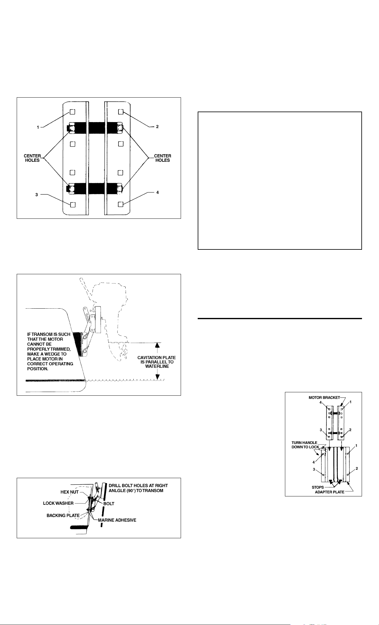
Refer to Fig. 5
After the bracket has been properly positioned, mark the four
outside hole locations using the bracket as a template on your
transom (See Fig. 5). NOTE: If it is necessary to use the center
holes on the bracket, you must reverse the mounting bolts so
their heads will be on the inside of the transom. Drill the four
marked 3/8" holes, making sure to hold the drill at right angles
to the transom when drilling.
Refer to Fig. 6
Check the angle of the transom on your boat and determine if
the motor to be used can be trimmed so the cavitation plate is
parallel to the waterline. If not make a wedge out of suitable
material to do so or, use an EEZ-IN Adjustable Angle Bracket
Model 71045.
Refer to Fig. 7
If your transom is less than 2" thick, it is recommended that a
backing plate be made and mounted on the inside of the
transom for needed rigidity. Attach your motor bracket to the
transom by coating the inside surfaces of the mounting flanges
and backing plate with a marine adhesive/sealant compound
and then squeeze a small amount into each bolt hole on both
sides of the transom. Secure the bracket to the transom as
illustrated. The bracket is now ready for motor mounting.
OPERATING INSTRUCTIONS
To move bracket bear down on motor, release locking lever by
pushing Handle towards the mounting board, allowing the
guide pin to slide in its safety groove. Bracket will snap locked
when fully extended in its “up” or “down” position. The bracket
springs counter most of the motor weight; however, a slight
push or lift is necessary to equalize this. ALWAYS LOWER
MOTOR SLOWLY. All four arm bolts on the bracket should be
tight, but not too much to prevent desirable up and down
action.
IMPORTANT RECOMMENDATIONS
A grease coating on all bolts and nuts will further increase
resistance to corrosion. Keep pivoting points lubricated.
Remove your motor from the bracket when trailering your boat.
Use a safety cable when operating your motor. Keep wood
block sealed and varnished to increase longevity.
MODEL 71053 ADAPTER PLATE MOUNTING INSTRUCTIONS
1. Check hardware packet for the following mounting
hardware:
4 - 5/16 x 3" stainless steel carriage bolts
4 - 5/16" stainless steel lockwashers
4 - 5/16" stainless steel hexnuts
Prior to installation, be certain to read instructions
completely.
2. Slide motor bracket into
adapter plate as
illustrated in Fig. 8 and
secure it in position by
turning locking handle as
indicated in Fig. 8.
3. Follow mounting instructions for Outboard Motor
Bracket on the reverse
side to correctly Position
unit. NOTE: Disregard
bracket’s hardware packet and use supplied
packet with adapter
plate. For mounting use
the adapter’s holes as a
template.
INSTALLATION INSTRUCTIONS FOR A MOUNTED MOTOR
BRACKET
If your adapter plate is to be used with a mounted outboard
motor bracket, remove your bracket from the boat and seal the
existing holes with plugs and a marine adhesive/sealant.
Position the plate on the transom so the bracket will be in the
same position as before. Follow Steps 5-7 for the Outboard
Motor Bracket to secure the plate in place.
FIG. 7
FIG. 5
FIG. 8
FIG. 6
AUXILIARY OUTBOARD MOTOR BRACKET
IMPORTANT CAUTION GUIDELINES
1. Install motor bracket only in “up” position.
2. Always remove your motor from the bracket when
trailering. Failure to do so could result in damage to
boat, motor and bracket.
3. Do not exceed the stated H.P. rating or weight.
4. Use a safety cable when operating your motor.
5. Operate motor at low speed.
6. Avoid turning motor at full throttle, refrain from sharp
turns.
7. Operate motor in lowest position possible for best
performance.
8. Always raise and tilt motor when not in use.
9. Keep pivoting bolts greased to insure smooth operation.
 Loading...