

Garelick 40028 User Manual
Mounting Instructions for
Models 40016, 40018, 40020, 40021, 40022, 40024,
40028 Seats with Folding Helmsman Hardware and
Model 75044 Side Mount Helmsman Seat Hardware
Form 12.117
MOUNTING INFORMATION
1. Check parts against parts list.
2. Read instructions completely before starting mounting.
3. NOTE: This product uses locknuts for a secure assembly.
Locknuts thread harder than conventional nuts and
require a screwdriver and wrench for attachment.
TOOLS REQUIRED
1. Screwdriver
2. Crescent wrench adjustable to 7/16"
3. Drill
MOUNTING GUIDELINES
For best utilization of your helmsman seat, it is
recommended that the seat be mounted:
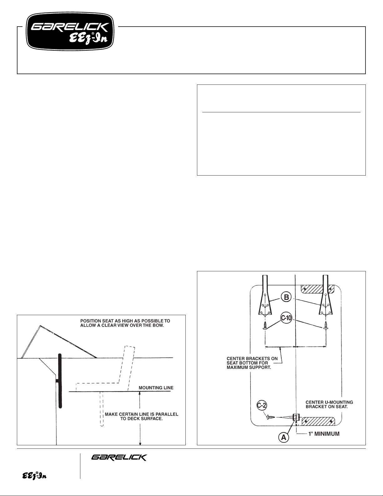
a. As high as possible to enable a clear view over the bow.
b. As close as possible to the wheel, leaving just enough
room to slide on to the seat from the side (see fig. 1).
MOUNTING INSTRUCTIONS
1. Position seat on port or starboard bulkhead of boat so it
will conform to the Mounting Guidelines given above.
Mark a line on the bulkhead where the seat bottom is
positioned (see fig. 1). Make certain that the line is:
a. parallel to the deck’s surface
b. located on a good, solid surface suitable for mounting.
NOTE: This line will be used to position U-brackets (A)
in step 7.
2. Refer to fig. 2 and position both support brackets (B) on the
bottom of the seat so that:
a. Support bracket is allowed to extend a minimum of 1"
Parts List
Ref. Factory No.
Letter Part No. Req. Description
A 50.455 4 U-mounting bracket
B 59.026 2 Support bracket
C 03.096 18 #10-
7
⁄8" screw
D 03.080 4
1
⁄4-20x11⁄2" bolt
E 03.017 4
1
⁄4-20 locknut
F 59.214 1 Stanchion leg (tapered) top
G 59.215 1 Stanchion leg bottom
H 10.001 1 1" white poly tip
FIG. 1
Write for
a Complete
Catalog
Phone: 651-459-9795
PO Box 8, 644 2nd Street E-mail: mail@garelick.com
St. Paul Park, Minnesota 55071 On the Web: www.garelick.com
5/98
from seat bottom. However, make certain that all screw
holes are located on the seat bottom.
b. Brackets are spread apart from each other on seat
bottom for maximum support and stability.
c. Brackets’ centerlines should be parallel to each other.
This will allow proper hinging action.
NOTE: It is allowable to mount support brackets over
the hinge on the seat bottom for correct positioning.
3. Mark the brackets' hole locations on the seat bottom and
drill all with a 1/8" bit.
(over)
FIG. 2 BOTTOM VIEW
4. Secure the brackets to the seat bottom by aligning the
holes and using screws (C).
5. Position U-mounting bracket (A) on seat bottom so it is
centered on the seat’s side and at least 1" from edge.
Align the U-mounting bracket so that the walls of it face
fore and aft (see fig. 2). Mark the 2 holes and drill them
with a 1/8" bit. Secure the bracket in position with 2
screws (C).
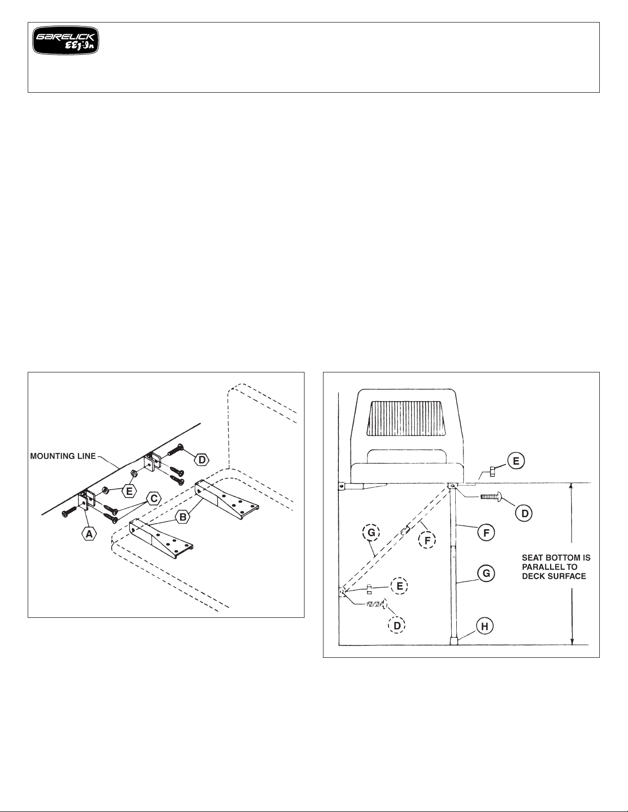
6. Attach 2 U-mounting brackets (A) to support brackets (B)
by aligning their holes and inserting bolts (D) as in fig. 3.
Secure with locknuts (E). Fingertighten only. These nuts will
have to be removed in step 8.
7. Position the attached U-mounting brackets (A) against the
line drawn in step 1. Mark the brackets’ hole locations on
the side bulkhead and drill all 4 with a 1/8" bit (see fig.
3).
8. Remove the 2 U-mounting brackets from the support
brackets and align them with the drilled holes on the side
bulkhead. Secure with 4 screws (C).
9. Attach seat to boat by aligning support brackets’ and Umounting brackets’ holes, inserting bolts (D) and securing
with locknuts (E) as in fig. 3.
10. Determine method of seat support to be used as illustrated
in fig. 4.
For angled leg mount: Attach stanchion leg (assembled)
to U-mounting brackets by using bolts (D) and locknuts (E).
Position and mark U-mounting brackets’ location on side
bulkhead at the position where seat is parallel to deck
surface. Drill the 2 bracket holes with a 1/8" bit and
secure it in position with 2 screws (C).
For straight leg mount: Attach leg (assembled) to Umounting bracket on seat bottom using bolt (D) and
locknut (E). Check to see that seat bottom is parallel to
deck surface. If not, cut off the appropriate length of
tubing with a hacksaw and slip poly tip (H) on the end of
stanchion leg. NOTE: Tip will go on more easily after
being heated in warm water.
11. If fore and aft adjustment of seat is desired, then seat may
be adapted by using Model 75005 side slide assembly.
Also, for boats used in rough water or by heavy people,
an H-type stanchion leg – Model 75014 – is available.
FIG. 3 FIG. 4
Assembly Instructions – Models 40016, 40018, 40020, 40021,
40022, 40024, 40028 Seats with Folding Helmsman Hardware
and Model 75044 Side Mount Helmsman Seat Hardware
Form 12.117
 Loading...