

Garelick 31800 User Manual
Assembly Instructions for
Model 31800 Motor Carrier
Form 12.122
ASSEMBLY INFORMATION
1. Check parts against parts list.
2. Read instructions completely before starting assembly.
TOOLS REQUIRED
1. Wrench adjustable to 7/16"
2. Screwdriver
3. Hammer
CAUTION: Woodblock and tubing will crush if over-
tightened.
MOTOR CARRIER ASSEMBLY
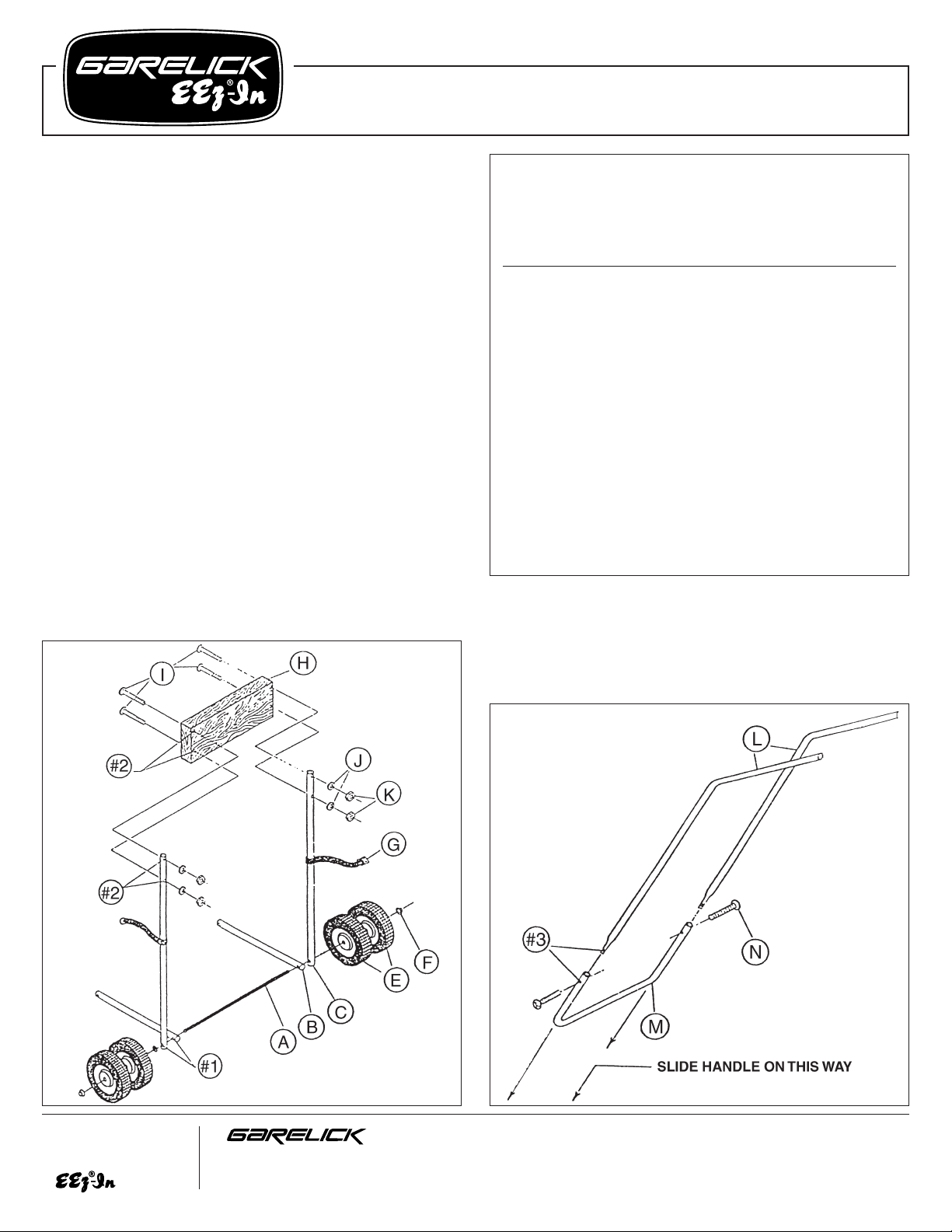
Refer to Fig. 1:
1. Slide axle (A) through large holes #1 of bottom brace tubes
(B) on each end.
2. Slide each end of axle through holes #1 of upright support
tubes (C).
3. Mount two wheels (E) on each end of axle.
4. Using hubnuts (F), secure wheels by tapping them on axle
squarely with hammer.
5. Slide loop ends of tank tiestraps (G) over upright support
tubes.
6. Attach woodblock (H) to each end of upright support tubes
by aligning holes #2, inserting four carriage bolts (I) and
securing with fasteners (J) and (K) as illustrated (finger
tighten).
Parts List
Model 31800 Motor Carrier
Ref. Factory No.
Letter Part No. Req. Description
A 51.024 1 Axle
B 51.015 2 Bottom brace, 16
1
⁄2"
C 51.027 2 Upright support tube, 33
1
⁄2"
E 49.096 4 Wheel
F 03.039 2 Pushnut
G 49.041 1 Tank tiestrap (2 parts)
H 51.029 1 Woodblock
I 03.003 4
1
⁄
4-20x3
1
⁄
2" carriage bolt
J 03.118 12
1
⁄4" lockwasher
K 03.023 12
1
⁄4-20 nut
L 51.022 2 Handle (left and right)
M 51.023 1 Bottom U
N 03.088 4
1
⁄4-20x21⁄2" bolt
O 03.089 4
1
⁄4-20x23⁄4" bolt
P 51.014 1 Handlebrace
Q 51.025 1 Tankholder U-tube
R 06.027 2 Poly handgrip
FIG. 1
FIG. 2
Write for
a Complete
Catalog
Phone: 651-459-9795
PO Box 8, 644 2nd Street E-mail: mail@garelick.com
St. Paul Park, Minnesota 55071 On the Web: www.garelick.com
3/99
Refer to Fig. 2:
1. Insert handles (L) into bottom U (M).
2. Align holes #3 in assembly so that the handles will point
AWAY fro m each other and insert bolts (N). NOTE: DO
NOT add fasteners yet.
(over)
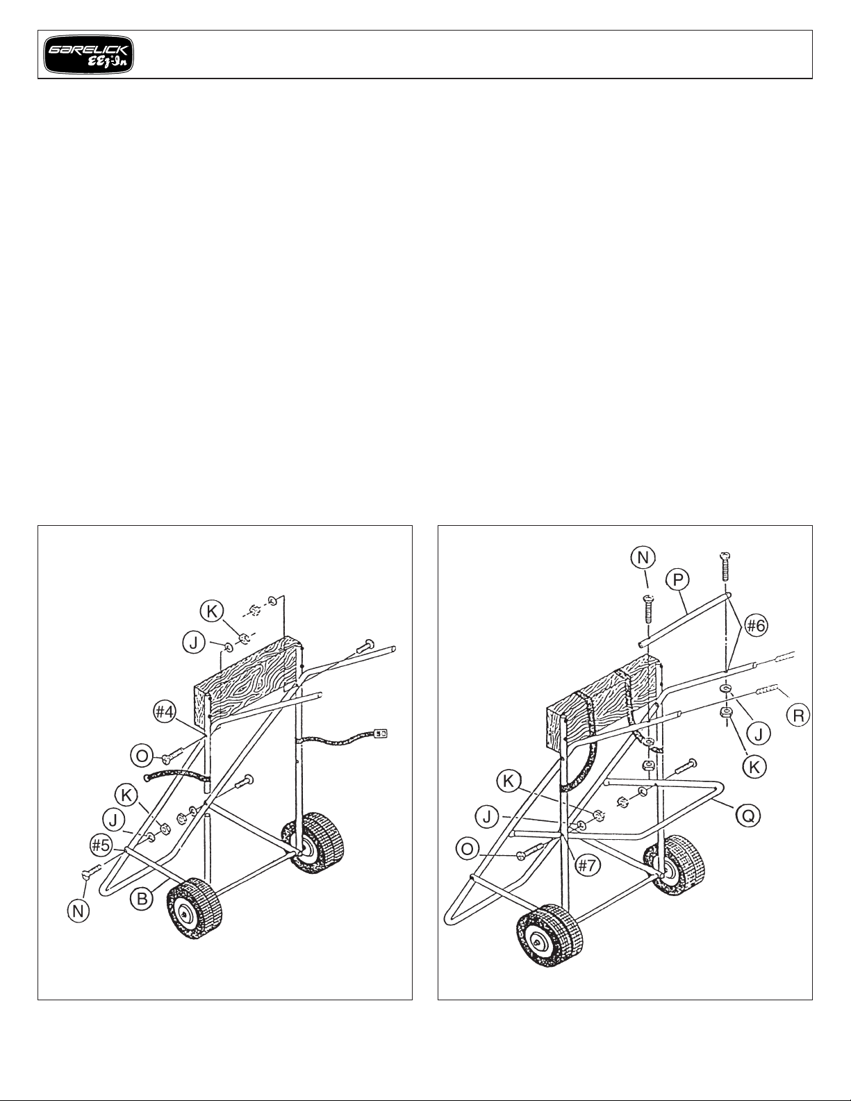
Refer to Fig. 3:
1. Slide handle assembly (Fig. 2) into upright support
assembly (Fig. 1) as shown. NOTE: Handle assembly will
rest on the INSIDES of upright support tubes.
2. Align holes #4, insert 2 bolts (O), and secure with
fasteners (J and K) as illustrated (finger tighten).
3. Align holes #5 of braces (B) and handle assembly.
NOTE: Place braces on the OUTSIDE of handle assembly.
4. Place bolts (N) from Fig. 2 through holes #5 of braces and
secure with fasteners (J and K) as illustrated (finger
tighten).
Refer to Fig. 4:
1. Attach handle brace (P) across TOPS of handles by
aligning holes #6, inserting bolts (N) and securing with
fasteners (J and K) as illustrated (finger tighten).
2. Drape tank tiestraps (H) over woodblock so loops are
above holes #7.
3. Position tankholder U-tube (Q) as illustrated. NOTE: Place
tankholder on the INSIDES of main upright tubes; U opens
out facing forward.
4. Align holes #7, insert bolts (O) and secure with fasteners
(J and K) as illustrated (finger tighten).
5. Tighten all nuts and bolts on carrier.
6. Slip poly handgrips (R) on handles. NOTE: Grips go on
more easily if they are first heated in warm water.
STORAGE AND MAINTENANCE
1. For storage, carrier can be folded by removing two bolts
at holes #4, folding up tankholder U-tube and securing in
position with tank tiestraps.
2. Periodically lubricate wheels and polish* aluminum to
ensure a long life.
*EEz-In marine polish, Model 65010, available.
FIG. 3 FIG. 4
Assembly Instructions – Model 31800 Motor Carrier
Form 12.122
 Loading...