

Page 1
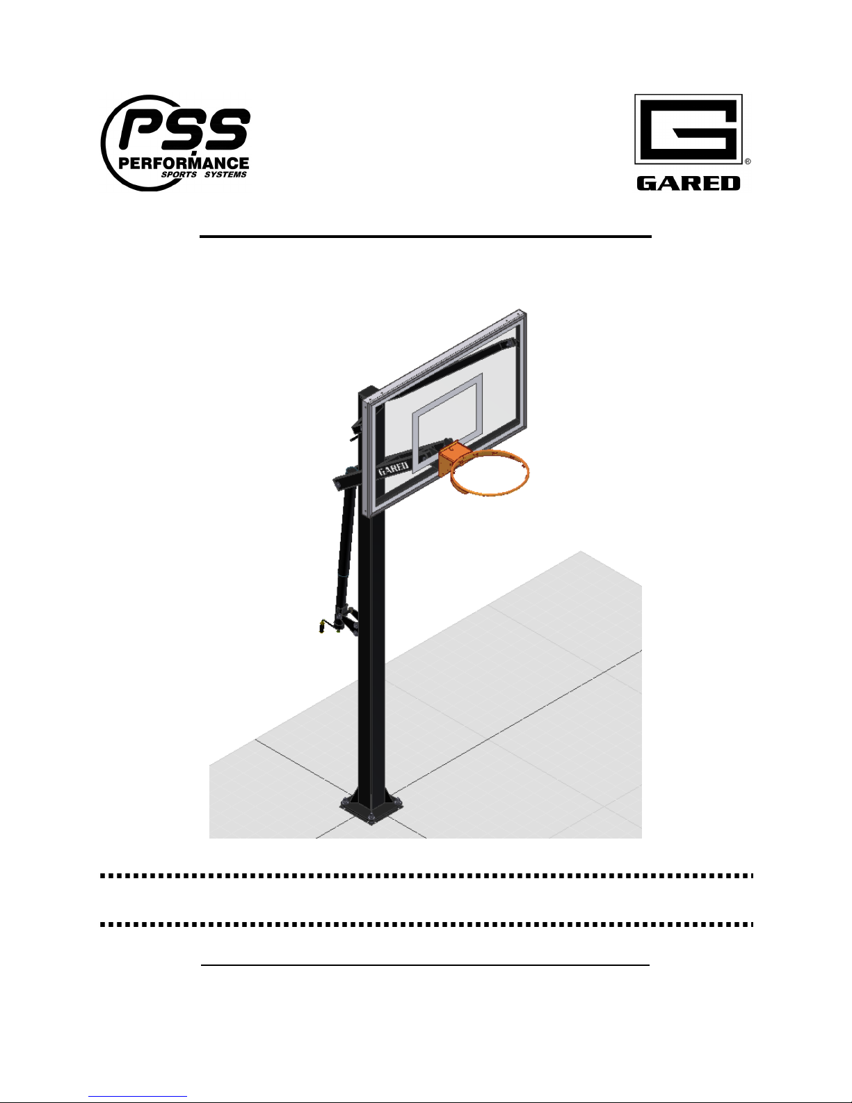
Varsity Jam Adjustable Basketball System
Models: GP7G54, GP7G60
Installation, Operation and Maintenance Instructions
Please read all instructions before attempting installation or operation of these units
SAVE THESE INSTRUCTIONS FOR FUTURE USE
P
UBLICATION NO
4 5 1 7 5 2 6 5 3
. May 28, 2014
Page 2
Varsity Jam Adjustable Basketball System
Table of Contents
Section Page No.
Introduction ..........................................................................................................................1
Safety ...................................................................................................................................2
Specifications .......................................................................................................................3
Parts Checklist ................................................................................................................. 4-5
Installation...................................................................................................................... 6-17
Optional Post and Backboard Padding ........................................................................ 18-19
INTRODUCTION
Thank you for your purchase of a Gared Sports model Varsity Jam Adjustable Backstop. To
ensure that our equipment will provide years of use to you, we are including this installation,
operation, and maintenance guide. This guide will provide information on the proper assembly
and installation methods, operating procedures, and preventative maintenance of your portable
backstop.
Please note that a Bill of Materials is being included with this guide. Please check that all of the
parts called out on the Bill of Materials are present prior to beginning assembly and setup.
Please do not substitute for factory parts. Please contact your dealer or Gared or Performance
Sports Systems customer service department and allow them to determine if substitute parts are
acceptable.
It is recommended that an individual who has been properly trained perform assembly and set up
of the backstop. No one under the age of 18 should attempt assembly or set up of the unit, unless
properly supervised.
To prevent normal wear and tear from shortening the life of the unit, preventative maintenance
inspections and repairs should be performed at least once per year. If the units are subject to
high or unusual usage, inspections should be scheduled to occur more frequently. If items are
found to be nonconforming, replacements can be ordered from Gared, Performance Sports
Systems, or one of our authorized dealers. When contacting Gared or PSS, please have
information regarding the dealer/installer who sold the unit, the name of the project, and any
applicable warranty information.
1
Page 3
Varsity Jam Adjustable Basketball System
SAFETY
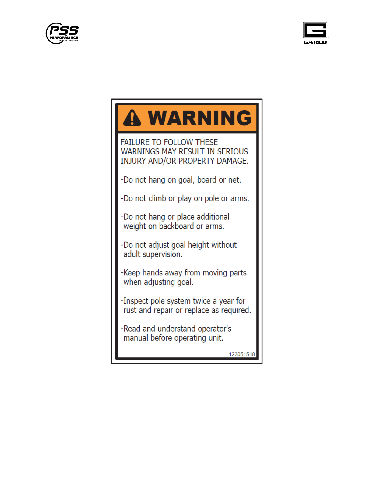
Read and understand the following warnings to prevent possible personal injury and potential
damage to the equipment during assembly, setup, and operation.
Before proceeding with assembly, read all instructions and assembly procedures. Make sure
all parts have been received and are not damaged.
2
Page 4
Varsity Jam Adjustable Basketball System
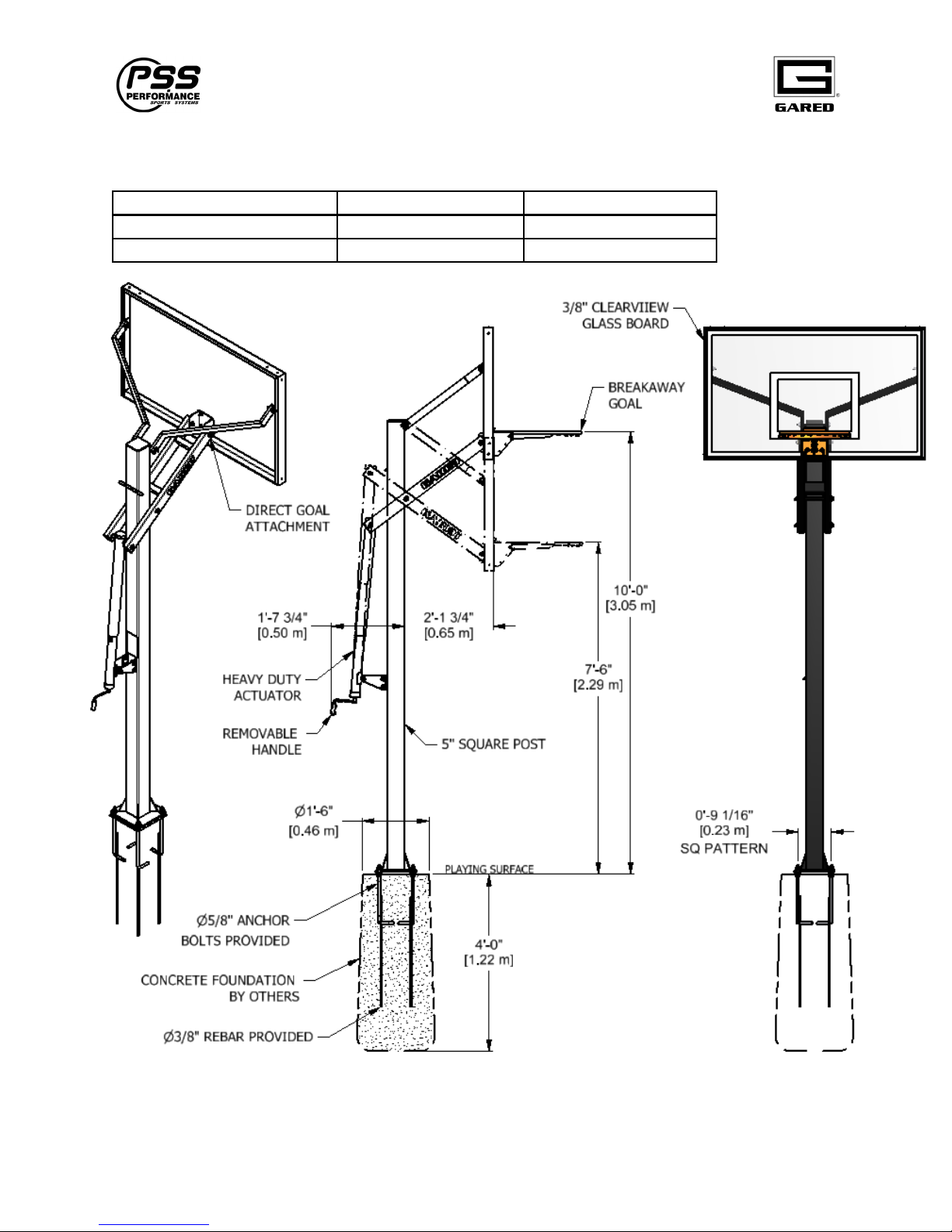
SPECIFICATIONS
MODEL GP7G54 GP7G60
Backboard size in [mm] 54" x 34" [1372 x 864] 60" x 36" [1524 x 914]
Weight lb [kg] 264 [120] 278 [126]
3
Page 5
Varsity Jam Adjustable Basketball System
GP7G54
GP7G60
453052661
453052662
ITEM
PART NUMBER
DESCRIPTION
QTY
QTY
31
453052636
ARM WELDMENT, LIFTING GP7
1
1
32
453052568
END CAP 40 X 80 X 3mm BLK
4
4
33
453052654
ARM, UPPER GP7 54"
2
33
453052639
ARM, UPPER GP7 60"
2
34
453075000
CAP, END 1 X 2" TUBE BLK
4
4
OPTIONAL PADS
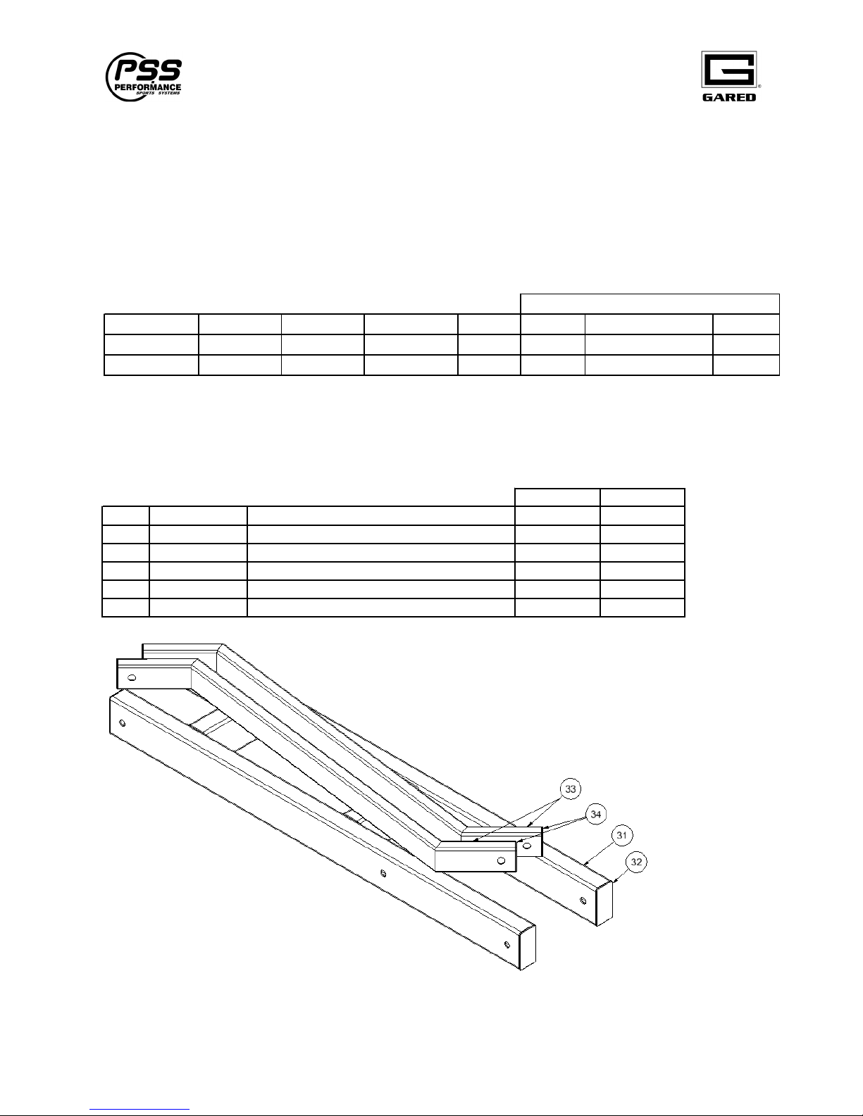
PARTS CHECKLIST
Your unit should be shipped with the following packages. Be sure that all packages and parts are
received before proceeding with installation. Please refer to your packing slip to verify the
correct board and goal has been received. You may find that some parts have been preassemble
from the factory such as Caps and Decals. Contact Gared Customer Service at
PSS Customer Service at 800-848-8034 for assistance with replacement of any parts missing or damaged.
MODEL POST PKG ARM PKG BOARD GOAL BASE POLE BOARD
GP7G54 453052650 453052651 BB5434G38 725 BP5SQ PP5SQF or PP5WR LSCE54
GP7G60 453052650 453052652 BB6036G38 725 BP5SQ PP5SQF or PP5WR LSCE60
ARM PKG, GP7
800-325-2682 or
4
Page 6
Varsity Jam Adjustable Basketball System
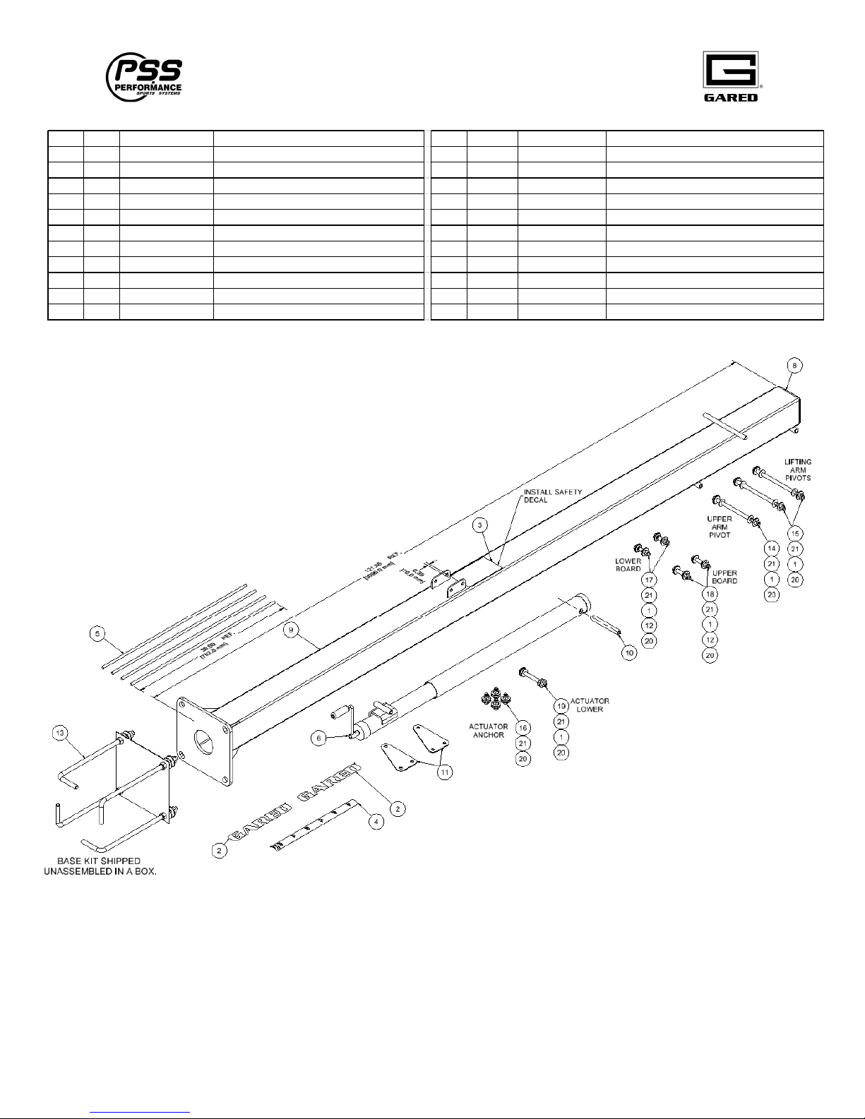
453052650 POST PKG, GP7
ITEM QTY PART NUMBER DESCRIPTION ITEM QTY PART NUMBER DESCRIPTION
1 24 111553503 WASHER,FLAT .50 X 1.25 X .06 DELRIN BLK 12 4 453052647 FLANGE BUSHING, 500x.625x.25 NON-MET
2 2 121974131 DECAL, GARED 1.7" WHITE 13 1 453052649 BASE HARDWARE KIT W/ TEMPLATE GP7
3 1 123051518 DECAL, WARNING GP SERIES 14 1 502-8-13-144 HEX BOLT, 1/2-13 UNC X 9
4 1 123051528 DECAL, HEIGHT ADJUST GP7 15 2 502-8-13-160 HEX BOLT, 1/2-13 UNC X 10
5 4 451652627 REBAR, 3/8 X 30"' LONG 16 4 502-8-13-20 HEX BOLT, 1/2-13 UNC X 1.25
6 1 451652644 ACUATOR ASSY, GP7 TOP WIND 17 2 502-8-13-40 HEX BOLT, 1/2-13 UNC X 2.5
7 1 451752653 MANUAL, INSTAL-OPER GP7 18 2 502-8-13-48 HEX BOLT, 1/2-13 UNC X 3
8 1 453052569 CAP, END 120mm SQUARE POSTS 19 1 502-8-13-80 HEX BOLT, 1/2-13 UNC X 5
9 1 453052630 POST WELDMENT, GP7 20 12 545-8-13 HEX NUT, NYLON LOCK 1/2-13
10 1 453052634 TUBE, ARM PIVOT GP7 (5.55") 21 24 561-8 FLAT WASHER 1/2
11 2 453052642 PLATE, ACTUATOR ANCHOR
5
Page 7

Varsity Jam Adjustable Basketball System
INSTALLATION
Tools and Materials Required for Assembly:
1. (2) 12” Adjustable Wrenches.
2. Socket Set with 9/16”, ¾” sockets
3. 9/16” & ¾” End Wrench
4. Tape Measure
5. Hammer or Rubber Mallet
6. Shovel
7. Post Hole Digger.
8. Carpenter’s Level
9. (2) Heavy Duty Step Ladders
10. (2) Sawhorses
(For Optional Board Padding)
11. Phillips Head Screwdriver
12. Electric Drill,
13. 11/64” Drill Bit
Materials Required for Assembly:
1. Concrete –1/2 yard or 15-16 bags of pre-mix (80 lb. bags)
2. (1) 2” x 4” x 8ft for forms.
6
Page 8
Varsity Jam Adjustable Basketball System
INSTALLATION INSTRUCTIONS
INSTALL FOUNDATION
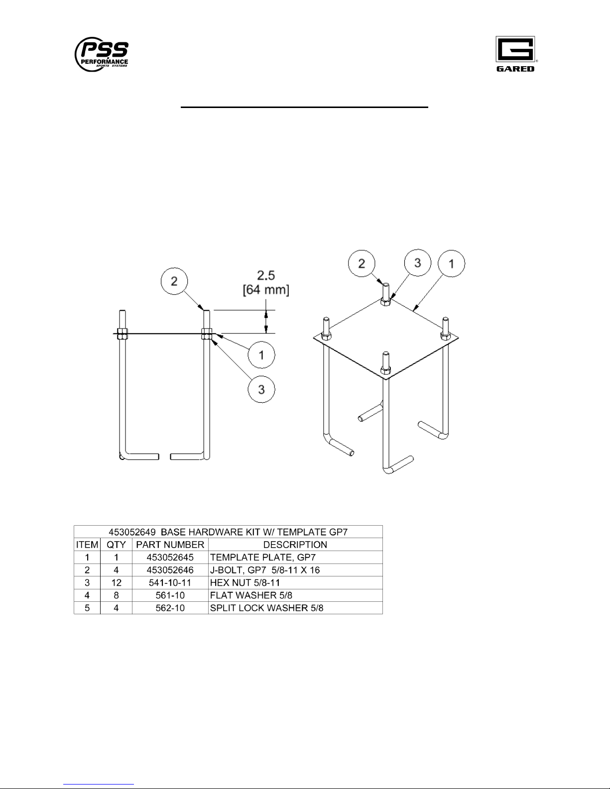
1. Assemble template plate and ‘J’ Bolts as shown in fig #1.
a. Find Template Plate and hardware in boxed inside the Post Package.
b. Install 5/8-11 Nut, item 3, onto each J-Bolt, item 2.
c. Insert J-bolt into Template Plate, item #1, and secure with 5/8-11 Nut, item #3.
d. Adjust until top of J-bolt is approximately 2.5” above Template Plate.
e. Arrange the J-bolts in the pattern indicated and tighten Nuts.
Fig #1
7
Page 9
Varsity Jam Adjustable Basketball System
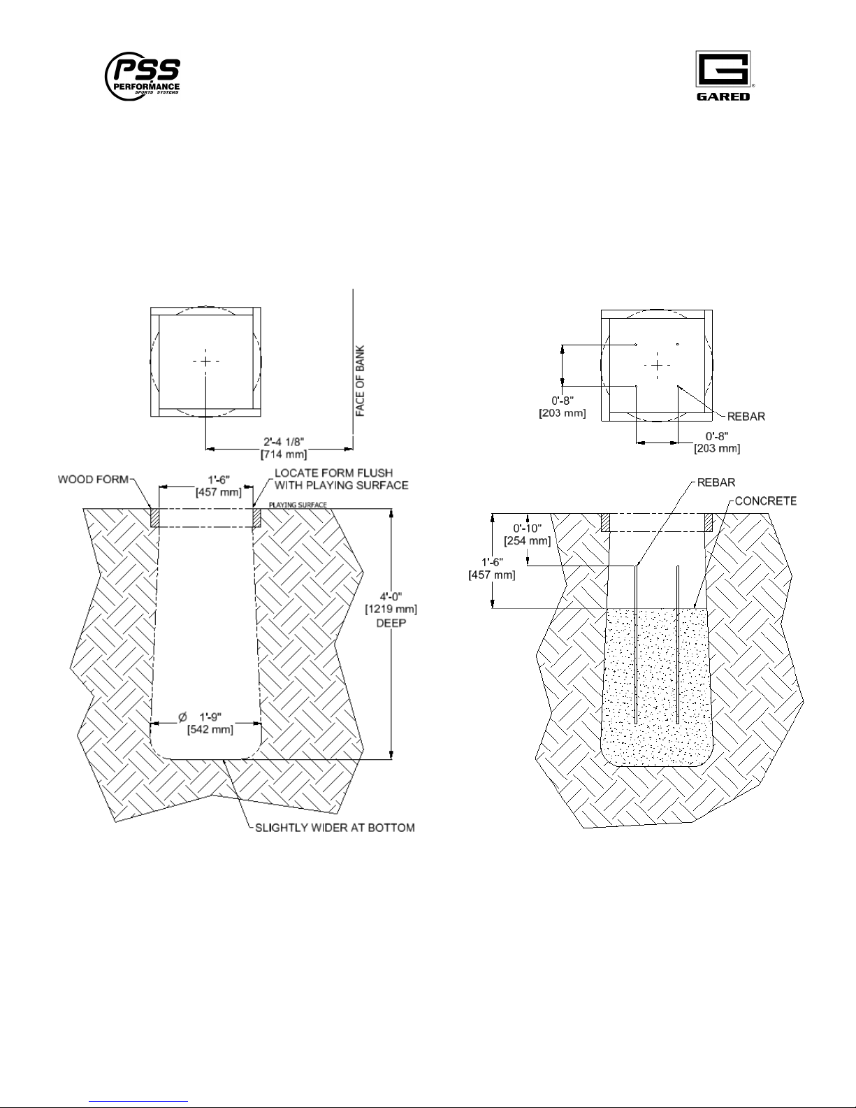
2. Use the illustration fig #2 below to dig and prepare the hole for casting and anchoring
the template plate. The center of hole should measure as shown for the correct Face of
Bank location.
a. Fill the hole with concrete to within 18” of surface as shown in fig #3.
b. Insert (4) 30” pieces of rebar into concrete on an 8” square pattern as shown in fig
#3. Rebar should be positioned vertically 10” below the top of forms.
c. Finish filling the hole with concrete.
Fig #2 Fig #3
8
Page 10
Varsity Jam Adjustable Basketball System
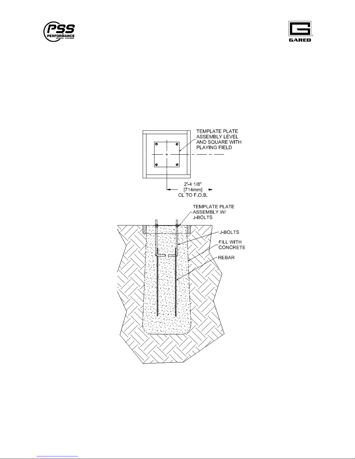
3. Set the Template Plate Assembly with J-bolts attached into the wet concrete.
a. Push template down flush with the top of the forms.
b. Agitate the Template Plate Assembly repeatedly to eliminate air bubbles in the
concrete. Template should be resting on the level and finished concrete.
c. Level and square the template to obtain the desired Face of Bank (F.O.B.) as
shown in fig #4.
d. Clean off any concrete from the template plate and exposed J-bolt threads.
e. Allow concrete to cure a minimum of 72 hours before installing the rest of
the basketball system.
Fig #4
9
Page 11
Varsity Jam Adjustable Basketball System
INSTALL POST
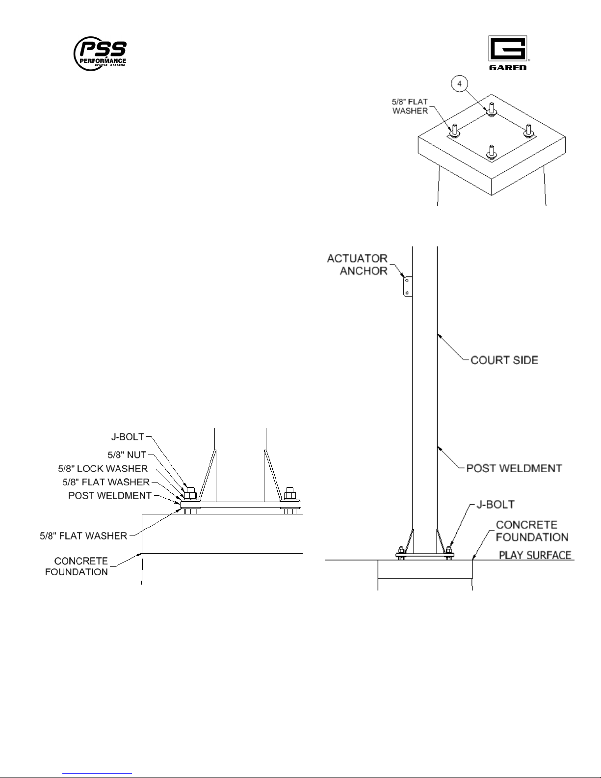
1. Concrete should be cured for 72 hours before removing
forms and continuing installation.
2. Place (4) 5/8” Flat washer on top of the (4) 5/8-11 Nuts
as shown in Fig #5.
3. Raise and place the main post over the J-
bolts as shown in fig #6. The post is heavy,
so use at least two people for this operation.
Be sure that the post is installed with the
Actuator Anchor on the side away from the
court.
4. Secure post with (4) 5/8” Flat Washer, 5/8”
Lock Washer, and 5/8-11 Hex Nut as shown
in fig 7.
Fig #5
Fig #7 Fig #6
5. If the post is not exactly vertical, adjust the bottom nuts on the base to level. If the post is
not exactly square to the court, rotate it.
6. When the post is vertical and square to the court, tighten all nuts securely.
10
Page 12
Varsity Jam Adjustable Basketball System
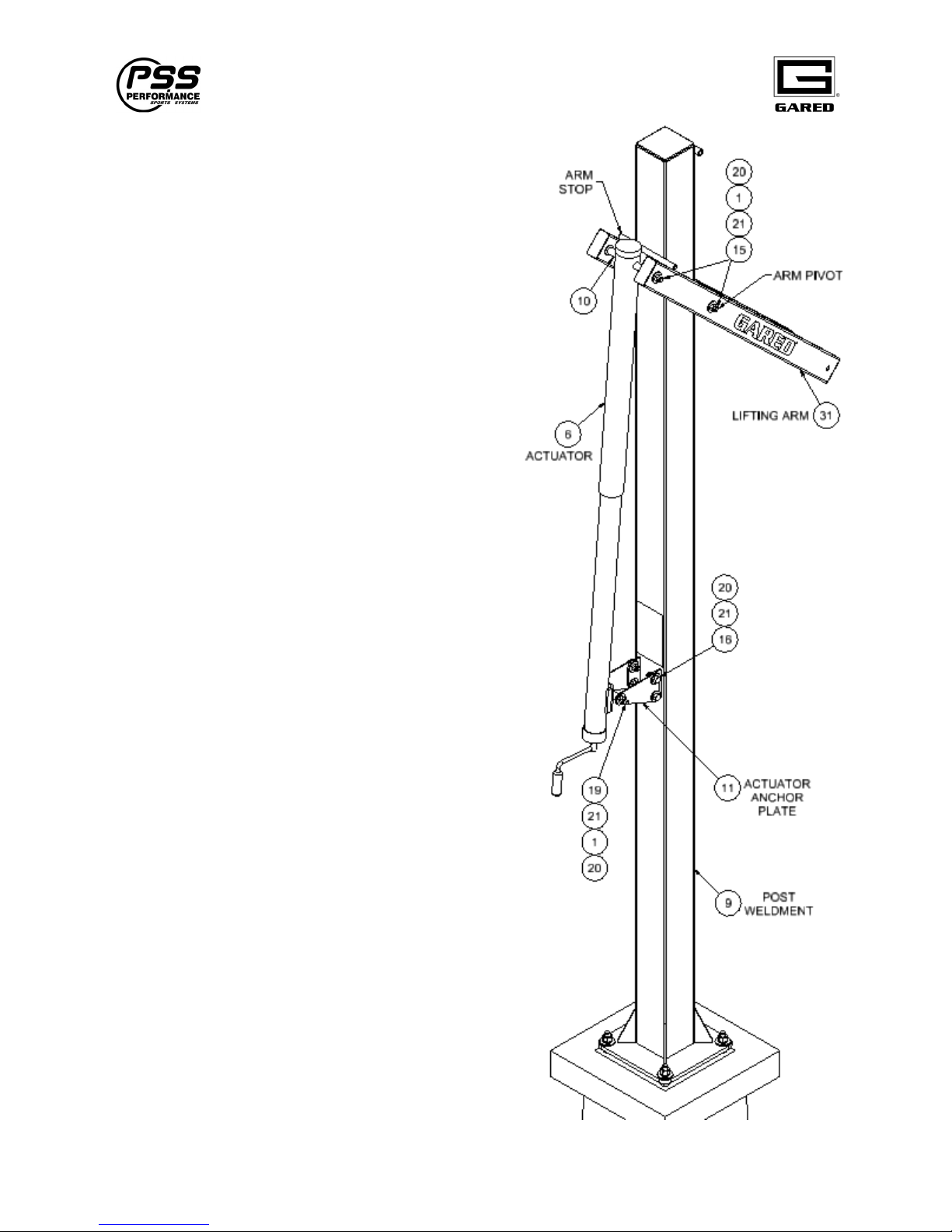
INSTALL LIFTING ARM AND ACTUATOR
Follow the steps below to assemble the unit in the
proper sequence. See the instructions on the
following pages for more detailed information.
Ballooned parts reference the packing list item
numbers
11
Page 13
Varsity Jam Adjustable Basketball System
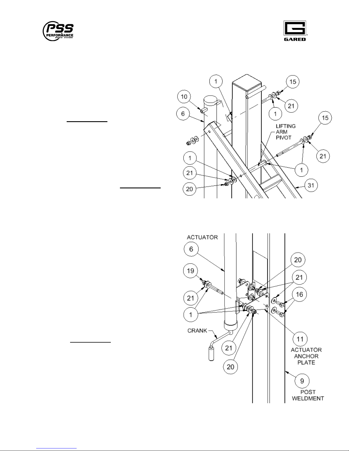
Install Lifting Arm and Actuator
1. Attach the Lifting Arm, #31, to the Post
Weldment using ½” x 10” Bolt, #15, and
hardware indicated. Allow Lifting Arm to
rest on Arm Stop when bolt is inserted.
Tighten Lock Nut to remove clearance
only. Do not torque.
2. Attached upper end of Actuator, #6, to
Lifting Arm using Tube, #10 and ½” x 10”
Bolt, #15, with hardware indicated. Tube
should pass through both the hole in the
plastic rain sleeve and the hole in the
Actuator. Tighten Lock Nut, #20, to
remove clearance only. Do not torque.
3. Attach the Actuator Anchor Plates, #11, to
the Post Weldment using ½ x 1 ¼” Bolts,
#16, and hardware shown. Tighten bolts.
4. Attach the Crank Handle and crank the
Actuator clockwise to lengthen it until the
crank end can be attached to the Anchor
Plate, #11 on the Post Weldment using a ½” x
5” Bolt, #19, and hardware as indicated.
Tighten Lock Nut, #20, to remove clearance
only. Do not torque.
5.
12
Page 14
Varsity Jam Adjustable Basketball System
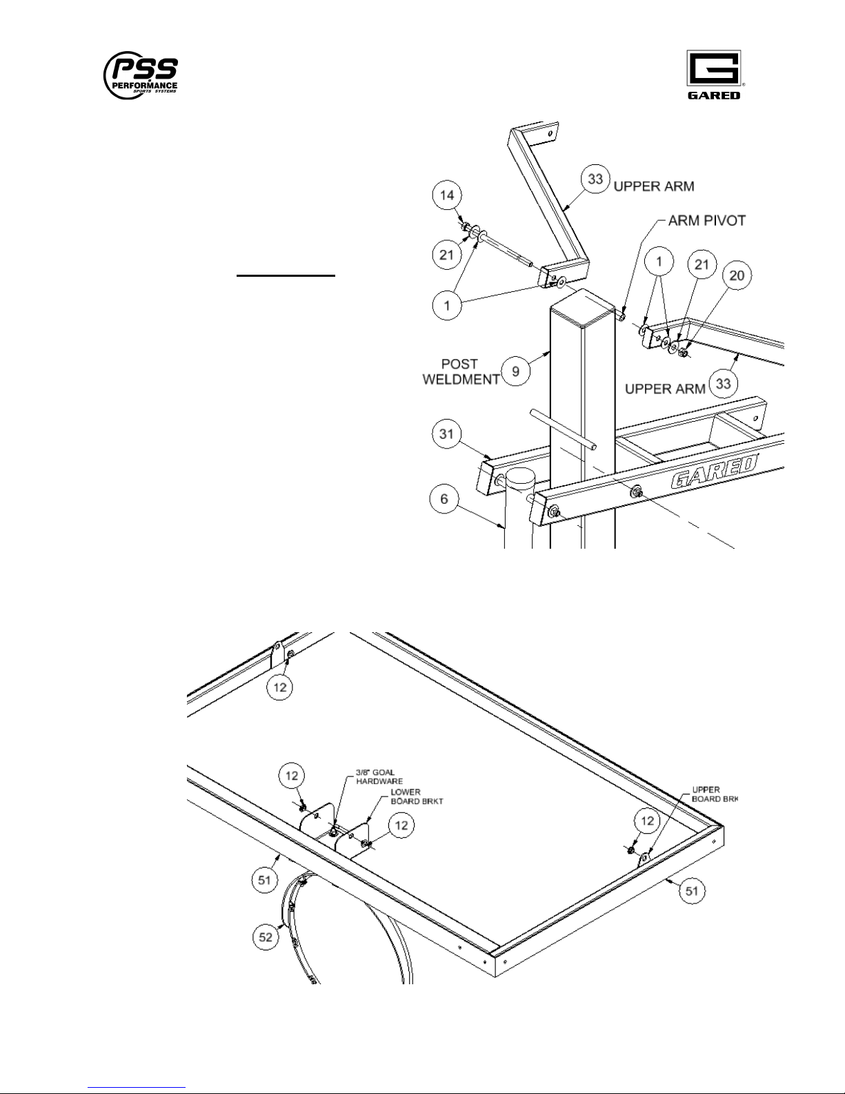
Install Upper Arms
6.
Attach Upper Arms, #33, to the Upper Arm
Pivot in the Post Weldment, #9, using ½” x
9” Bolt, #14, and hardware indicated. Allow
arms to swing vertically down at this time.
Tighten Lock Nut, #20, to remove
clearance only. Do not torque.
Prepare Board for Installation
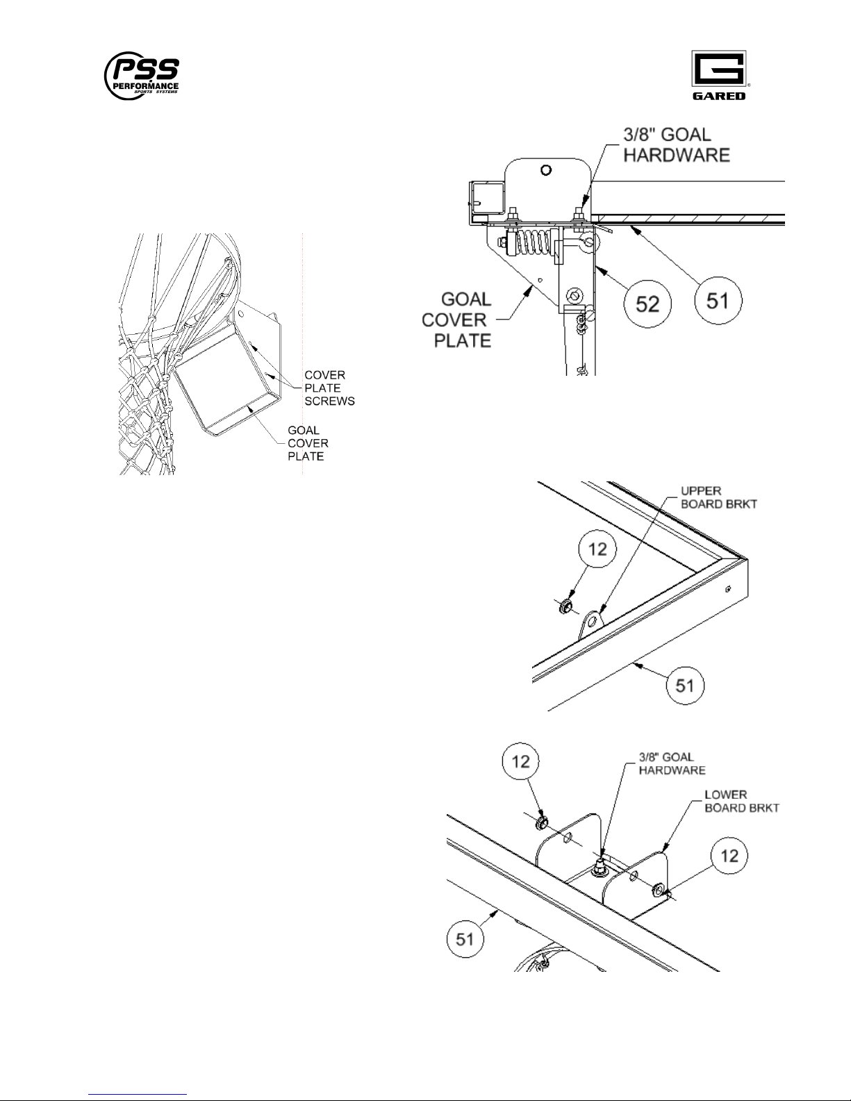
1. Support Backboard on (2) sawhorses with the goal side down. Use cardboard packing
material under board face to prevent scratching glass and frame
13
Page 15
Varsity Jam Adjustable Basketball System
2. Remove Goal Cover to gain access to
Goal mounting hardware. Attach Goal,
#52 to front side of Board, #51, using
3/8” hardware and instructions provided
with goal.
3. Install ½” Flanged Bushing, #12 into the two Upper Board
Brackets located on the outer edges of the board. Insert
Bushing from the inside as shown. A light tap from a
rubber mallet may be required to seat Bushing.
4. Install ½” Flanged Bushing, #12, into the two
Lower Board Brackets located on the back
side of the goal plate. Insert Bushing from
the outside as shown. A light tap from a
rubber mallet may be required to seat
Bushing.
14
Page 16
Varsity Jam Adjustable Basketball System
Install Board
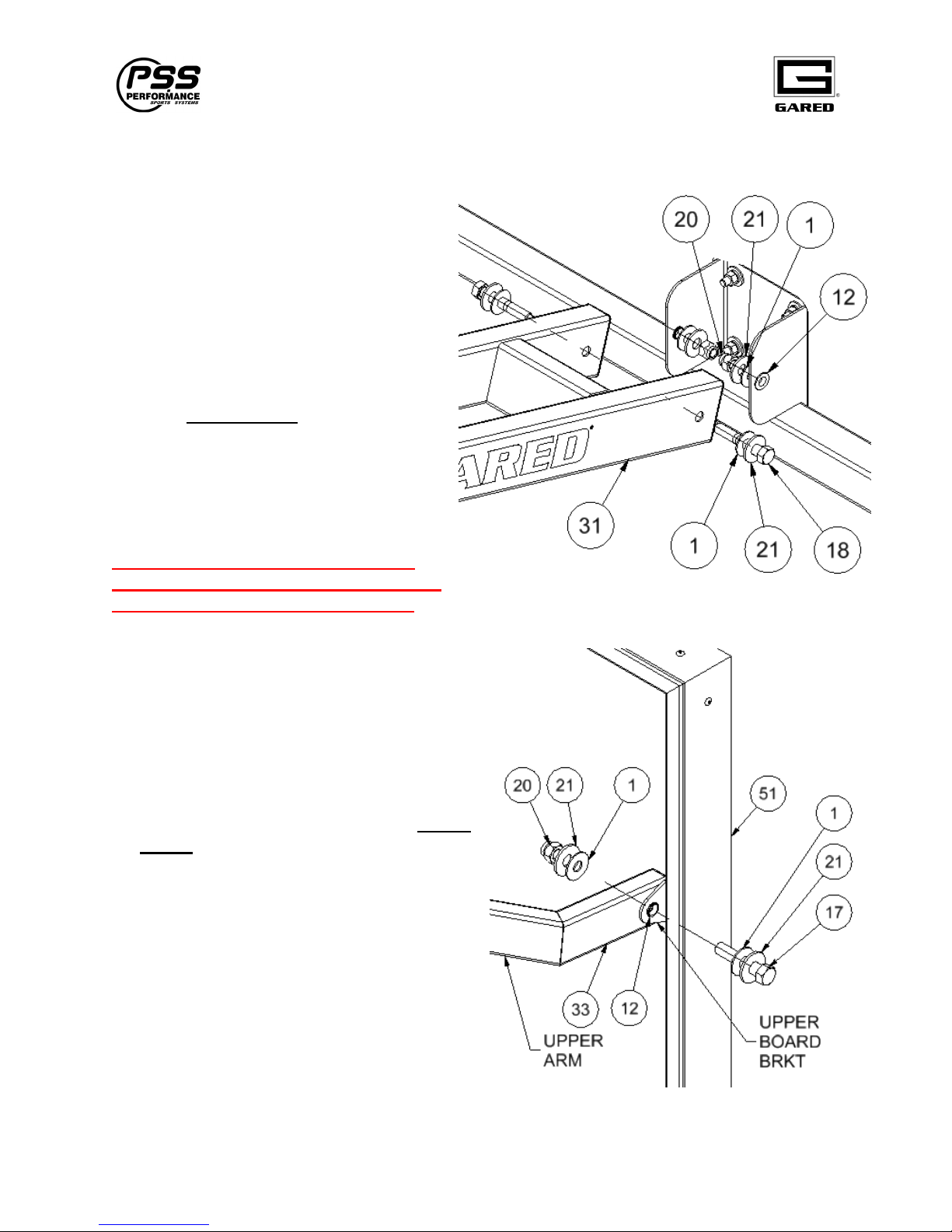
1. Be sure Bushing, #12, has been
installed. Attach the Backboard and
Goal onto the Lifting Arm, #31, with (2)
1/2 x 3” Bolts, #18, and hardware as
indicated. It is easiest to mount the
board with the Lifting Arm in the full
down position, resting on the Arm Stop.
The Lifting Arm, #31 will go to the
outside of the Lower Board Brackets.
Tighten Lock Nut to remove clearance
only. Do not torque.
*Helpful hint; Working out of the bed of a
truck may be easier than using ladders. The
backboard is very heavy.
The Board and Goal can weigh nearly
125 lbs. Make sure that you have enough
help to complete this operation safely!
2. Be sure Bushing, #12, has been installed.
While holding the Board in a vertical
position, swing the Upper Arms, #33, up to
meet the Upper Board Brackets and attach
using 1/2” x 2 ½” Bolts, #17, and hardware
as indicated. Arm should be located to the
inside of the Upper Board Bracket. Tighten
Lock Nut to remove clearance only. Do not
torque.
15
Page 17
Varsity Jam Adjustable Basketball System
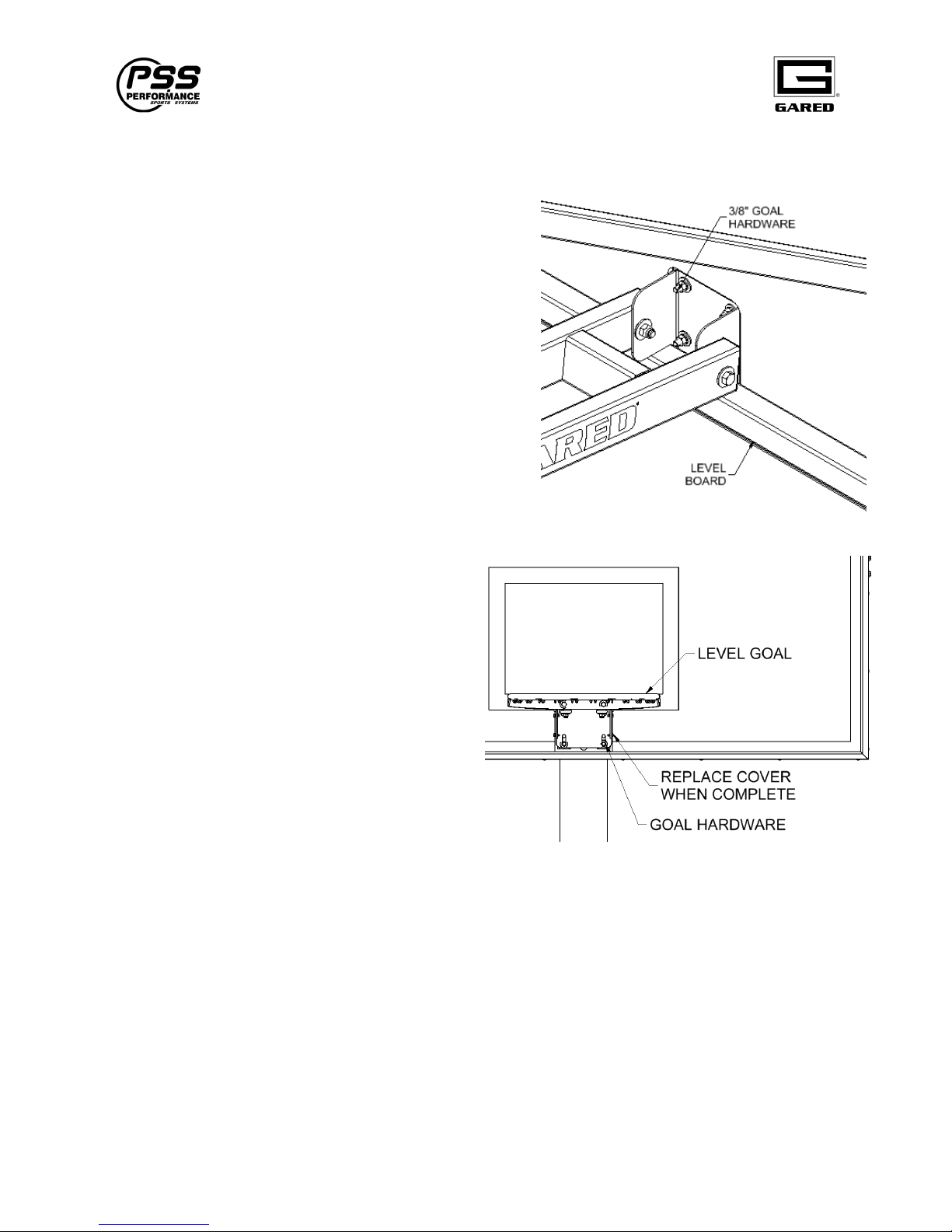
Level Goal
1. Check the level of the bottom of the Board and the
top of the Goal. If adjustments need to be made,
loosen 3/8” goal hardware. Level Board and Goal
and retighten.
2. Be sure that all Board and Goal hardware is
tight. Install Goal Cover plate.
16
Page 18
Varsity Jam Adjustable Basketball System
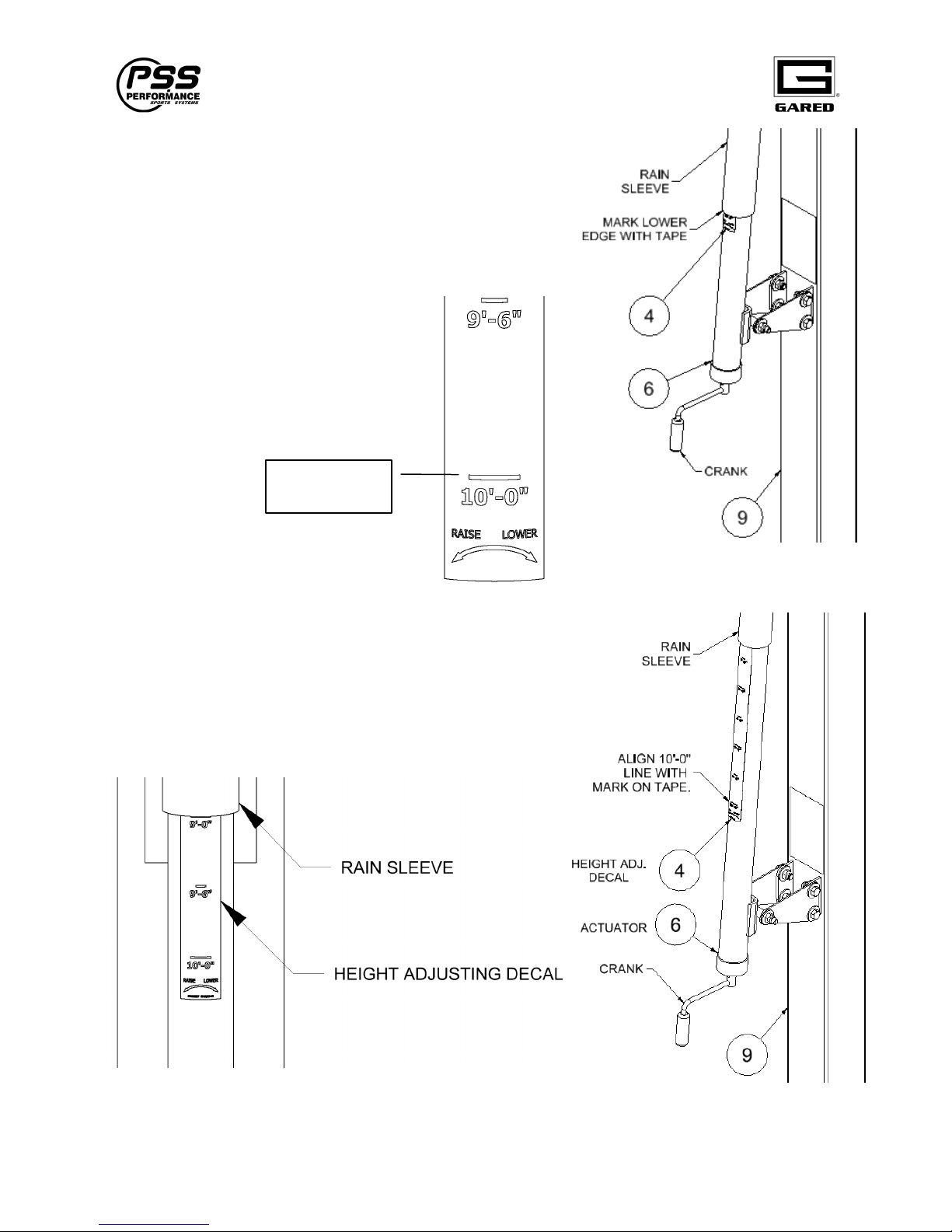
Install Height Adjusting Decal
1. Crank Goal to the 10’-0” position. Crank counter-
clockwise to raise goal. Measure from the playing
surface to the top of the goal ring. Using a piece of tape,
mark the location of the lower edge of the rain shield.
2. Crank the Goal to the minimum
height so that the Lifting Arm rests
on the stop. Crank clockwise to
lower.
Align with 10’
mark on tape.
3. Apply Height Adjusting Decal, #4, so that the 10’-0”
line aligns with mark from step #1.
4. Adjust Goal to the desired playing height by cranking
up or down until the desired height mark aligns with
the lower edged of the Rain Sleeve.
17
Page 19
Varsity Jam Adjustable Basketball System
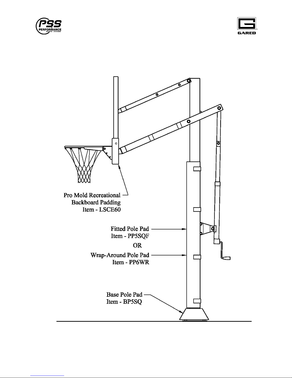
Installing Optional Padding
Note: The padding options shown below are purchased separately.
18
Page 20
Varsity Jam Adjustable Basketball System
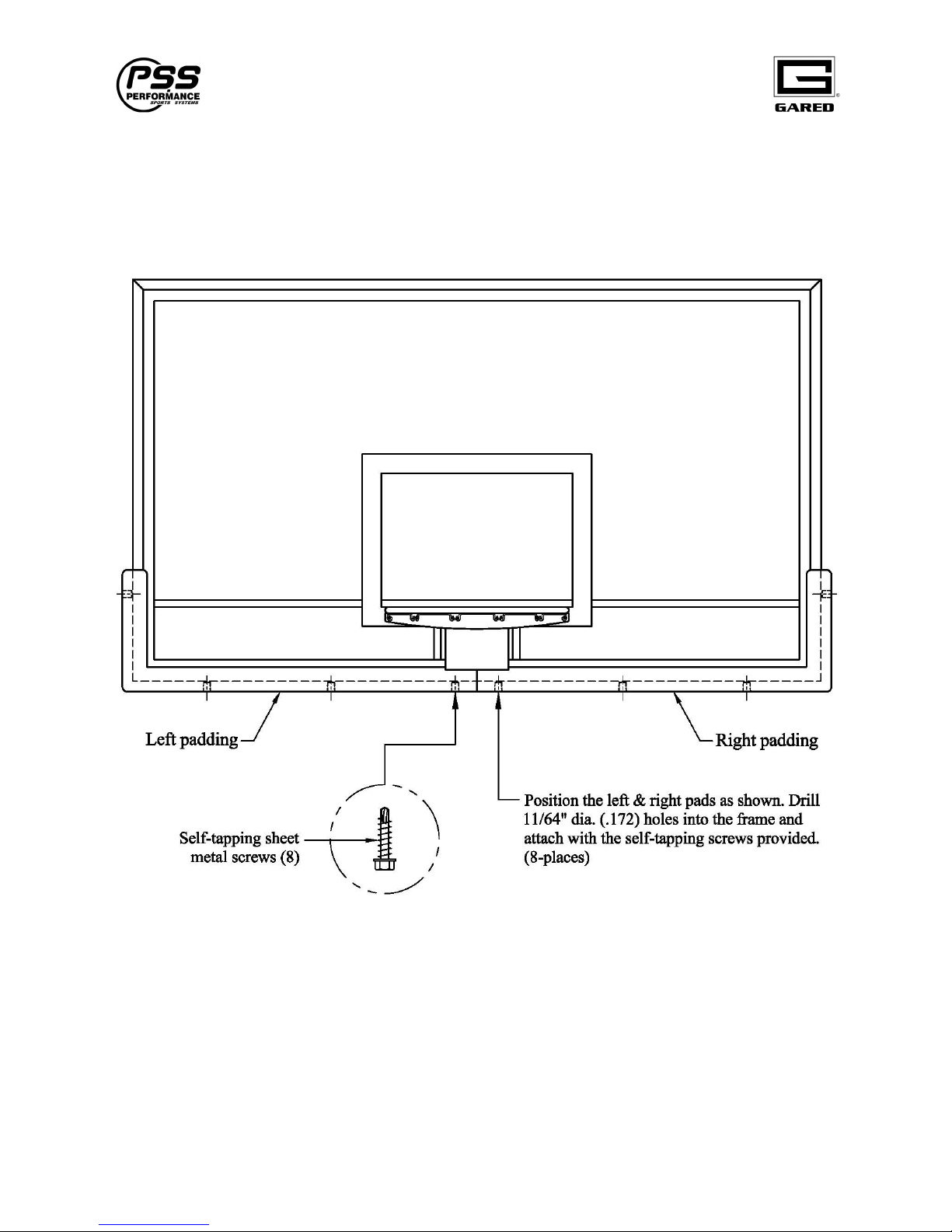
The following illustration shows how to attach the optional LSCE54 or LSCE60 Pro Mold
Recreational Backboard Padding (if purchased). The padding may be attached before or after the
backboard has been mounted in.
19
Page 21

Varsity Jam Adjustable Basketball System
20
Page 22
Gared Holdings, LLC
Performance Sports Systems Gared Sports
9200 E. 146th Street 707 North 2nd Street
Noblesville, IN 46060 St. Louis, MO 63102
800-848-8034 800-325-2682
www.perfsports.com www.garedsports.com
 Loading...