

Page 1
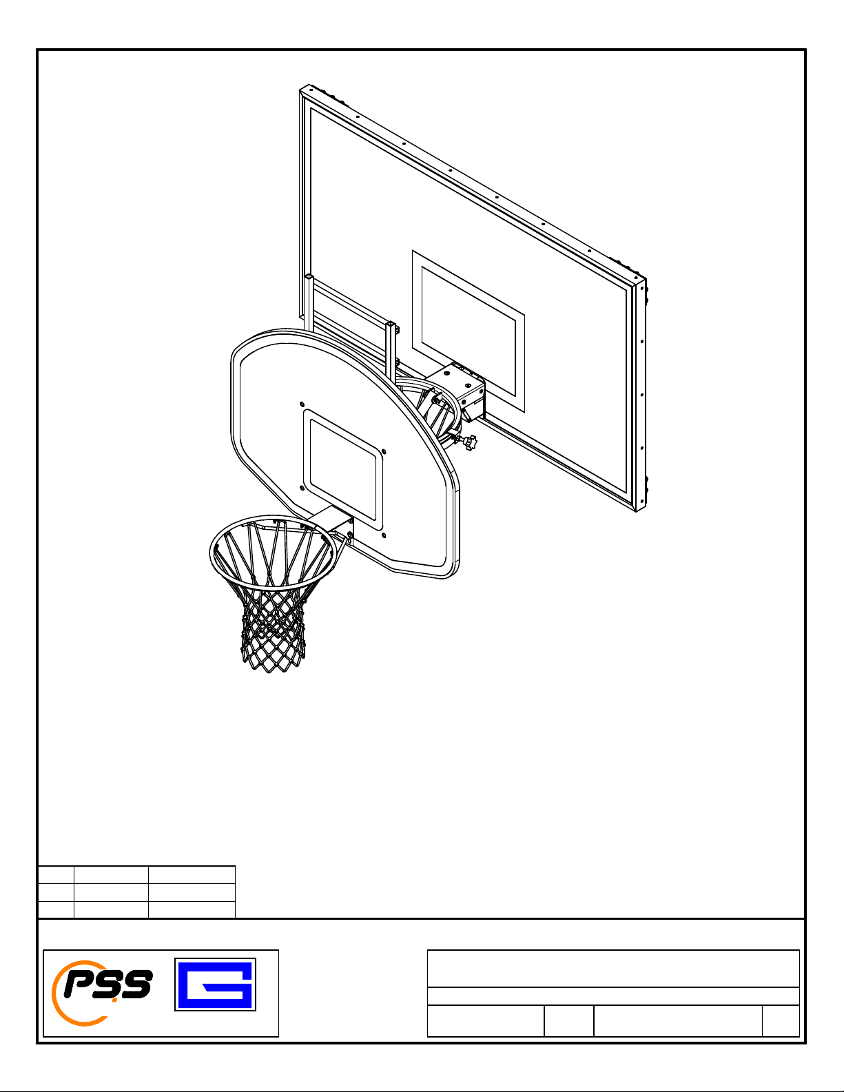
ADJUSTABLE JUNIOR JAMMER
INSTALLATION INSTRUCTIONS
B JJC 03/26/19
A MJP 3/14/2019
REV BY DATE
Installation and Assembly Instructions
PERFORMANCE
SPORTS SYSTEMS
GARED
Gared Holdings, LLC
9200 E. 146th St.
TM
Noblesville, IN 46060
ADJUSTABLE JUNIOR JAMMER
FILE LOC.
Q:\Inventor Files\_xxxx-xx-xx\JJ5 MODEL
DATE
3/14/2019
SHT. NO. PART NO. REV
1
OF 6
JJ5A
B
Page 2
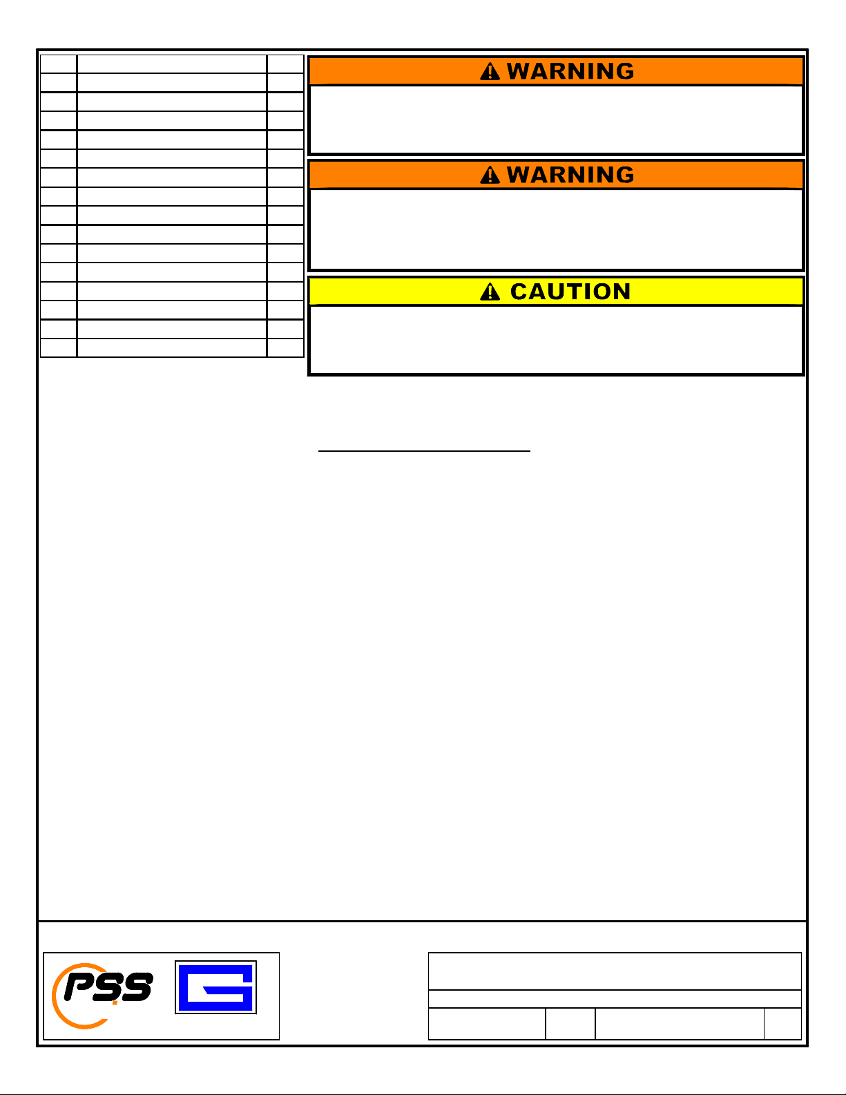
NO. DESCRIPTION QTY.
ASSEMBLY INSTRUCTIONS
mm (9),
BACKBOARD FRAME ASSEMBLY (14). NOTE THAT FOR THE GOAL HEIGHTS FROM 7 ½ FT
1 BACKBOARD (1320B) 1
2 GOAL (28WO) 1
3 NET (PACKED WITH GOAL) 1
4 UPPER FRA M E ASSEMBLY 1
5 LOWER FRAM E CONNECT OR 1
6 UPPER FRA M E CONNECT OR 1
7 HAND KNOB M 12 X 50mm 2
8 HAND KNOB M 12 X 60mm 2
9 HEX HEAD M 8 X 70mm 4
10 HEX HEAD M 8 X 60mm 2
11 M8 FLAT WASHER 6
12 M8 FLANGE NUT 10
13 CARRIAGE BOLT M 8 X 60mm 4
14 BACKBOARD FRA M E ASSEMBLY 1
15 JAM NUT M 12 2
Do not install or use this unit when subject to the possibility of users hanging on the rim
or Slam Dunking.
Hanging on the rim or Slam Dunking can cause the unit to fall resulting in damage to
equipment and/or serious injury to personnel.
Hand knobs must safely secure the upper frame to the existing goal. The point of the
hand knob MUST contact the goal beneath the welded support flange or goal rim in
order to properly lock in place.
Failure to secure hand knobs in position could allow the unit to fall causing damage to
equipment and/or serious injury to personnel.
Do not install or use this unit on portable backstops that are NOT securely anchored to
the floor.
Portable backstops that are not anchored to the floor can tip during play causing
damage or injury to personnel.
This unit should be assembled and installed by adults. Once installed properly onto a permanent existing basketball
goal, play should be supervised by an adult. Supervision of play is required to prevent players from hanging on the
rim or slam dunking on the unit. Hanging on the rim or slam dunking can damage the unit and in extreme cases
cause injury to personnel.
One unit includes one backboard, one goal (with net), one upper framework, one lower framework, one
hardware kit in three boxes. Check instructions and packing instructions to be certain no parts are
missing.
1) Using carriage bolts M8x60mm (13) and M8 flange nuts (12), assemble backboard frame assembly
(14) to backboard (1).
2) Assemble net (3) to goal (2), then assemble goal (2) to backboard (1) using hex head M8x70mm (9)
on top two holes and hex head M8x60MM (10) on bottom two holes of goal with M8 flat washers
(11) and M8 flange nuts (12) as shown in detail.
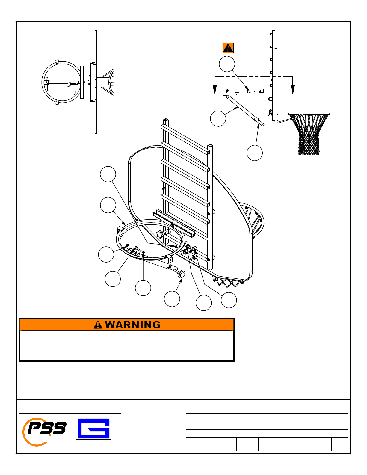
3) Assemble lower frame connector (6) to backboard frame assembly (14) using hex head M8x70mm
(9). Assemble upper frame connector (5) to upper frame assembly (4) using hex head M8x70
M8 flat washer (11), and M8 flange nut (12) as shown on page 5. Install hand knob (7) on upper
frame connector (6) and upper frame assembly (4).
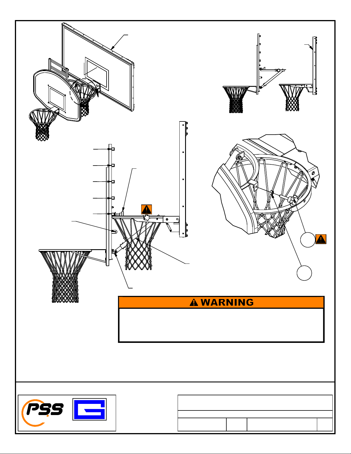
4) With the help of an assistant, place assembled unit onto permanent goal hoop. Ensure lower frame
connector (5) is engaged in upper frame connector (6) as shown in illustration, insert and tighten
hand knob M12 x 50mm (7) and secure with jam nut M12 (15) on both sides.
IMPORTANT NOTE: KEEP UPPER AND LOWER FRAME CONNECTORS (5) & (6) JOINED TO
THE UPPER FRAME ASSEMBLY (4) AND CONNECT THIS ADJUSTABLE BRACE TO THE
TO 9 FT THE LOWER ANCHOR POSITION ON THE BACKBOARD FRAME IS USED, FOR
GOAL HEIGHT OF 7 FT (LOWEST HEIGHT) THE UPPER ANCHOR POSITION ON THE
BACKBOARD FRAME IS USED. USE THE ADJUSTABLE BRACE TO PLUMB THE
BACKBOARD AND LEVEL THE GOAL.
Installation and Assembly Instructions
Gared Holdings, LLC
9200 E. 146th St.
PERFORMANCE
SPORTS SYSTEMS
TM
Noblesville, IN 46060
GARED
FILE LOC.
DATE
3/14/2019
ADJUSTABLE JUNIOR JAMMER
Q:\Inventor Files\_xxxx-xx-xx\JJ5 MODEL
SHT. NO. PART NO. REV
2
OF 6
JJ5A
B
Page 3
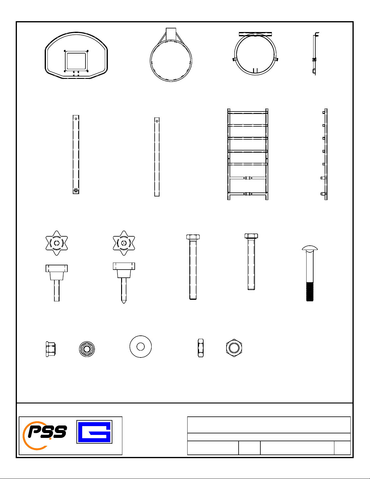
ITEM (1)
BACKBOARD
ONE EA.
ITEM (2) & (3)
GOAL AND NET
ONE EA.
ITEM (4)
UPPER FRAME ASSEMBLY
ONE EA.
ITEM (5)
LOWER FRAME CONNECTOR
ONE EA.
ITEM (7)
HAND KNOB M12 X 50mm
TWO EA.
ITEM (12)
M8 FLANGE NUT
TEN EA.
ITEM (6)
UPPER FRAME CONNECTOR
ONE EA.
ITEM (8)
HAND KNOB M12 X 60mm
TWO EA.
ITEM (11)
M8 FLAT WASHER
SIX EA.
ITEM (9)
HEX HEAD M8 X 70mm
FOUR EA.
ITEM (15)
M12 JAM NUT
TWO EA.
BACKBOARD FRAME ASSEMBLY
ITEM (10)
HEX HEAD M8 X 60mm
SIX EA.
ITEM (14)
ONE EA.
ITEM (13)
CARRIAGE BOLT M8 X 60mm
FOUR EA.
PERFORMANCE
SPORTS SYSTEMS
GARED
Installation and Assembly Instructions
Gared Holdings, LLC
9200 E. 146th St.
TM
Noblesville, IN 46060
FILE LOC.
DATE
3/14/2019
ADJUSTABLE JUNIOR JAMMER
Q:\Inventor Files\_xxxx-xx-xx\JJ5 MODEL
SHT. NO. PART NO. REV
3
OF 6
JJ5A
B
Page 4
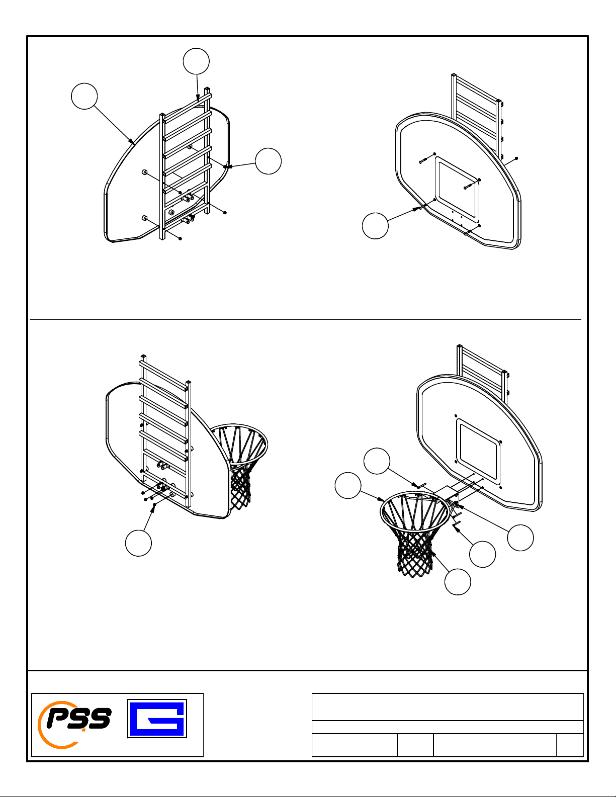
14
1
12
13
STEP ONE
Using carriage bolts M8x60mm (13) and M8 flange nuts (12), assemble backboard frame assembly (14) to backboard (1).
9
2
12
11
10
3
STEP TWO
Assemble net (3) to goal (2), then assemble goal (2) to backboard (1) using hex head M8x70mm (9) on top two holes
and hex head M8x60MM (10) on bottom two holes of goal with M8 flat washers (11) and M8 flange nuts (12) as shown in detail.
Installation and Assembly Instructions
ADJUSTABLE JUNIOR JAMMER
Q:\Inventor Files\_xxxx-xx-xx\JJ5 MODEL
SHT. NO. PART NO. REV
4
OF 6
JJ5A
PERFORMANCE
SPORTS SYSTEMS
GARED
Gared Holdings, LLC
9200 E. 146th St.
TM
Noblesville, IN 46060
FILE LOC.
DATE
3/14/2019
B
Page 5
7
B B
5
SECTION B-B
12
12
4
11
6
9
7
11
9
Hand knob must safely secure the ladder frame to the upper frame. Make sure the
hand knob is securely tightened in order to properly hold the ladder frame in place.
Failure to secure hand knob in position could allow the ladder frame to come out of the
track and fall causing damage to equipment and/or serious injury to personnel.
STEP THREE
Assemble lower frame connector (6) to backboard frame assembly (14) using hex head M8x70mm (9).
Assemble upper frame connector (5) to upper frame assembly (4) using hex head M8x70mm (9),
M8 flat washer (11) and M8 flange nut (12) as shown above.
Install hand knob (7) on upper frame connector (6) and upper frame assembly (4)
Installation and Assembly Instructions
ADJUSTABLE JUNIOR JAMMER
Q:\Inventor Files\_xxxx-xx-xx\JJ5 MODEL
PERFORMANCE
SPORTS SYSTEMS
GARED
Gared Holdings, LLC
9200 E. 146th St.
TM
Noblesville, IN 46060
FILE LOC.
DATE
3/14/2019
SHT. NO. PART NO. REV
5
OF 6
JJ5A
B
Page 6
7 FT
A
EXISTING BACKBOARD
AND GOAL
EXISTING BACKBOARD
AND GOAL
7 1/2 FT
8 1/2 FT
USE UPPER ANCHOR
POSITION FOR 7 FT HEIGHT
8 FT
9 FT
SEE
WARNING
SHEET 5
8
DETAIL A
ADJUST BRACE TO
PLUMB BACKBOARD AND
LEVEL GOAL
15
USE LOWER ANCHOR
POSITION FOR 9 FT
THROUGH 7 1/2 FT HEIGHT
Hand knobs must safely secure the upper frame to the existing goal. The point of the
hand knob MUST contact the goal beneath the welded support flange or goal rim in
order to properly lock in place.
Failure to secure hand knobs in position could allow the unit to fall causing damage to
equipment and/or serious injury to personnel.
With the help of an assistant, place assembled unit onto permanent goal hoop. Ensure lower frame connector (5)
is engaged with upper frame connector (6) as shown in illustration, insert and tighten hand knob M12 x 50mm (7).
PERFORMANCE
SPORTS SYSTEMS
STEP FOUR
Secure unit into place as shown in detail “A” and fully tighten hand knob M12x50mm (7)
and secure with jam nut M12 (15) on both sides.
Installation and Assembly Instructions
ADJUSTABLE JUNIOR JAMMER
Q:\Inventor Files\_xxxx-xx-xx\JJ5 MODEL
SHT. NO. PART NO. REV
6
OF 6
GARED
Gared Holdings, LLC
9200 E. 146th St.
TM
Noblesville, IN 46060
FILE LOC.
DATE
3/14/2019
JJ5A
B
 Loading...