

Page 1
MIS TP 125/E
N1/0701
OPERATION,
AINTENANCE
and
INSTALLATION
MANUAL and
PARTS LIST
ROTARY
LOBE
PUMP
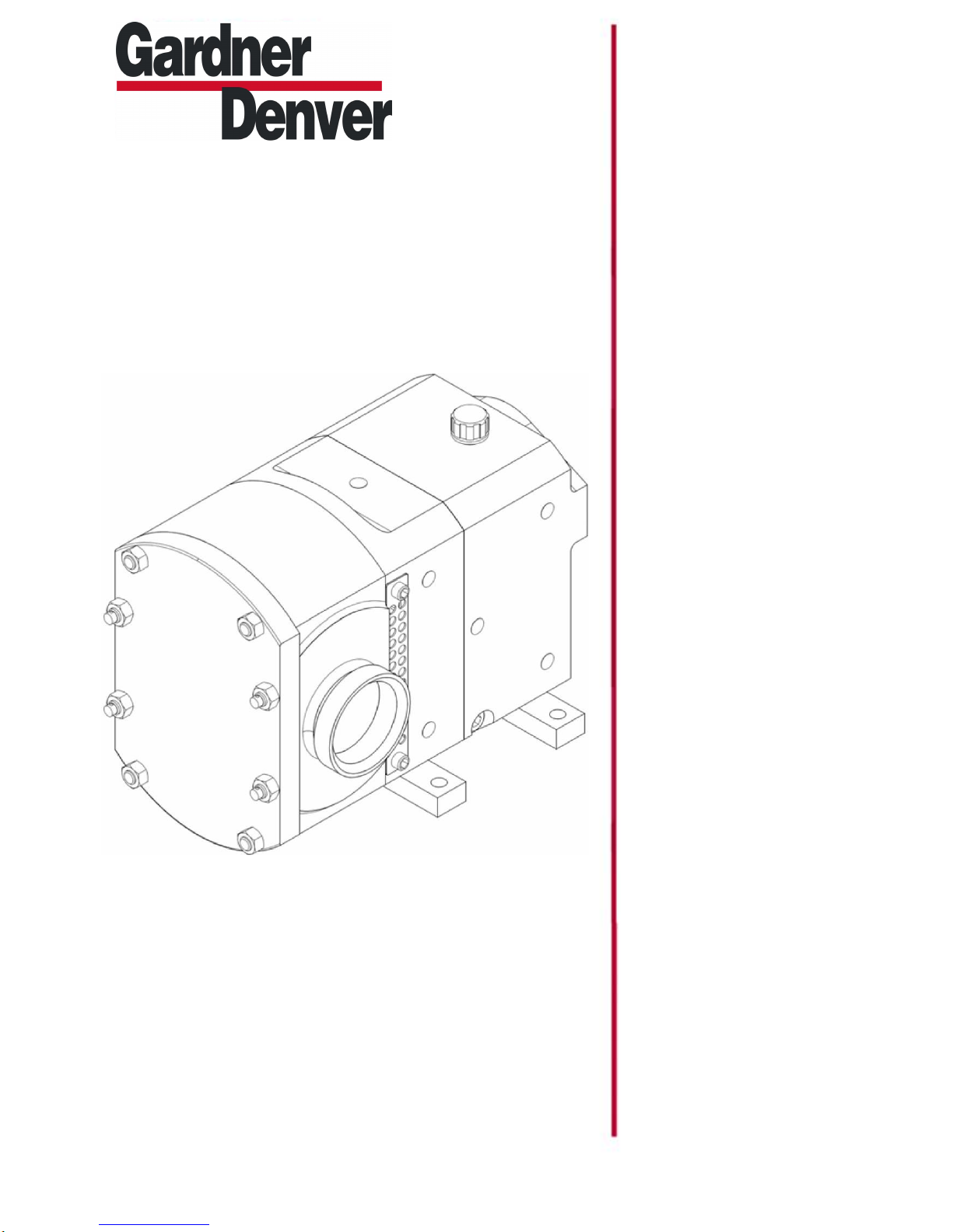
STP 125
STP125
VERSION: 03
February 3, 2015
Page 2

Page 3

1.2
Duty
conditions
1 1.3 Noise
levels
1 1.4
Utility
requirements
1 1.5 Safety
precautions
2 1.6
Health
and safety
information
3
4
2.2 Unpacking
2.3 Handling
4
2.4
Pump
storage
3.2
Principle
of
operation
5 3.3
Pump
dimensions
6 3.4 Pump
weight
6 3.5
Pump
displacement
6 3.6 Pump
information
chart
6 3.7 Pressure
relief
valve
7
4.2
Direction
of
rotation
4.3 Pipework
8
4.4
Port
orientation
STP125 Page
1
1.0 General
Page No
1.1 Pump limits of application or use
2.0 Unpacking, handling and storage
2.1 Documents
3.0 Description of pump or pump unit
3.1 General pump description
1
4
4
5
4.0 System Design and Installation
4.1 System design advice
5.0 Commissioning
5.1 Lubricating the pump
5.2 Recommended lubricants
5.3 Changing the oil
5.4 Oil capacity
6.0 Start Up, Shut Down and Cleaning in Place
6.1 Pump start up checklist
6.2 Pump shut down procedure
6.3 Cleaning in Place (CIP)
6
7
8
9
9
9
9
10
11
12
Page 4

7.2
Recommended
spare
parts
7.3
Maintenance
tools
8.2
Removing
the front
cover
8.3
Removing
the rotors
8.4
Product
seal
removal
8.5
Removing
the rotorcase
8.6
Removing
the shaft
sleeves
and shims
8.7
Draining
the pump
of
lubricant
8.8
Removing
the front
seal
retainers
8.9
Removing
the gear
housing
8.10
Removing
the timing
gears
8.11
Shaft
and bearing
removal
9.2
Fitting
the front
seal
retainers
9.3
Fitting
timing
gears
and setting
rotor
timing
9.4
Adjusting
the rotor
timing
9.5
Fitting
the gear
housing
9.6
Setting
the rotor
clearances
9.7
Fitting
the seal
9.8
Fitting
the rotors
9.9
Fitting
the front
cover
STP125 Page
2
7.0 Maintenance and inspection
Page No
7.1 Maintenance schedule
8.0 Disassembly
8.1 Before dismantling the pump
9.0 Assembly
9.1 Fitting shafts into the bearing housing
13
13
13
14
15
15
15
15
16
16
16
16
16
16
17
17
17
18
18
19
19
19
19
10.0
Replacing 'O' ring seal
10.1 Product 'O' ring seal replacement
10.2 'O' ring seal fitting
10.3 To remove the seal housing
10.4 Seal housing fitting
11.0 Replacing mechanical seal
11.1 Single mechanical seal
11.2 Single mechanical seal removal
.
20
20
20
20
21
21
Page 5

Operatio
n Manual
STP125 Page
3
11.3 Single mechanical seal fitting
12.0 Pump heating tank
12.1 Heating tank removal
12.2 Heating tank fitting
13.0 Relief valve
13.1 Disassembly - relief valve
13.2 Assembly - relief valve
14.0 Faults, causes and remedies
15.0 Torque settings/spanner sizes
16.0 Exploded view drawing and parts list
Page No
22
23
23
24
24
25
26
28
Page 6

Operatio
n Manual
STP125 Page
3 STP125 Page
4
1.0 General
1.1 Pump limits of application or use
This pump has been designed for pumping
a range of viscosities from water to semisolid, suitable for both homogeneous liquids
and liquids with non abrasive particles/
solids in suspension.
Speeds to 1000rpm and temperatures to
158°F can be accomodated on this pump.
These conditions cannot always be
accomodated simultaneously.
The STP125 has been designed to operate
at a maximum continuous discharge pressure
of 145 psi. However the STP125 is capable
of withstanding discharge pressures up to a
maximum of 160 psi intermittently. At
pressures above 145 psi there is the
possibility of leakage from the primary seal, if
this occurs and the seal continues to leak at
pressures below 145 psi it is an indication
that the primary seal may have been
permanently damaged and should therefore
be replaced at the earliest opportunity.
Continous operation at pressures above 145
psi will result in premature failure of the
pump.
If the user has not specified the pumping
application or needs to change it, it is
important to confirm that the materials of
construction and product seals are
compatible with the pumping application
and that adequate NPSH is available.
For specific guidelines contact your supplier
quoting pump serial number, system and duty
details. (e.g. media, pressure(s), flowrate,
pumping temperatures etc).
1.2 Duty conditions
The pump should only be used for the duty
for which it has been specified. The
operating pressure, speed and temperature
limits have been selected at the time of order
and MUST NOT be exceeded.
These details are stated on the original
documentation and if not available may be
obtained from your supplier quoting pump
serial number.
1.3 Noise levels
Under certain operating conditions pumps
and/or drives and/or the systems within
which they are installed can produce sound
pressure levels in excess of 85dBA. When
necessary personal protection against noise
should be taken to safeguard the hearing of
persons who are likely to be in close
proximity to the equipment.
1.4 Utility requirements
Electrical supply:-
This pump may be supplied bareshaft or
coupled to an electric motor.
Hydraulic supply:-
This pump may be coupled to a hydraulic
motor.
Temperature control:-
Temperature control jackets will require
appropriate hot or cold media supply i.e. oil/
water/steam.
Page 7
Operatio
n Manual
1.5 Safety precautions
All warnings in this manual are summarised
on this page.
Pay special attention to the instructions
below so that severe personal injury or
damage to the pump can be avoided.
Personnel performing installation, operation
and maintenance of the pump must have the
relevant experience required.
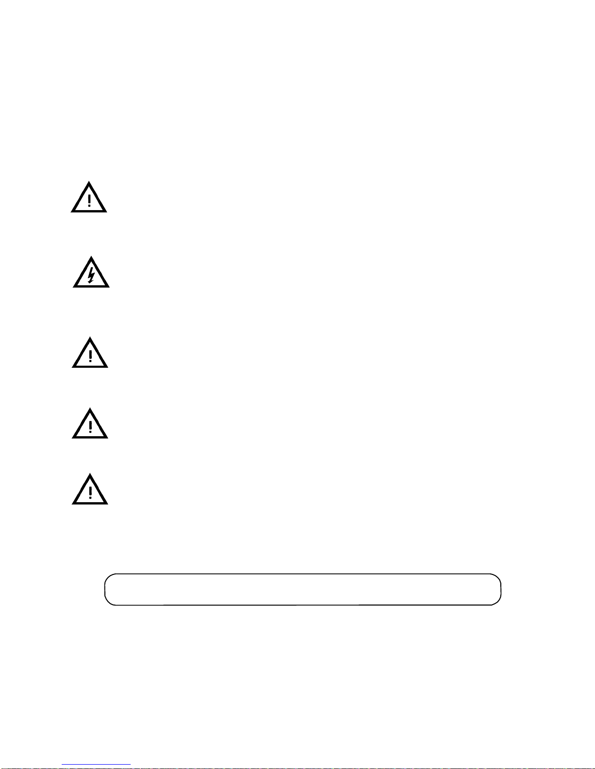
Warning Signs
General safety instructions are
preceded by this symbol.
Electrical safety instructions
are preceded by this symbol.
Take great care when using
caustic agents.
Installation
Operation
Always observe the technical data.
Never touch the pump or the pipelines
when pumping hot liquids or when
sterilising.
Never stand on the pump or pipelines.
Never run the pump with the suction
side and/or the pressure side blocked.
Always handle toxic and acidic liquids
with great care.
Never put your hands or fingers inside
Maintenance
the pump or port connections.
Always observe the technical data.
Alw ays secure the pump during
maintenance and transportation.
Always observe the technical data.
The pump must be electrically
connected by authorised personnel.
(See the motor instructions supplied
with the drive unit).
Never start in the wrong direction of
rotation with liquid in the pump.
Never put your hands or fingers
inside the port connections
Always disconnect the pump from the
drive unit and power supply when
servicing the pump.
The pump must never be hot when
servicing it.
The pump and pipelines must never
be pressurised when servicing the
pump.
Never put your hands or fingers inside
the port connections.
Study this manual carefully
Page 8

Operatio
n Manual
STP125 Page
6
1.6 Health and safety information
Potential safety hazards
The following section gives information on
handling, storage and disposal of parts and
materials used in the pumps which may be
considered hazardous to health.
Please pass this information on to your
Safety Officer, he may need it to comply with
Health and Safety, and COSHH regulations.
General first aid
If potentially hazardous substances are
accidentally inhaled, or skin or eyes
contaminated, then the following basic
precautions should be taken
Inhalation - Move to fresh air
Skin - Wash with soap and water
Eyes - Flush with water, seek medical
attention
In all cases, if symptoms persist, seek medical
attention.
Material
SILICONE SEALANT GEARBOX SEAL RETAINERS,
GENERAL SEALANT.
ANTI-SEIZE COMPOUNDS BEARINGS APPLIED FROM AEROSOL.
OIL AND GREASE OIL - GENERAL LUBRICATION
GREASE - PRODUCT SEALS,
TIMING GEARS, GENERAL
LUBRICATION.
PLASTIC COMPOUNDS (PTFE,
POLYPROPLYENE, PVC)
ELASTOMERIC COMPOUNDS
(EP, VITON, NITRILES, PTFE)
PAINT EXTERNAL PUMP SURFACES. RELEASES DUST AND FUMES
PTFE - 'O' RINGS, LIP SEALS
'O' RINGS, LIP SEALS
Use
Major hazard
RELEASES VAPOUR AT ROOM
TEMPERATURE.
RELEASES VAPOUR. DISPOSE
OF CONTAINER AS IF
PRESSURISED.
SKIN AND EYE IRRITANT.
RELEASES FUMES WHEN
HEATED.
RELEASES FUMES WHEN
HEATED.
IF MACHINED. TREAT AS A
FIRE HAZARD.
Page 9
Operatio
n Manual
STP125 Page
7
2.0 Unpacking, handling and storage
To avoid any problems, on receipt of your pump
always use the following procedure:-
2.1 Documents
1. Check the delivery note against the goods
received.
2.2 Unpacking
Care must be taken when unpacking the pump,
and the following stages must be completed:-
1. Inspect the packing for any possible signs
of damage in transit.
2. Carefully remove the packing.
3. Inspect the pump for any visible signs of
damage.
4. Remove packing from the pump port
connections.
5. Ensure that any additional equipment such
as seal flushing pipework is not damaged.
2.3 Handling
Refer to the pump weights guide, prior to using
any lifting gear. Use the correct lifting slings
for the pump weight.
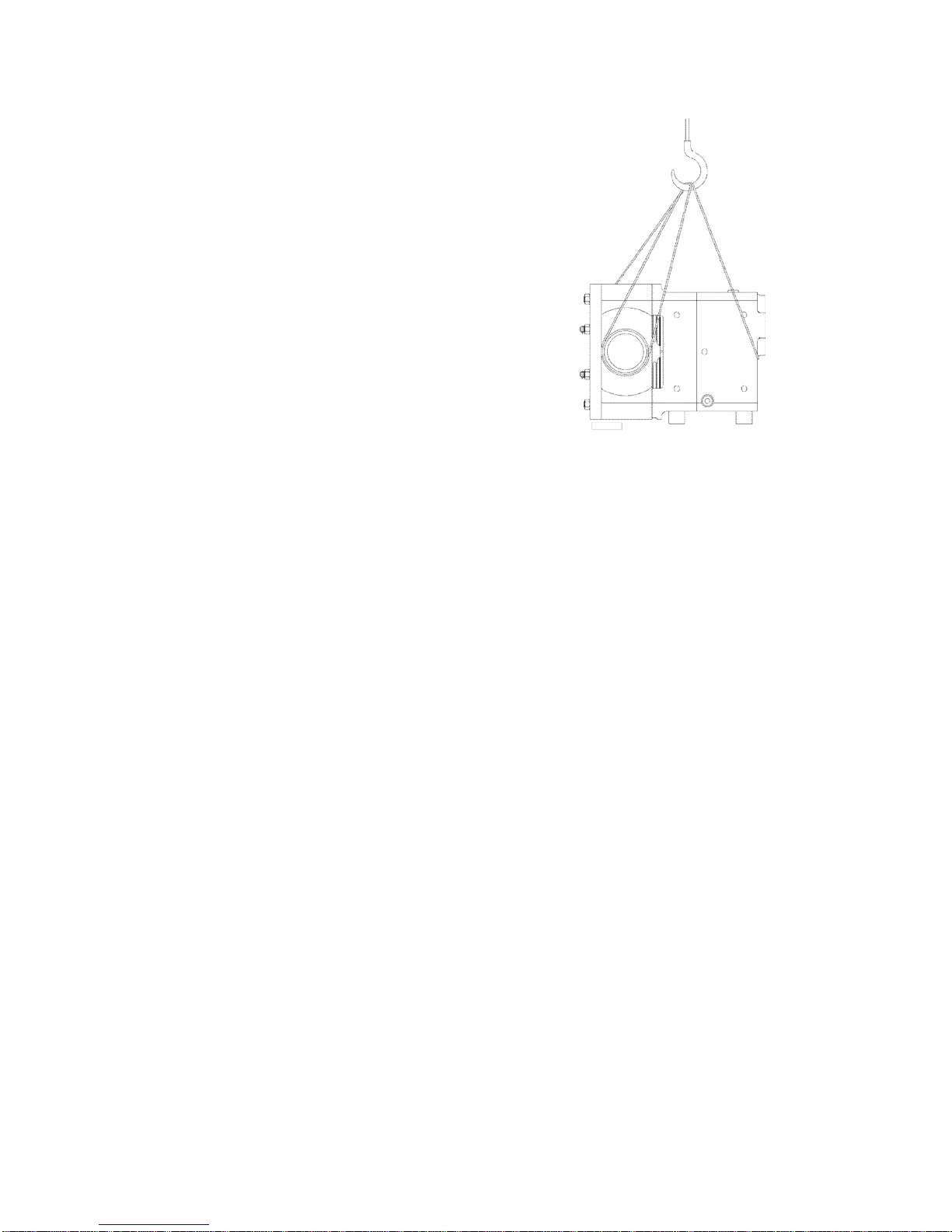
An M10 x 15 tapping has been provided
suitable for the fitting of an eyebolt to enable
the pump to be lifted either with or without
the hydraulic drive fitted. Alternatively slings
should be wrapped around the ports and the
hydraulic drive flange.
Note : To stop the slings slipping always cross
the slings at the lifting hooks.
Bareshaft pump
2.4 Pump storage
After receipt and inspection if the pump is not
to be installed immediately the pump should
be repacked and placed in suitable storage.
The following points should be noted:-
1. Plastic or gasket type port covers
should be left in place.
2. Pumps received wrapped with
corrosion inhibiting treatment material
should be re-wrapped.
3. A clean, dry storage location, free from
vibration should be selected. When a
moist dusty atmosphere must be used
for storage, further protect the pump or
unit with a moisture repellent cover until
it is to be installed.
4. Rotate pump by hand, weekly, to
prevent bearing damage.
5. All associated ancillary equipment
should be treated similarly.
Page 10
Operatio
n Manual
STP125 Page
8
3.0 Description of pump or pump unit
3.1 General pump description
The pump supplied is a positive
displacement pump, which may be supplied
bare shaft (see below) or with a drive unit .
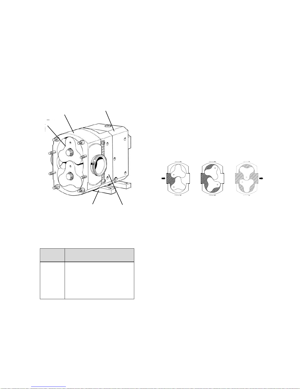
The drawing below indicates various parts of
the pump.
B
A
D
3.2 Principle of operation
The pumps are of the positive displacement
rotary type with trilobe rotors. The direction
of flow is reversed by changing the direction
of rotation of the pump's drive shaft. The
pumping principle is as follows.
The volume at the inlet increases when the
rotors rotate and the product is drawn into
the pump. It is then transported in the space
between the lobes and the periphery of the
rotorcase to the discharge side, where volume
between the rotors is reduced and the product
is discharged.
E
C
Bareshaft pump
Item
A
B
C
D
E
Description
Rotors
Rotorcase
Bearing Housing
Gear Housing
Feet
Page 11
Operatio
n Manual
STP125 Page
9
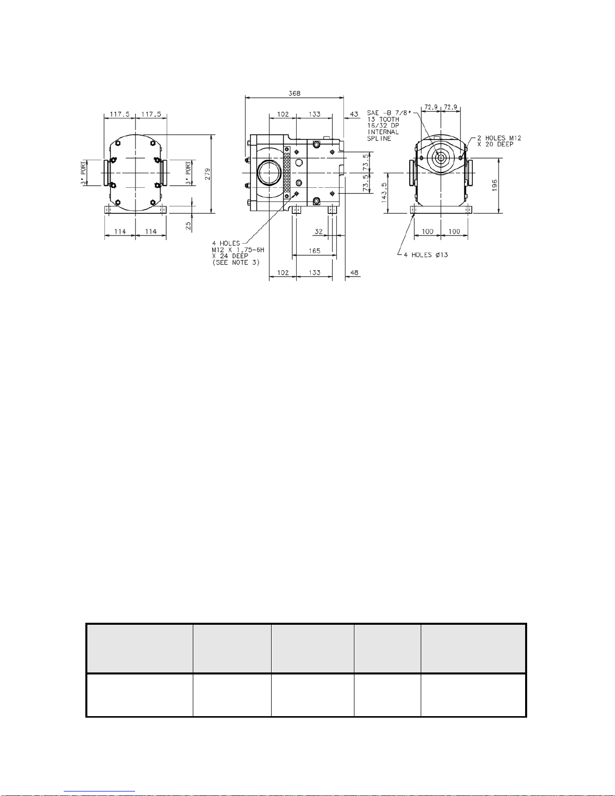
3.3 Pump dimensions - horizontally ported pump
The above dimensions are for guidance only
and should not be used for installation
purposes. Certified dimensions are available
upon request.
3.4 Pump weight
Pump weight (dry) with plain cover 139 lb.
Pump weight (dry) with relief valve 147 lb.
The above weights are for guidance only
and will vary depending upon the
specification of the pump.
3.5 Pump displacement
Pump displacement per revolution is
0.28 US gall.
3.6 Pump information chart
Pump Max flowrate
(US gall/min)
3.7 Pressure relief valve
A integral relief valve is available. It can be
used regardless of the direction of rotation. A
manual override is also available.
The relief valve is designed to partially
protect the pump from damage caused by
over-pressurisation. The relief valve is preset
at 145 psi.
Over pressurisation can occur if :-
1. A valve is closed against the pump
discharge.
2. The product viscosity in the system is
significantly increased.
3. The pump speed is increased.
Max pressure
(psi)
Max speed
(rev/min)
Max Pressure at
max CIP Temp
of 266
0
F (psi)
STP125
280
145
1000
45
Page 12
Operatio
n Manual
STP125 Page
10
4.0 System design and installation
4.1 System design advice
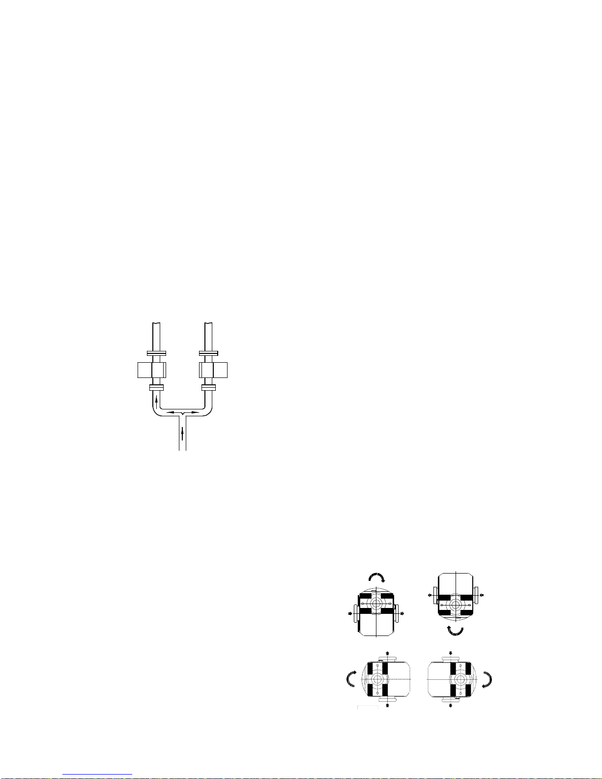
When designing the pumping system :Do - Confirm with the supplier the Net
Positive Suction Head (NPSH)
requirements for the system, as
this is crucial for ensuring the
smooth operation of the pump and
preventing cavitation.
Do - Avoid suction lifts and manifold/
common suction lines for two
pumps running in parallel, as this
may cause vibration or cavitation.
Discharge Line
Plan View
Suction Line
Do - Protect the pump against blockage
from hard solid objects e.g. nuts,
bolts etc. Also protect the pump
from accidental operation against
a closed valve by the use of relief
valve, pressure switch, etc..
Do - Fit suction and discharge pressure
monitor points as close to the pump
ports as possible for diagnostic
purposes.
Do - Install a non-return valve to prevent
turbining when high pressures are
applied to the pump whilst it is not
in use.
Do - Install valves if two pumps are to be
used on manifold/common
discharge lines.
Do - Make the necessary piping
arrangements if steam is required
for heating /cooling tanks.
Do not- Subject the pump to rapid
temperature changes during C.I.P.
(Cleaning in Place) procedures.
Pump seizure can result from
thermal shock. A suitable by-pass
is recommended.
4.2 Direction of rotation
The direction of flow is dictated by the
direction of rotation of the drive shaft.
Reversing the direction of rotation will
reverse the flow direction.
Page 13
Operatio
n Manual
STP125 Page
11
4.3 Pipework
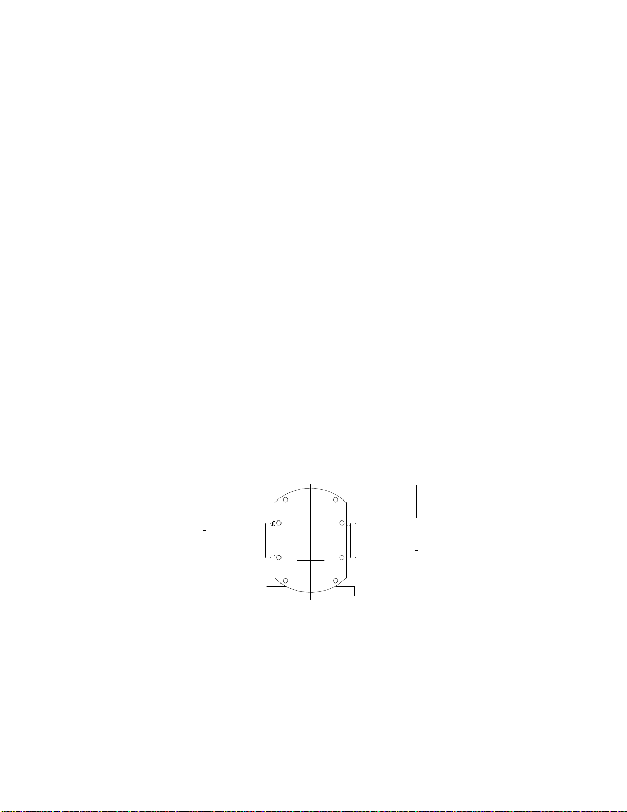
All pipework must be supported. The pump
must not be allowed to support any of the
pipework weight.
Remember - Pipework supports must also
support the weight of the
product being pumped.
Always :Have - Suitably sized short straight
suction lines to reduce
friction losses in the
pipework thereby improving
the NPSH available.
Avoid - Bends, tees and any
restraints close to either
suction or discharge side of
pump. Use long radius
bends wherever possible.
Provide - Valves on each side of the
pump to isolate the pump
when necessary.
Pipework
4.4 Port Orientation
The pump can be mounted in either horizontal
or vertical port orientation by changing the
pump mounting feet and its position. Pump
should not be side mounted when fitted with
vertically ported feet.
support
Keep - Pipework horizontal where
applicable to reduce air
locks. Include eccentric
reducers on suction lines if
required.
Check - Coupling alignment during
installation.
Use - Flexible connections between
tank pipework and suction
port where conditions allow.
Pipework
support
Page 14

Operatio
n Manual
Pum
p
Porting US Ga
ll.
STP125
Horizontal 0.4 STP125
Vertical 0.25
STP125 Page
12
5.0 Commissioning
When taking delivery of a new or refurbished
pump unit it is essential to check that the
gearbox is filled with the correct quantity of oil
to the centre of the sight glass, with one of the
recommended grades of lubricant in the table
below. Failure to have the correct grade and
level of oil in the gearbox prior to installation
and start-up, could result in serious damage
to the internal components.
The oil filler cap does not require to have
vent/breather hole. Using this type of solid
filler cap prevents the ingress of dirt and
cleaning solutions that would contaminate
the lubricant and reduce or destroy its
effectiveness . If this cap is lost at any time it
is important that a replacement of the same
type is fitted immediately.
5.1 Lubricating the pump
The gearbox should be filled to the mid point
of the sight level glass. This requires
approximately 0.4 US gall of oil for a
Horizontally ported pump and 0.25 US gall for
a Vertically ported pump.
5.2 Recommended lubricants
5.3 Changing the oil :-
The pump will not be supplied oil filled.
First change - After 150 hours of operation
or after 1 month, whichever comes first.
Subsequent changes - Every 3000 hours of
operation or annually, whichever comes first.
Only use the recommended oil types.
5.4 Oil capacity
Model
Make
Grade
-4°F +266°F
BP Energol
Castrol Alpha
Mobil Gear
Shell Omala
Texaco Meropa
Esso Spartan
If none of the above manufacturers grades
are obtainable a suitable alternative high
grade 80-90 gear lubricant may be used
GR-XP150
SP150
629
150
150
150
Page 15

Operatio
n Manual
STP125 Page
13
6.0 Start up, shut down and Cleaning in Place
6.1 Pump Start Up Check List
1. Has the pipework system been flushed
through to purge welding slag and/or
any other hard solids?
2. Have all obstructions been removed
from the pipework or pump?
3. Are the pump connections and
pipework joints tight and leak-free?
4. Is there lubrication in the pump and
drive unit?
5. Are the pipework valves open?
6. Are all safety guards in place?
7. Start then stop the pump to check that
the product is flowing in the correct
direction?
8. Are the pump speed/pressure and
temperature settings below the pump
maximum limitations?
When all answers are 'yes', the pump
may be used.
If there are any pumping problems refer to the fault finding chart
Yes No
Page 16

Operatio
n Manual
STP125 Page
14
6.2 Pump shut down procedure
1. Turn the pump off.
2. Isolate the pump/drive from all power
and control supplies.
3. Close the pipework valves to isolate
the pump.
4. Ensure all auxiliary services such as
heating/cooling tanks supply etc. are
isolated.
5. If the pump is to be dismantled, refer to
section 8 of this manual.
Page 17

Operatio
n Manual
STP125 Page
15
6.3 Cleaning In Place (CIP)
The pump can be manually cleaned or
cleaned in place(CIP). The following is an
example of a typical CIP procedure. Specific
requirements for each application should be
dictated by the carrier/shipper.
Determine last product handled by the
pump
Remove the dust caps and/or fittings
from the pump, rinse any residue from
them with hot water.
Connect hot water hose to the pump
inlet or connect pump inlet to the tank
trailer outlet valve during the tank’s
hot water cleaning cycle.
When not fitted connect a ball or gate
valve (to restrict liquid flow) to the
pump discharge outlet.
If driven hydraulically, ensure that the
hydraulic proportional control valve is
in the neutral position.
If driven hydraulically or electric/
hydraulically, start system and run at
normal operating speed. Open the
ball or gate valve on the pump
cleaning system so the hot water or
cleaning solution from the tank flows
into the pump. (hot water should be
176°F to 194°F) If hydraulically driven,
select forward on the proportional
control valve and slowly increase (by
pushing the handle) to full pump speed.
When driven electrically start the
system and slowly increase the speed
with the handwheel on the belt variator.
Using the ball or gate valve, (to
restrict liquid flow) increase the pump
pressure to approximately 60-75 psi
while it is operating. A pressure gauge
at the discharge outlet will be required.
This will ensure that the cleaning
solution is cleaning the pump under
high pressure conditions.
Run the pump for 15 minutes under this
pressure.
Relief Valve Pumps Only
WARNING: Do not complete this next
step if your pump does not have a
relief valve !!
Close the ball or gate valve (to restrict
liquid flow) until the pump relief valve
actuates. Open the valve and close it
again. Open valve once again - this
should have now cleaned any residue
from behind the relief valve diaphragm
and any other close tolerance areas
inside the pump.
Shut down pump system in reverse
order of above.
Clean all external fittings from the
fittings box with hot water and return.
Remove all hose and fittings from the
IMPORTANT
Do not subject the pump to rapid temperature
changes as pump seizure can result from thermal
shock.
pump, bag ends and seal the ports.
Page 18
Operatio
n Manual
STP125 Page
16
7.0 Maintenance and inspection
7.1 Maintenance schedule
It is advisable to install pressure gauges on
both sides of pump as close as possible to the
ports so that any problems within the pump/
pipework will be highlighted.
Your weekly schedule should include:
Checking the oil level in the gearcase
Checking the product seals for leakage
and replace as necessary. The pump
has been designed to operate at a
maximum continuous discharge
pressure of 145 psi. However, it is
capable of withstanding discharge
pressures up to a maximum of 160 psi
intermittently. At pressures above 145
psi there is the possibility of leakage
from the primary seal, if this occurs and
the seal continues to leak at pressures
below 145 psi, it is an indication that the
primary seal may be permanently
damaged and should therefore be
replaced at the earliest opportunity.
Checking the oil seals for leakage and
replace as necessary at the earliest
opportunity.
Check pumping pressures. In certain
operational circumstances the pump
will pose a thermal hazard and as such
should not be touched during operation.
After shutdown the pump unit should be
allowed time to cool.
7.2 Recommended spare parts
The following table details the recommended
spare parts that should be retained within
your maintenance schedule. (Refer to the
Exploded drawings and parts list in section 16
of this manual).
Part description
Description
'O' ring, product seal
or
Mechanical seal
'O' ring, seal housing
'O' ring, sleeve/shaft
'O' ring, sleeve/rotor
'O' ring, rotor nuts
'O' ring, front cover
Oil seal drive end
Oil seal gland end
Quantity
2
2
2
2
2
2
1
1
2
Refer to spare parts manual for
item numbers.
7.3 Maintenance tools
The following lists the maintenance tools
required when working on the pump.
Dismantling the pump head
You will need:
Spanners
Socket set
Plastic block
Soft mallet
Cleaning hose
Rotor removal tool (supplied
with pump)
6" Prybar (i.e. Snap-On Pt.
650)
Dismantling the gearbox
You will need - A fully equipped work shop in
addition to the above.
Page 19
Operatio
n Manual
STP125 Page
17
8.0 Disassembly
8.1 Before dismantling the pump
Before starting to dismantle the pump
Always:-
Purge -
the pump and system if any noxious/hazardous
products have been pumped.
Isolate -
pump/drive unit from all power and control
supplies.
Close -
pipework valves to isolate the pump
Disconnect -
the pump from the drive unit.
Secure -
The pump must be securely held during
maintenance to maintain stability.
Read this section before continuing to dismantle the pump
Page 20
Operatio
n Manual
STP125 Page
18
To aid re-assembly, note which components
came off which shaft. Good engineering practise
suggests that components removed from a
shaft should be assembled on the same shaft.
If removing the front cover for any reason
check that rotorcase retaining nuts are tight
before replacing.
8.2 Removing the front cover
1. Remove the 'R' clips (2) and carefully
loosen the front cover retaining nuts (3)
as there may still be residual pressure in
the system.
2. Remove the front cover nuts and take off
the cover (6). If stuck, loosen by tapping
with soft mallet at overlap at sides.
Do not lever off.
3. Flush out the pump head before
continuing.
4. Remove the 'O' ring (7) from the front
cover.
8.3 Removing the rotors
1. Insert a plastic block between the two
rotors (13) to stop them turning.
2. Using a spanner remove the rotor nuts
(9). These nuts have right hand threads.
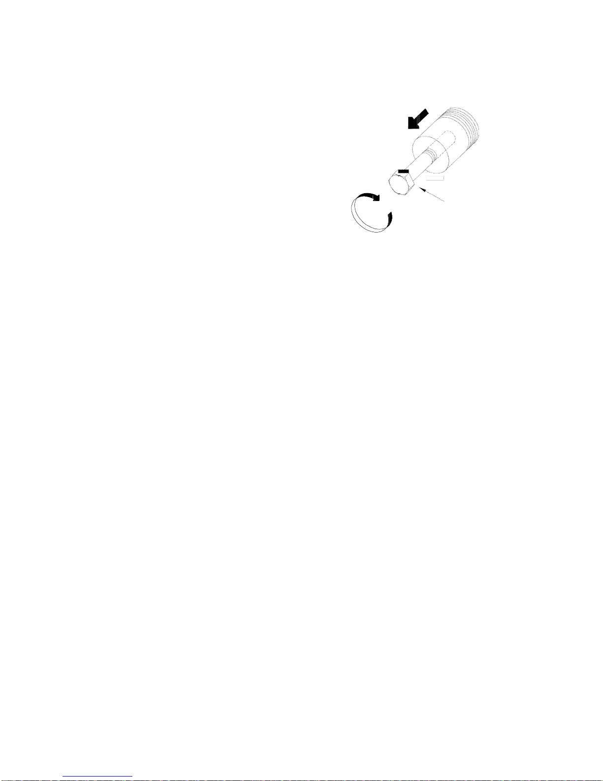
3. The rotors can be removed from the shafts
(28,29) by hand or by using the extractor
tool supplied with the pump to aid
disassembly. Unscrew the central bolt
until flush on the inside, screw the tool two
full turns into the rotor. Whilst preventing
the tool from turning screw in the central
bolt. The rotor is jacked off the shaft for
hand removal.
Central bolt
8.4 Product seal removal
1. 'O' ring- Refer to section 10
2. Mechanical Seal - Refer to section 11
8.5 Removing the rotorcase
1. Remove the rotorcase retaining nuts. (5).
2. Gently tap the rotorcase (11) on each side
with a soft mallet to release it from the
bearing housing. (18)
3. The rotorcase will be supported on
the studs (4) during removal.
4. The rotorcase and seal housing (66) can
be removed as an assembly.
Page 21

Operatio
n Manual
STP125 Page
19
8.6 Removing the shaft sleeves and shims
1. Remove the wire shaft sleeve retaining
clip (64) from the shaft taking care not to
damage the shaft spline or sleeve
abutment face.
2. Pull the shaft sleeve (42) off the shaft.
3. The setting ring (35) and shims (25) can
be removed from the shaft. Take care not
to lose or mix any shims and check no
shims are left inside the sleeve.
8.7 Draining the pump of lubricant
1. Remove the drain plug (51) from the gear
housing (14). The lubricant may now be
drained into a suitable container.
8.8 Removing the front seal retainer
1. Remove the seal retainers (36) by levering
with a screwdriver/lever.
2. Once the seal retainers are removed the
oil seals (37) can be removed using a
screwdriver/lever. It is essential to renew
the oil seals upon reassembly.
8.9 Removing the gear housing
1. Remove the socket head cap screws
(15).
2. Tap the foot of the bearing housing
assembly (18) gently to release the gear
housing (14) from the bearing housing.
3. Slide the gear housing (14) from the shafts.
Remove the bearing rear outer races (39)
and press out the oil seal (41). It is essential
to renew the oil seal upon re-assembly.
4. Remove the gasket. (17)
8.10 Removing the timing gears
1. Pull the rear inner bearing races (39) off
the shafts. A puller or extractor may be
required to do this.
2. Disengage the tabs of the lock washers
(52) fitted to the timing gear nuts (38) and
with a plastic block between the gears to
stop them turning remove the locking
nuts with a 'sharp tap' on a 'C' spanner.
3. Remove the timing gears (23,24), keys
(46) and any shims (30) from the shafts.
Note position of shims(top/bottom).
8.11 Shaft and bearing removal
1. Replace the rotors back on the shafts.
Disengage the tabs of the lock washers
(32) fitted to the bearing nuts (31) and with
the rotors locked by using a rag or similar
to stop them turning remove the locking
nuts with a 'sharp tap' on a 'C' spanner.
Remove the rotors from the shafts.
2. Disassemble shafts (28,29) from bearing
housing (18).
3. Remove each bearing set (33) (inner
cones and outer cups) and maintain in
sets if they are to be re-used.
To assist assembly note the positions on the
shaft from which the bearings were removed.
Good engineering practice suggests that if
bearings are removed from the shafts for any
reason they should be replaced with new
bearings.
Page 22

Operatio
n Manual
STP125 Page
20
9.0 Assembly
Assemble components to the shaft from which
they were removed.
9.1 Fitting shafts into the bearing housing
1. Locate the outer cups (33) into the bearing
housing (18). This operation is made
easier if the bearing housing is heated to
1580F. Press fit against the shoulders after
cooling.
2. Position the drive shaft (29) vertically in
the vice using soft jaws and apply antiseize
compound to the bearing diameters.
3. Heat the front bearing inner cones to 2300F.
Do not use any form of live flame when
heating as this will damage bearings.
4. Assemble the front bearing inner cone
(33) onto the shaft (29) ensuring a positive
fit against the shaft shoulder.
5. Locate the drive shaft assembly in the
bearing housing (18) in the bore marked
with an 'X' in the drainage slot.
6. Locate the second heated bearing on the
drive shaft and retain with the tab washer
(52) and bearing nut (38) (hand tight).
7. Repeat the operation for the auxiliary
shaft (28).
8. Allow bearings to cool to handling
temperature.
Note: Failure to do so will result in
incorrectly set bearings.
9. Secure the drive shaft (29) and tighten the
bearing lock nut (31), release the shaft,
lightly tap each end of the shaft with a soft
mallet and rotate.
Check the torque required to turn the
shaft in the bearings. The bearings
are correctly adjusted when the torque
to turn each shaft is 1.40 to 1.67 lbft for
new bearings.
If a torque wrench is not available tighten
until shaft is firm without spinning. Repeat
the above for the auxiliary shaft (28).
10. Lock the bearing retaining nuts (31) with
the tab washers (32). If no tab lines up with
any slot gradually tighten (never loosen)
until engagement is possible.
11. Apply oil to the bearings.
9.2 Fitting the front seal retainers
1. Lightly lubricate the outside diameter of
the oil seals (37) then press the oil seals
into the front seal retainers (36).
2. Clean the rear face of the retainers and
the mating faces on the bearing housing
(18). Apply silicone sealant to the
retainers and press into place.
9.3 Fitting timing gears and setting rotor
timing
1. Locate the timing shims (30) on each
shaft from which they were removed.
2. Locate gear keys (46) into shafts (28,29).
3. Slide each timing gear (23,24) onto the
shafts, realign marks if gears were
previously marked in pairs.
4. Locate tab of locking washer (52) in
keyway of each gear.
5. Fit the timing gear lock nuts (38) and with
a plastic block in the gears to stop them
turning tighten with a 'sharp tap' on a 'C'
spanner.
Page 23
Operatio
n Manual
STP125 Page
21
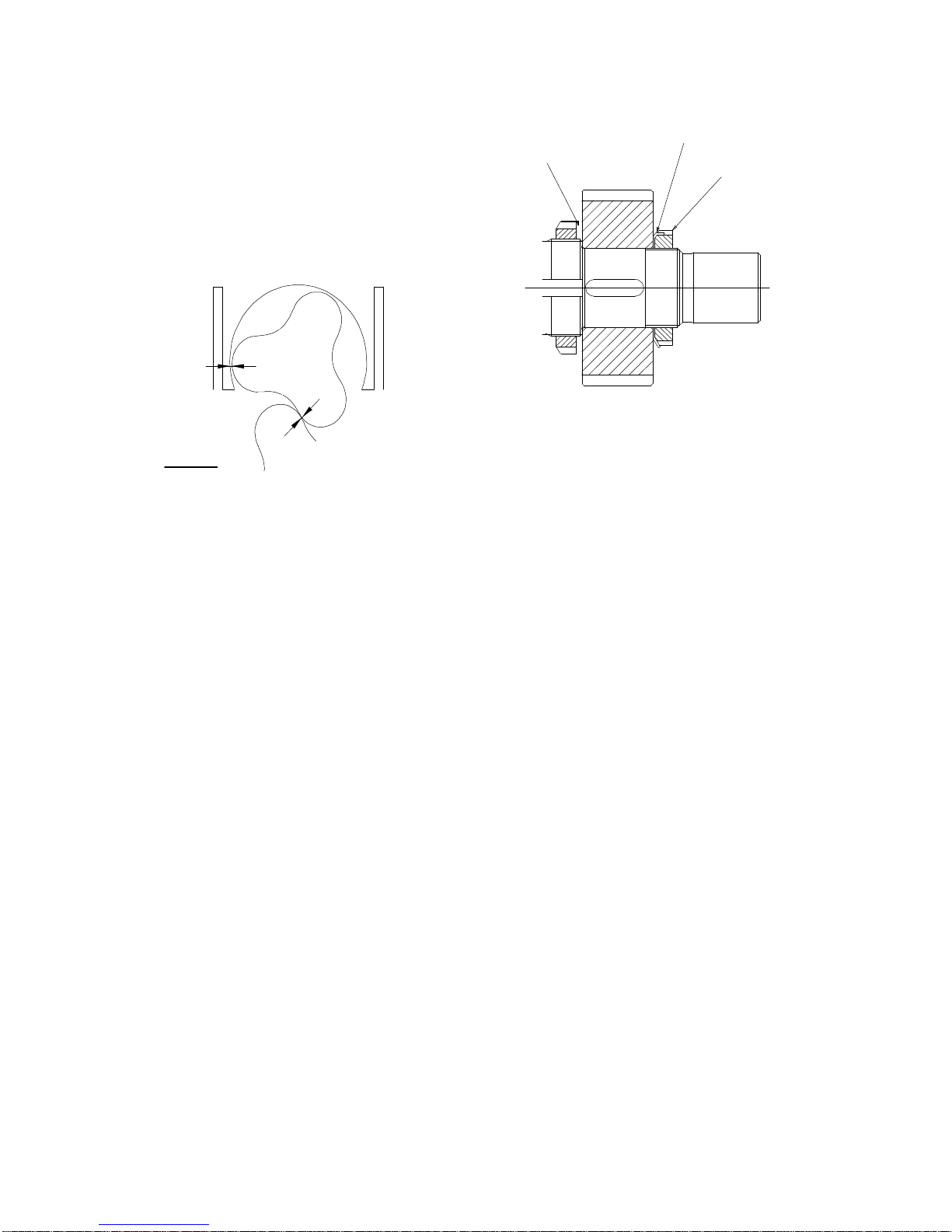
9.4 Adjusting the rotor timing
1. Slide rotors (13) onto the shafts (28,29),
but do not tighten the retaining nuts (9).
2. Turn the shaft so that the rotors are in the
position shown below.
Radial
Clearance
Mesh Clearance
(Make clearances
either side of the
lobe as near equal
as possible)
3. With the rotors loose on the shafts, using
feeler gauges measure between the
point indicated (mesh) whilst squeezing
the lobes together. Turn the shaft as
required to measure all six positions.
4. If the measurement points are unequal,
note the difference and which side of the
rotor has the larger clearance.
5. Correct the difference by adding or
removing shims (30) between the gear
face and shaft shoulder as indicated in the
diagram. Fully tighten the gear retaining
nuts and check the clearances are within
the specification limits. If correct, lock the
gear lock nuts (38) with the tab washer
(52).
6. Remove the rotors.
Shim
Tab washer
Gear locknut
9.5 Fitting the gear housing
1. Clean the gear housing (14) and heat to a
temperature of 1580F. Re-assemble the
bearing outers (39) into the housing. Allow
to cool to handling temperature then with
light lubrication to the outside diameter of
the oil seal (41) press into the housing.
2. Ensuring that the faces of the bearing
housing and gear housing are clean, fit
new gasket (17) to bearing housing.
3. Carefully slide the gear housing over the
shaft ensuring the oil seal is not cut or
damaged. Tighten the socket head cap
screws (15) to a torque figure of 33 lbft.
Page 24

Operatio
n Manual
STP125 Page
22
9.6 Setting the rotor clearances
Incorrect setting of the rotor
clearances will damage the pump.
1. Fit the rotorcase (11) and retain with four
nuts (5) tightened to 30 lbft.
2. Fit the setting ring (35) with chamfer towards
the shaft shoulder and 0.020 inch of shims
onto the shaft. At this point, do not fit 'O'
rings (45). Slide shaft sleeve onto the shaft
ensuring that the drivepin locates in any
position other than the missing spline.
3. Fit the rotors (13) and torque the retaining
nuts (9) to 110 lbft.
4. Using a micrometer and feeler gauges
measure the front and back clearances
respectively.
5. Adjust the shims (25) if necessary to ensure
the front and back clearances are within
the specified limits.
6. Check the radial clearances are within
specification limits.
7. If all clearances are correct, remove rotors,
shaft sleeves and rotorcase taking
care not to disturbe the shims.
8. Lightly grease the seal sleeve 'O' rings (45)
and fit to the sleeve.
9. Fit the sleeves onto the shafts ensuring that
the drive pins locate in any other position
than the missing spline.
10. Fit the seal sleeve retaining clips (64) onto
the shafts.
11. Fit the rotorcase (11) and retain with four
nuts (5) tightened to 30 lbft.
9.7 Fitting the seal
O'ring - Refer to section 10
Mechanical Seal - Refer to section 11
9.8 Fitting the rotors
1. Align the rotor with the missing spline of
the shaft.
2. Lubricate the rotor nut sealing 'O' (10)
ring and fit to the nut groove.
3. Use a plastic block between the rotors to
stop them turning while tightening the
rotor nuts (9) to 110 lbft.
4. To check that the rotors are correctly
synchronised turn the pump by hand, and
check the meshing clearances with feeler
gauges through all six points.
9.9 Fitting the front cover
1. Fit the front cover 'O' ring (7).
2. Fit the cover (6) onto the rotorcase studs
(4) and tighten the front cover nuts to the
recommended torque - 30 lbft. Fit 'R' clips
(2).
3. The pump can now be mounted with its
drive unit.
4. Prior to start up the pump must be
filled with oil.
Read the start-up check list before
proceeding to start the pump,
see section 6.1
Page 25
Operatio
n Manual
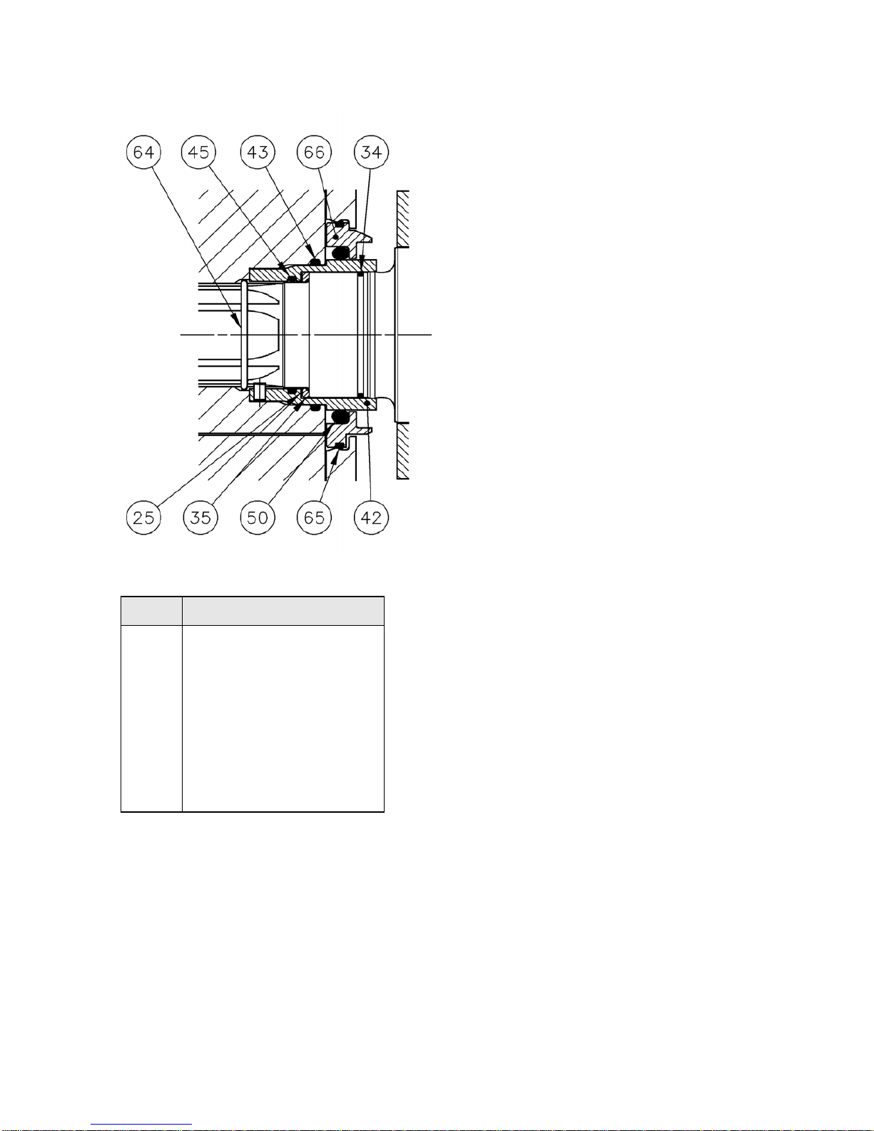
ITEM
DESCRIPTION
10 Replacing 'O'Ring Seal
25
34
35
42
43
45
50
65
66
Shim Pack
'O' Ring Shaft
Setting Ring
Shaft Sleeve
‘O’Ring Sleeve/Rotor
‘O’Ring Shaft/Sleeve
‘O’Ring Product
‘O’Ring Seal Housing/Rotorcase
Seal Housing
10.1 Product 'O'ring seal replacement
1. The product 'O'ring (50) can be
removed from the front of the
pump with a screwdriver or similar
tool once the rotor retention nut (9)
and rotor (13) are removed. Take care
not to damage the sleeve surface.
10.2 'O'ring seal fitting
1. Press a new product 'O'ring fully into
the seal housing (66), replace the rotors
and rotor retention nuts. To aid seal
fitting water may be used to lubricate the
'O'ring.
10.3 To remove the seal housing
1. Remove the gland guards (21).
2. Thoroughly clean the inside and
outside of the seal area on the
rotorcase and the bores of the rotor.
3. Remove the product 'O'ring (50).
3. Use a suitably sized screwdriver or
lever to lever between the seal housing
(66) and shaft sleeve (42). This will
ease the seal housing out of the
rotorcase. Ensure care is taken not to
damage the sleeve sealing surface.
10.4 Seal housing fitting
This can be done with the rotorcase on
or off the pump.
1. Ensure the seal housings and
seal recesses are clean.
2. Position the seal housing (66) loosely in
the rotorcase with the flat, inside the
rotor case, aligned. Once correctly aligned
push the seal housing into the rotorcase.
Check the seal housing is below the
back face of the rotorcase.
3. Lightly lubricate the O’rings with water or
a suitable grease.
Page 26
Operatio
n Manual
STP125 Page
24
11 Replacing Mechanical Seal
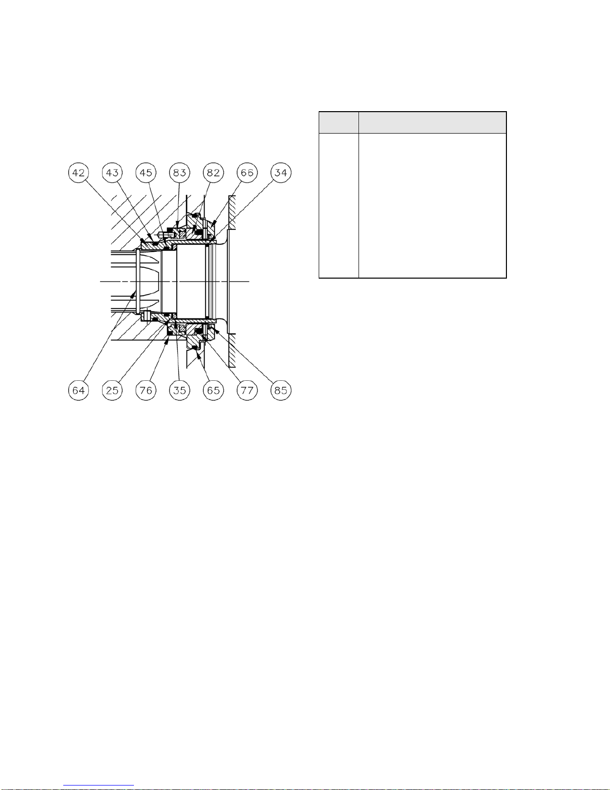
11.1 Single mechanical seal
The seal comprises of a rotary face with
associated 'O' ring which is located in the rotor
with two pins providing the drive. A wave spring
provides a closing force through the static face.
Two pins provide anti-rotation fixing for one
static face with associated static 'O' ring.
ITEM
42
43
45
64
65
66
76
77
82
83
85
11.2 Single mechanical seal removal
1. Remove the gland guards (21).
DESCRIPTION
Shaft Sleeve
‘O’Ring Sleeve/Rotor
‘O’Ring Shaft/Sleeve
Clip Shaft Sleeve Retention
‘O’Ring Seal Housing/Rotorcase
Seal Housing
'O' Ring Mech Seal/Rotor
'O’Ring Mech Seal/Housing
Seal Face Static
Seal Face Rotary
Wave Spring
2 Thoroughly clean the inside and outside
of the seal area on the rotorcase and the
bores of the rotor. The static element of
the seal and the seal housing (66) should
be removed as an assembly.
3. Use a suitably sized screwdriver to lever
between the seal housing and shaft
sleeve (42). This will ease the seal
assembly out of the rotorcase.
4. With the static seal assembly on a suitable
work bench use a screwdriver or lever in
the wave spring recess to prise the static
seal face (82) out of the seal housing.
The wave spring (85) can be pressed
over the drive pins and removed.
5. Use a screwdriver/lever to prise the rotary
seal (83) face out of the rotor.
Page 27

Operatio
n Manual
STP125 Page
25
11.3 Single mechanical seal fitting
1. Ensure the seal housings and seal
recesses are clean.
2. Lightly lubricate the 'O'rings and springs
with a silicon grease (Food quality if required).
3 Position the wave springs (85) into the
seal housing (66).
4. Fit the static face (82) with associated
'O' ring to the seal housing recess.
Ensure location pins engage correctly.
5. Press the rotating faces (83) in to the rotor
bores ensuring the drive pins locate correctly.
6. Position the seal housing loosely in the
rotorcase with the flat inside the rotor
case aligned. Once correctly aligned push
the seal housing into the rotorcase.
Check the seal housing is below the back
face of the rotorcase.
NOTE: To assist fitting the seal housing the rotor and
rotor retaining nut can be used to press the seal
housing.
7. Wipe all lapped seal face surfaces until clean.
8. Follow the rotor assembly procedure in
section 9.8
Page 28
Operatio
n Manual
STP125 Page
26
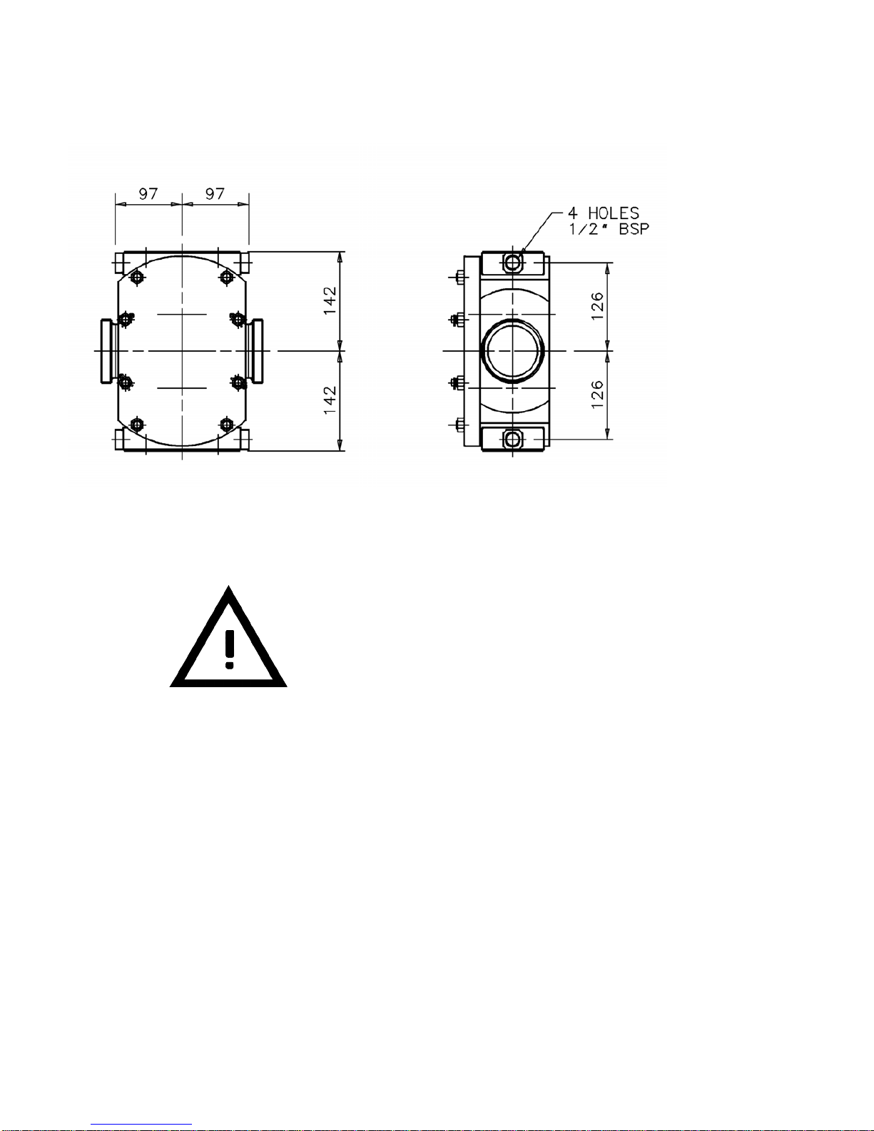
12 Pump heating tank
12.1 Heating tank dimensions
Care should be taken when piping up and
connecting to heating tanks.
Heating tank removal
1. Relieve all pressure from the heating tank
system.
2. Clean heating tank area.
3. Disconnect the pipework.
4. Remove the M8 cap screws and heating
tanks.
Heating tanks supplied with new pumps are
hydrostatically tested. A certificate can be
provided on request.
Prior to operation a hydrostatic test of the
heating system is recommended.
Hydrostatic test pressure (water) :- 90 psi
Maximum working pressure :- 55 psi
Heating tanks should be in operation
approximately 15 minutes prior to pump startup and remain in operation for 15 minutes after
pump shutdown.
12.2 Heating tank fitting
1. Ensure all mating faces are clean and
free of product.
2. Secure using the M8 cap screws and lock
washers. Tighten to a torque of 33 lbft.
3. Connect pipework.
4. Check system for leaks prior to use.
NOTE: If the pump was not originally fitted with
heating tanks, the rotorcase will require drilling
and tapping.
Page 29
Operatio
n Manual
STP125 Page
27
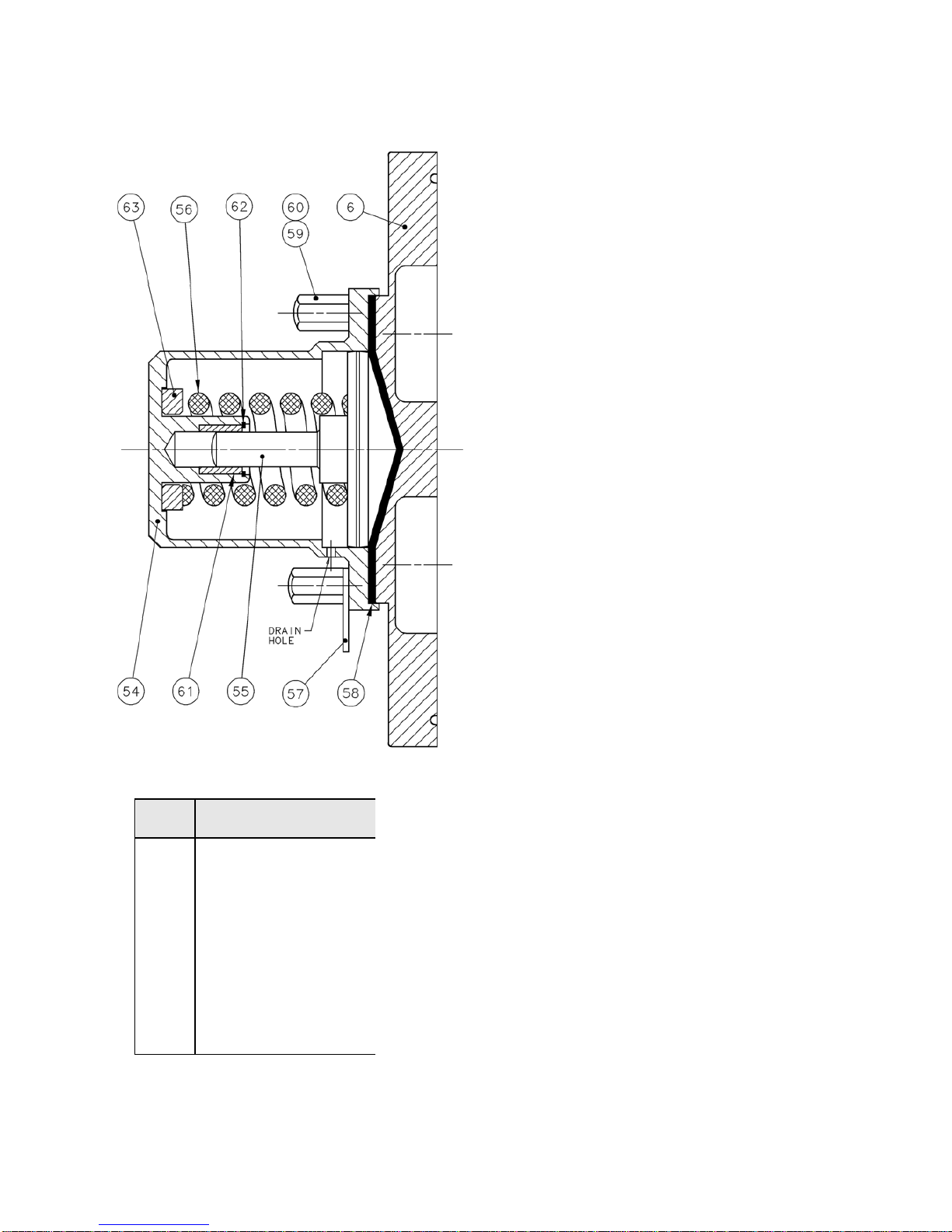
13 Relief Valve
ITEM DESCRIPTION
54
56
55
57
58
60
61
62
63
6
Front Cover
Valve Housing
Spring
Valve Head Stem
Anchor Plate
Diaphragm
Nut
Bush
Circlip
Spacer Valve Preloading
The relief valve is factory set to operate at 145
psi to partially protect the pump from over
pressurisation. The relief pressure can not be
field adjusted.
13.1 Disassembly - Relief valve
Take extreme care when removing the valve
housing as the spring has been compressed.
1. If the pump is still in the system, ensure
there is no pressure in the pump head.
2. Clean the outside of the pump and valve
casing.
3. Remove the nuts (60) and housing (54).
Loosen the nuts equally in order to move
the housing away from the rotorcase
squarely.
4. Remove the valve spring (56), spacer valve
head assembly and diaphragm (58).
13.2 Assembly - Relief valve
1. Ensure mating faces are clean and free
of product.
2. Fit the diaghragm with PTFE face towards
relief valve front cover.
3. Place the spring (56) on the valve head
(55).
4. Fit the valve head/spring assembly into
the valve housing (54).
5. Mount the housing assembly to the front
cover and retain with nuts. Tighten nuts
evenly to a torque of 15 lbft.
Page 30
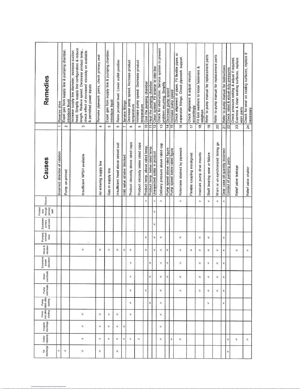
14 Faults, causes and remedies
Page 31

Operatio
n Manual
15 Torque settings/spanner sizes
Pump
STP125 Page
29
Recommended torque settings in lbft
Description
Front cover nut
Rotorcase retainer
Rotor nut
Bearing housing screw
Relief valve nut
Foot screw
Gland guard screw
STP125
30
30
110
33
15
75
15
Tool Sizes
19mm
16mm
41mm
8mm Allen
14mm
8mm Allen
6mm Allen
Page 32
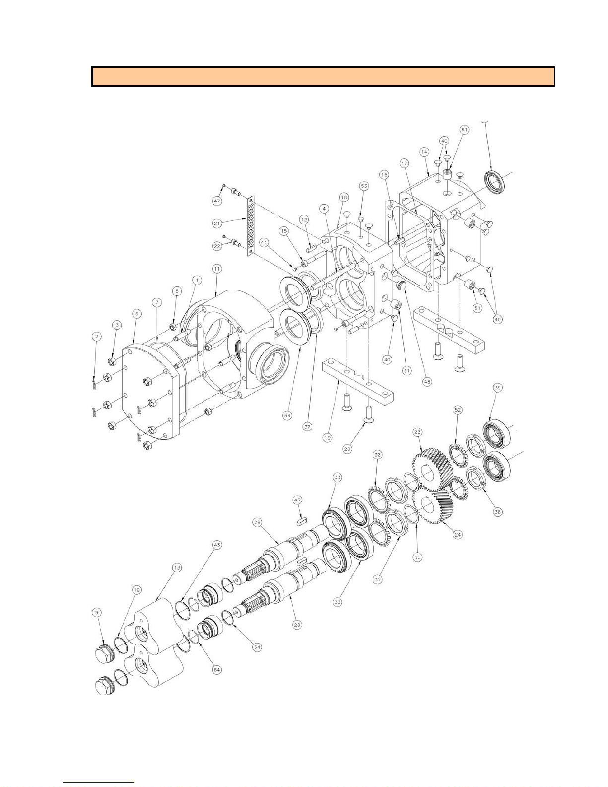
STP125 Pump Model – Exploded View Drawing
STP125 Page
30
16 Exploded view drawing and parts list
41
i
i
i
i
i
i
i
i
i
i
i
.
,....
1
Page 33

STP125 Pump Model
- Main Parts
Dwg.
Item
Description
Qty. Part No.
1
10 bar
503187208
PTFE
522031206
STP125 Page
31
2
3
4
5 NUT ROTORCASE RETENTION - FP2000/STP125 4 518061211
6
7
9 NUT, ROTOR RETENTION - STP125 2 518061212
10
11
12 DOWEL - M10 - FP2000/STP125 2 199101200
13
14 HOUSING GEAR ALUM - STP125 1 528030205
15 CAPSCREW HEX HD ISO 8.8 M10x70mm 316 S.S 4 128010070
16 DOWEL - M10 - FP2000/STP125 2 199101200
17 GASKET GEAR/BRG HOUSING - FP2000/STP125 1 526151201
18 BEARING HSNG., LIQ. PUMP, ALUM - STP125 1 502030202
19 FOOT, GEARCASE, HORIZ. PORT, SS - STP125 2 507034204
20 CAPSCREW, COUNTERSUNK, M10x25mm - STP125 4 124106224
21 GUARD GLAND - FP2000/STP125 2 521143202
22 SOCKET HD CAPSCREW- M8x16mm- 316 STAINLS 4 126008216
23 TIMING GEAR SET - FP2000 / STP125 1 529000208
24 TIMING GEAR SET - FP2000 / STP125 1 529000208
28 SHAFT, DRIVEN - STP125 1 504033215
29 SHAFT, DRIVE, HYDRAULIC - STP125 1 504033214
30 SHIM KIT STEEL - FP2000/STP125 1 set 516072229
31 NUT BEARING LARGE - FP2000/STP125 2 518060219
32 WASHER TAB BEARING - FP2000/STP125 2 518020208
33 BEARING - TAPER ROLLER - FP2000/STP125 4 510001202
34 SLINGER SEAL RETAINER - STP125 NBR 2 518080203
36 RETAINER, SEAL - STP125 2 518081210
37 SEAL, LIP, GLAND END - STP125 2 512010220
38 NUT BEARING SMALL - FP2000/STP125 2 518060220
39 BEARING, ROLLER, REAR - STP125 2 510003205
40 BLANKING PLUG, PLASTIC, LARGE - STP125 14 521214210
41 SEAL, LIP (REAR), NITRILE - STP125 1 512010219
43
STUD 12MM x 54 WITH CLIPHOLE
RETAINER SS PUMP CASE NUT 'R' CLIP
NUT HEX FULL S/S M12
STUD - M12 X 155MM S/S - FP2000/STP125
COVER, FLAT FRONT, NO RLF. VLV. - STP125
O-RING SS PUMP FRONT COVER -266
O-RING, ROTOR, STP125, RTR NUT END
BODY, LIQ. PUMP, SS, 3" ACME - STP125
BODY, SS, 3" ACME - STP125, FOR HT. TANK
ROTOR, TRILOBE, O-RING - STP125
ROTOR, TRILOBE, MECH. SL. - STP125
O-RING, ROTOR, STP125, O-RING/LIP
O-RING, ROTOR, STP125, RTR NUT END
NBR
Viton
PTFE
NBR
Viton
PTFE
7 bar
10 bar
5 bar
NBR
Viton
PTFE
NBR
Viton
4 170412250
4 518101200
8 190012200
4 199121200
1 521042214
1
2
1
2
2
522000205
522010206
522031200
522001250
522011241
522031206
500030208
500030209
503187206
503187205
503187207
522001246
522011242
522031207
522001250
522011241
44 PLUG, GEAR HSNG SCREW, PLASTIC - STP125 4 521214211
46 KEY -GEAR 3/8 SQ X 1-1/4" -FP2000/STP125 2 299014218
47 PLUG, GLAND GUARD SCREW,PLASTIC - STP125 4 521214212
48 HYD SIGHTGLASS w/WASHER FOR SS PUMP -UK 2 307058203
51 PLUG TAPER BSPT 1/2X3/4 - FP2000/STP125 6 248108508
52 WASHER TAB GEAR - FP2000/STP125 2 518020206
53 BLANKING PLUG, PLASTIC, SMALL - STP125 3 521214213
64 CLIP, SHAFT SLEEVE RETAINER – STP125 2 518081203
Page 34
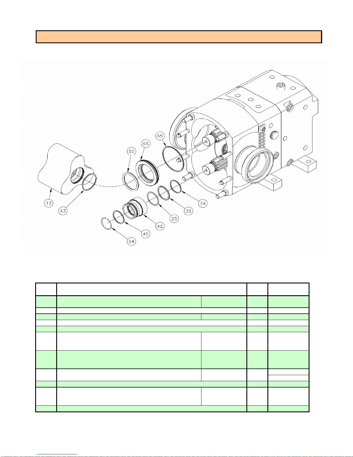
O-Ring
Seal
Parts
-
STP125
Pump
Model
Dwg.
Item
7 bar
10 bar
503187206
503187205
2
STP125 Page
32
13 ROTOR, TRILOBE, O-RING - STP125
25 SHIM SET, ROTOR ALIGN, S/S - STP125 1 set 516073207
34 SLINGER SEAL RETAINER - STP125 NBR 2 518080203
35 SETTING RING - STP125 2 518081209
42 SEAL SLEEVE, O-RING VERSION - STP125 2 516041214
43 O-RING, ROTOR, STP125
45 O-RING, SHAFT, STP125
50 O-RING, SEAL, STP125
64 CLIP, SHAFT SLEEVE RETAINER - STP125 2 518081203
65 O-RING, HOUSING, STP125
66 SEAL HOUSING - STP125 (O-RING SEALS)
Description
NBR
Viton
PTFE
NBR
Viton
PTFE
NBR
Viton
NBR
Viton
PTFE
Qty.
2
2
2
2
2
Part No.
522001246
522011242
522031207
522001247
522011243
522031208
522001249
522011244
522001248
522011245
522031209
518081204
Page 35
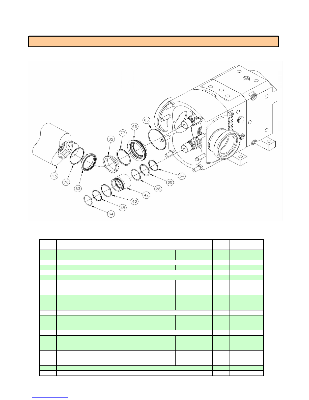
Dwg.
Item
5 bar
10 bar
503187207
503187208
25 SHIM SET, ROTOR
ALIGN,
S/S - STP125
1
set 516073207
34
SLINGER
SEAL
RETAINER
-
STP125
NBR 2 518080203
35
SETTING
RING - STP125
2
518081209
42
SEAL
SLEEVE,
MECH.
SEAL
VERSION
-
STP125
2
516041216
NBR
522001250
NBR
522001247
64 CLIP, SHAFT
SLEEVE
RETAINER
-
STP125
2
518081203
NBR
522001248
66 SEAL
HOUSING
-
STP125
(MECHANICAL
SEALS)
2
518081206
NBR
522001251
NBR
522001252
82 STATIONARY
SEAL
RING,
SS -
STP125
2
518081207
518081208
STP125 Page
33
Mechanical Seal Parts - STP125 Pump Model
13
ROTOR, TRILOBE, MECH. SL. - STP125
43
O-RING, ROTOR, STP125, RTR NUT END
45
O-RING, SHAFT, STP125
65
O-RING, HOUSING, STP125
76
ROTARY SEAL RING, STP125, MECH.
77
STATIONARY SEAL RING, STP125, MECH.
Description
Viton
PTFE
Viton
PTFE
Viton
PTFE
Viton
PTFE
Viton
PTFE
Qty. Part No.
2
2
522011241
522031206
2
522011243
522031208
2
522011245
522031209
2
522011246
522031210
2
522011247
522031211
83
ROTARY SEAL ASS'Y - STP125 (MECH. SEALS)
2
Page 36
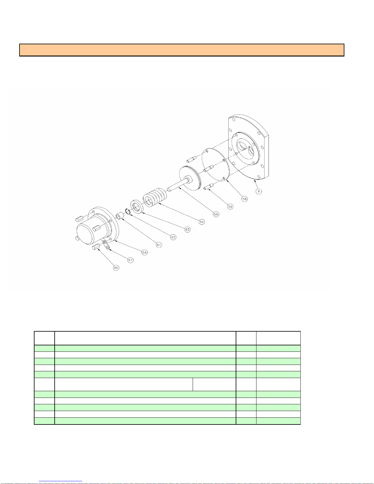
STP125 Page
34
Relief Valve Parts - STP125 Pump Model
Dwg.
Item
6
COVER, FLAT FRONT,FOR REL. VLV. -
54
BODY RELIEF VLV FP2000/STP125 INT.
55
RELIEF VALVE HEAD/STEM -
56
SPRING COMP 65 PSI RELIEF
57
ANCHOR PLATE, SS, FOR RELIEF VLV
58
SEAL DIAPHRAGM,
59
STUD, M10-1.5 x 40MM LG., S/S -
60
NUT, HEX, HOUSING STUD - M10 X 38MM,
61
BUSHING PLAIN 2130-MT POPPET
62
RETAINING RING INT. S/S 0.917x0.026
63
SPACER SPRING, RV, SS, 10 BAR -
Description
STP125
VALVE
FP2000/STP125
STP125
STP125
SUPP.
-STP125
VALVE
GRVE
STP125
PTFE/NBR
PTFE/Viton
S/S
Qty.
1
1
1
1
1
1
4
4
1
1
1
Part
No.
521042215
500074202
532051202
517022201
532120201
513132200
513132201
168210240
188410238
510102206
244014201
516041217
Page 37
STP125 Page
35
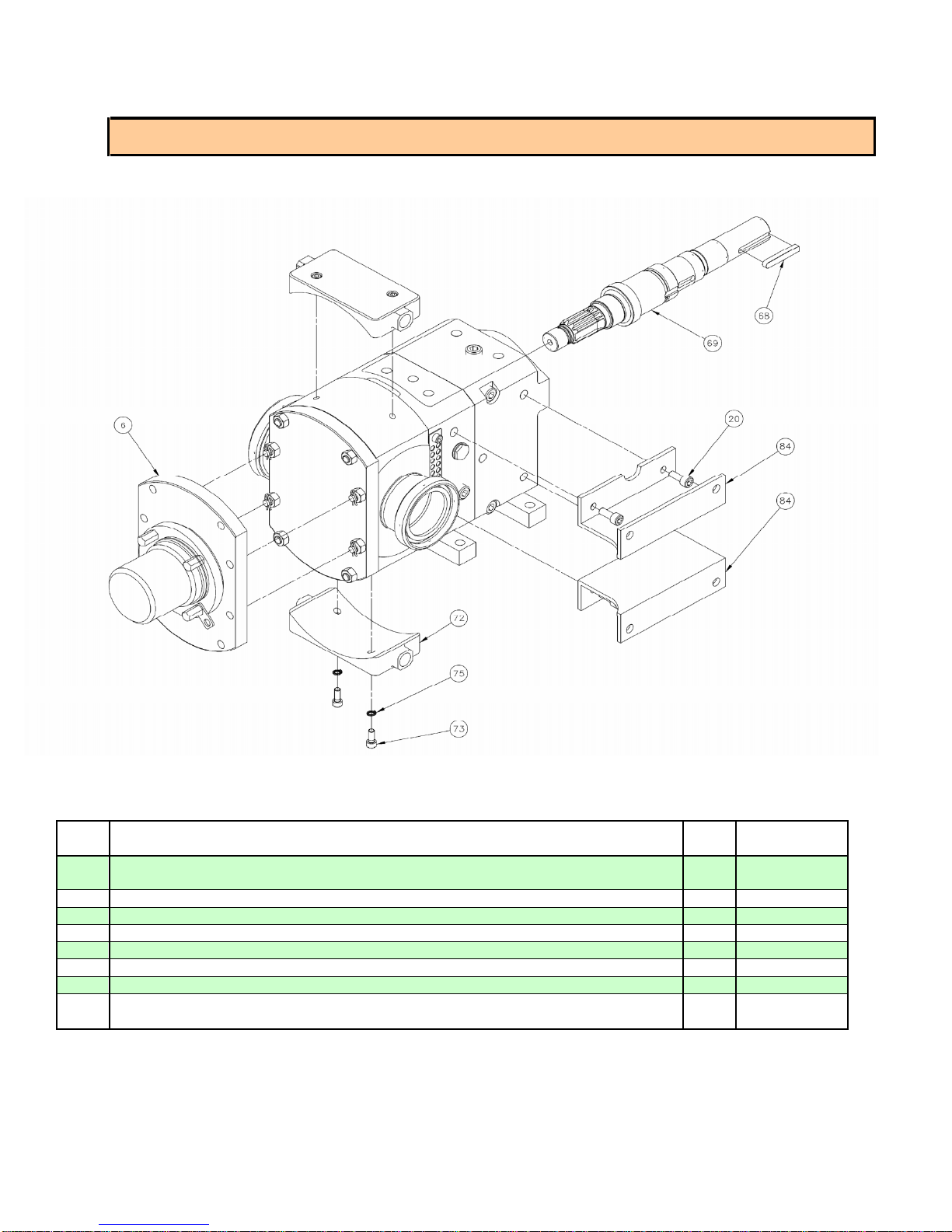
Other Optional Parts - STP125 Pump Model
Dwg.
Item
COVER ASS'Y., COMP. w/RV, NBR -
6
COVER ASS'Y., COMP. w/RV, VITON -
20
CAPSCREW SKT HD ISO 8.8 M12 x 30mm
68
KEY RND END 10MM X 8MM X
69
SHAFT, DRIVE, KEYED -
72
HEATING TANK FOR ROTORCASE, SS -
73
CAPSCREW SKT HD M8 X 20MM S/S
75
WASHER LOCK SST M8
FOOT, GEARCASE, VERT. PORT, LH -
84
FOOT, GEARCASE, VERT. PORT, RH -
63MM
STP125
STP125
STP125
GRA4-70
Description
PLTD.
STP125
STP125
STP125
Qty.
1
4
1
1
2
4
4
1
1
Part
No.
521042216
521042217
130112030
199050209
504033216
500030210
126108220
194008200
507034205
507034206
Page 38
7 bar
503187206
DOUBLE
LIP SEAL,
ROTORCASE
-
STP125
PTFE
2
512141200
STP125 Page
36
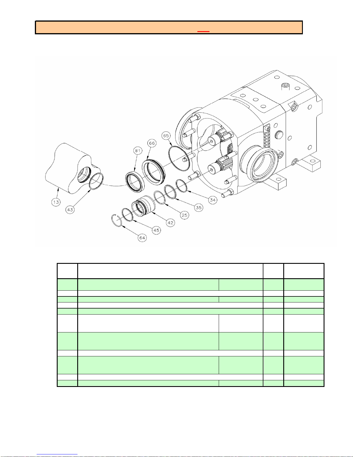
Lip Seal Parts - STP125 Pump Model (not 3A compliant)
Dwg.
Item
13
ROTOR, TRILOBE, O-RING -
25
SHIM SET, ROTOR ALIGN, S/S -
34
SLINGER SEAL RETAINER -
35
SETTING RING -
42
SEAL SLEEVE, LIP SEAL VERSION -
43
O-RING, ROTOR,
45
O-RING, SHAFT,
64
CLIP, SHAFT SLEEVE RETAINER -
65
O-RING, HOUSING,
66
SEAL HOUSING - STP125 (LIP
81
STP125
STP125
STP125
STP125
STP125
STP125
STP125
SEALS)
Description
1
STP125
STP125
10
bar
NBR
NBR
Viton
PTFE
NBR
Viton
PTFE
NBR
Viton
PTFE
Qty.
2
set
2
2
2
2
2
2
2
2
Part
No.
503187205
516073207
518080203
518081209
516041215
522001246
522011242
522031207
522001247
522011243
522031208
518081203
522001248
522011245
522031209
518081205
Page 39

Page 40

For additional information, contact your local representative or visit:
www.contactgd.com/compressors
©2015 Gardner Denver, Inc. Printed in U.S.A.
 Loading...