

Page 1
OPERATION,
MAINTENANCE
and
INSTALLATION
MANUAL
40 G.P.M.
3500 P.S.I.
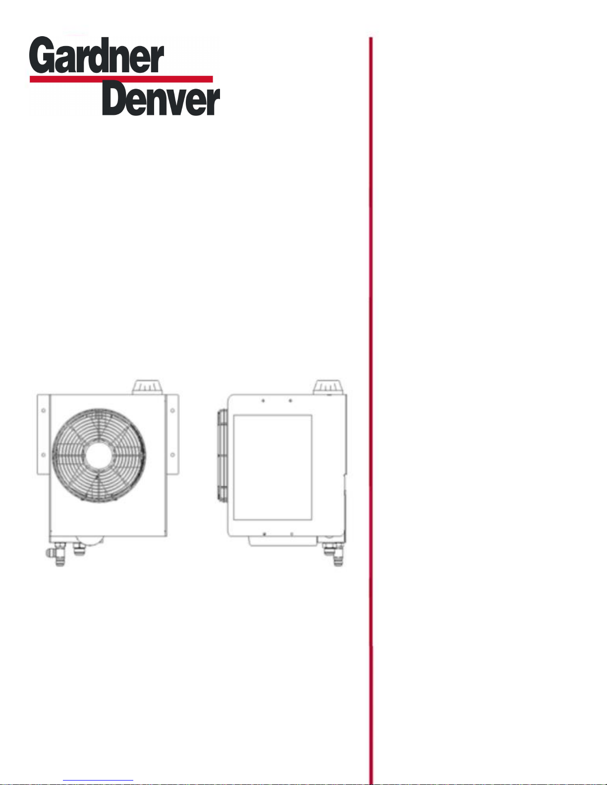
MH3 HYDRAPAK
February 3, 2015
999042002
VERSION: 03
Page 2

Page 3

SAFETY
Do not work under the vehicle when the engine is
running. Do not work on hydraulic system when the engine
is running. Do not go near leaks when engine is running.
• high pressure oil easily punctures skin causing serious
injury, gangrene or death.
•
• if injured, seek emergency medical help.
• Immediate surgery is required to remove oil.
• do not use finger or skin to check for leaks.
• lower load or relieve hydraulic pressure before
loosening fittings.
A serious or fatal injury can occur . . .
• if you lack proper training.
• if you fail to follow proper procedures.
• if you do not use proper tools and safety equipment.
• if you assemble components improperly.
• if you use incompatible components.
• if you use worn-out or damaged
components. Read, understand and follow
this manual.
• Get proper training.
• Learn and follow safe operating procedures.
• Use proper tools and safety equipment.
• Use proper components in good condition.
INITIAL HYD. SYS. START UP : (2 people
1. Hydraulic oil: Non-foaming. We recommend Shell
Tellus “T” series ISO 32 or equivalent.
2. Fill the Hydrapak with the above listed hydraulic oil.
Use a paint filter as a strainer while filling.
3. After Hydrapak is filled, check for hydraulic system
leaks.
4. Slowly raise the clutch while the engine is running to
engage the P.T.O. and pump. Stop when level
drops in the Hydrapak tank to just below the dip
stick.
5. Disengage the P.T.O. (press clutch all the way in)
Re-fill Hydrapak and repeat step 4 until oil level in tank
does not drop while the P.T.O. is engaged.
PRECAUTIONS:
required)
MAINTENANCE:
1. Change hydraulic oil filter every 6 months*
2. Change hydraulic oil every 6 months*
3. Check oil level each week. Check with system
off. (should be between the marks on the dip
stick)
4. Visually check the system each week - all fittings,
hoses and Hydrapak mounting.
5. Grease PTO / Pump spline every 3 months ( grease
every month for high duty cycle applications)
* An oil analysis program is
recommended.
NORMAL
OPERATION:
VISUAL CHECKS BEFORE STARTING SYSTEM:
1. Check that the oil level is between the marks
on the dipstick.
2. Remove any obstructions from radiator and fan.
STARTING SYSTEM:
1. Ensure brake is applied.
2. Ensure control valves are in neutral position.
3. Engage PTO per manufacturers instructions.
4. Oil level may drop if air is trapped in
system. Stop the system and top off tank if
necessary.
5. Operate the valving slowly
6. To stop the system, follow steps in reverse.
Page 4

POWER TAKE OFF & HYDRAULIC
1. Mount power take off,and brace hydraulic pump per manufacturers instructions.
2. Ensure that the female spline of power take off is filled with grease.
PUMP:
3. Mount hydraulic pump to P.T.O. using only capscrews provided.
Note : To avoid premature spline wear of the pump and PTO from
manufacturer
for the correct engine speed (based on
application)
torsional vibration consult
that will reduce
torsional vibration.
the
engine
SUCTION LINE INSTALLATION GUIDELINES:
Special attention should be given to applications utilizing a double suction or large diameter piping. When
excessive loading or insufficient support of the suction piping exists, reservoir fatigue fractures, loss of oil,
and decreased hose life are likely to occur.
1. For double suction applications, is the weight and length of pipe work (fittings) is excessive? If so,
shorten the piping to reduce vibration and add support brackets to compensate for the added weight.
Additional support brackets should be attached to a common point with the Hyrdrapak so that flexing
of the truck frame and vibration does not induce additional stress on the Hydrapak.
2 On direct coupled double suction piping, if mounting conditions do not accommodate additional
support brackets, consider line mounting a pipe "Y" to fill the need for a double suction. When line
mounting the "Y", a single section of large diameter hose can be fitted to the reservoir suction fitting
leading into the "Y" downstream. Appropriately sized piping can then exit the "Y" and lead into the
pump inlet sections. Always make sure the "Y" pipe is supported and consideration is given to the
remaining points.
MOUNTING
HYDRAPAK:
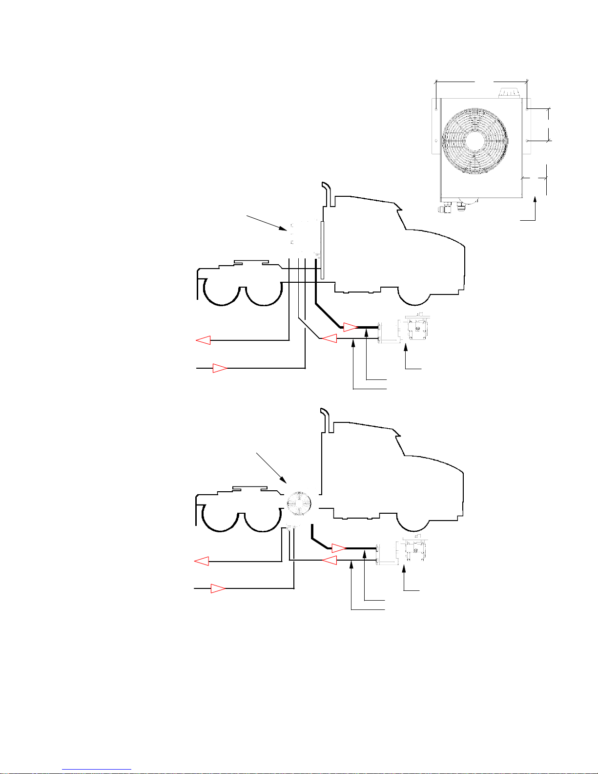
Behind the cab is the preferred mounting method.
Frame rail mount is the secondary choice.
1. Drill 7/16” dia. holes as shown in Fig.1. Use the capscrews, washers and nuts supplied to mount the Hydrapak.
2. Be sure to allow 4” of space between radiator and any solid obstruction that will effect air flow into radiator.
3. Radiator must be shielded from rocks and road debris.
HYDRAULIC HOSES &
1. Do not use thread tape or pipe dope as this will contaminate the hydraulic system.
2. All hoses are customer supplied. Fit all hoses as per separate system drawings provided by Drum.
3. All high pressure hoses must have a working pressure rating equal to or higher than the hydraulic system relief valve
setting.
4. The suction hose must be suitable for 28”Hg vacuum service.
5. Hoses must have proper support near the Hydrapak to reduce loading from hose and fluid weight.
Unsupported hoses pull on the welded connection fittings of the reservoir and may result in reservoir
stress fractures and shortened hose life.
6. Proper installation of the hoses should include a slight bend in the hoses near the connections. This
allows them to flex, reduce vibration stress and hose shrinkage under load.
7. All hoses should use the largest bend radius possible to reduce pressure drop and loading. Always
follow the hose manufacturer's recommendations for hose duty and bend radius. If an excessively
tight bend is required, consider using a section of rigid pipe such as a street 90 with increased pipe
diameter.
FITTINGS:
Page 5
4”
16.0”
5.50”
BEHIND THE
MOUNT
CAB
Suction hose sizing
0 to 19 gpm hyd. flow use 1-1/4”
20 to 25 gpm hyd. flow use 1-1/2”
26 to 40 gpm hyd. flow use 2”
chart
IDEAL SUCTION
behind cab on fabricated
mounting bracket
suction hose
suction hose
suction hose
CONDITION
EXAMPLE
Refer to specific system
schematic for details on
your system
ONL
Y.
open space required
Fig. 1
Low pressure return from hydraulic
FRAME RAIL MOUNT
Note: for severe duty off
applications
Hydrapak
rail.
Use # 507044228 bracket
mount Hydrapak to
Consult factory for
directly
hydraulic motor and valving
do not
High pressure to
motor and valving
Note: 4” of space (shown above)
Radiator must be shielded from
road
mount
to the
frame
to
frame.
assistance.
must be maintained between
radiator and any obstructions.
rocks and road debris.
suction hose see
High pressure from hydraulic pump to Hydrapak
Power take off & hydraulic pump
EXAMPLE
Refer to specific system
schematic for details on
your system
ONLY.
chart
hydraulic motor and valving
High pressure to
Low pressure return from hydraulic
Note: See
specific
motor and valving
system
circuit
drawing for complete
hydraulic plumbing information
Power take off & hydraulic pump
suction hose see
High pressure from hydraulic pump to Hydrapak
chart
Page 6
TRAILER MOUNTED
HYDRAPAK
SUCTION HOSE SIZING
0 to 15 gpm hyd. flow use 1-1/4”
15 to 23 gpm hyd. flow use 1-1/2”
23 to 40 gpm hyd. flow use 2”
This hose sizing chart is based on
of 15 feet. For
The
bottom of the Hydrapak
The maximum
pumps.Consult
To hydraulic
pump inlet
To hydraulic
pump inlet
To hydraulic
pump inlet
routing
of the
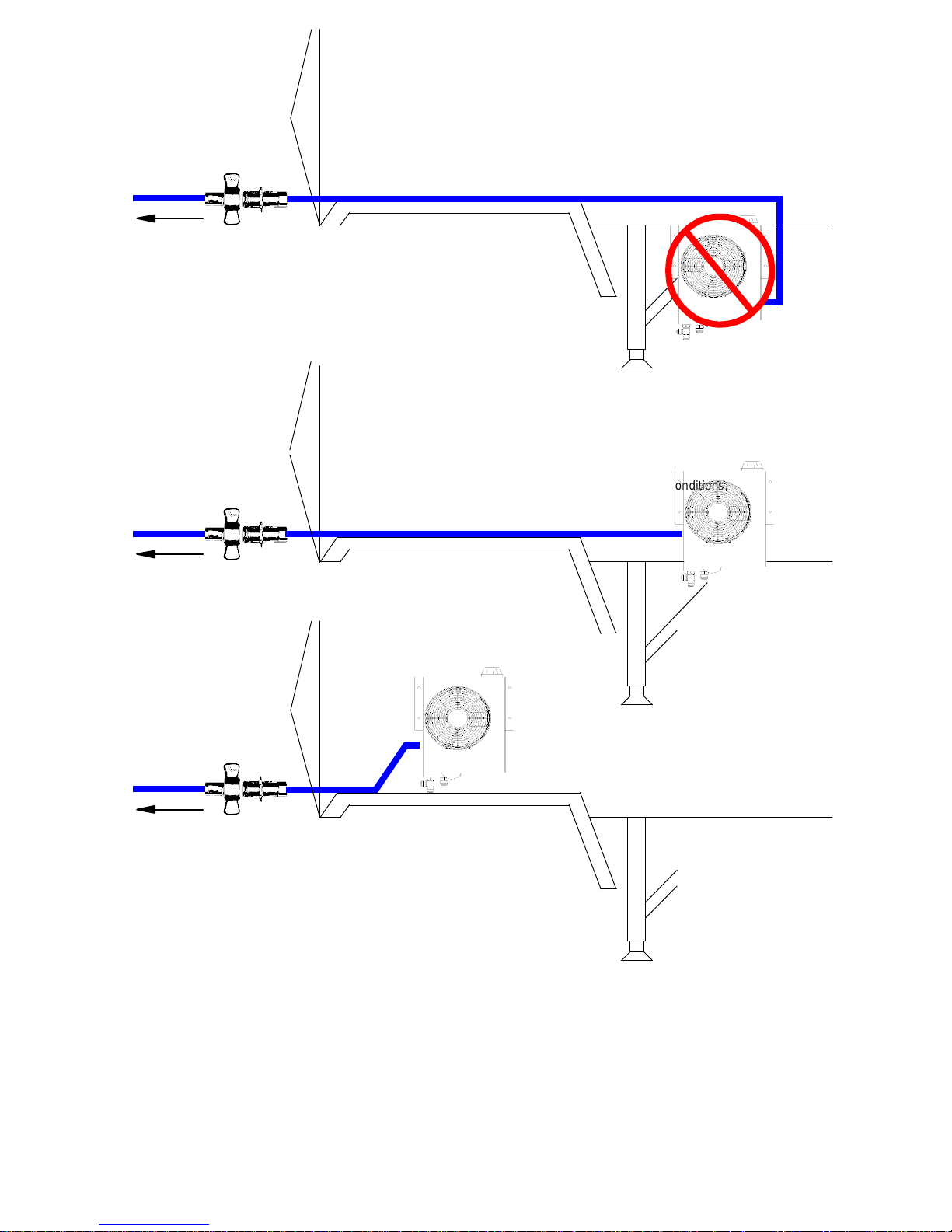
Detail 3 is the best possible mounting configuration.
The mounting of the Hydrapak as shown will help to improve the suction
conditions.
This type of Hydrapak mounting will provide good system performance
provided that there are no rises in the suction line above the Hydrapak
reservior.
Note: pressure drop calculations must be performed on the specific system
and corresponding tractor unit to insure acceptable suction conditions.
Consult factory for
CHART:
suction
recommended
lines that have an over-all length that is more than 15 feet Consult the factory for
suction
reservior
the factory for
Detail 1 is the worst possible suction condition.
This mounting may cause severe hydraulic pump cavitation which will
reduce the hydraulic pump life.
The hydraulic system as shown in this mounting configuration will
operate very poorly or not at all.
DETAIL1
Detail 2 is a possible choice for hydraulic mounting.
The straight line run on the suction line is acceptable.
Caution must be taken with the routing of the suction line to insure that
there are no rises in the suction line that are above the Hydrapak oil
reservior.
Note: pressure drop calculations must be performed on the specific
system
and corresponding tractor unit to insure acceptable suction c
Consult factory for
DETAIL 2
DETAIL 3
application assistance.
suction
suction
line must be done to avoid excessive pressure drop. Elbows
vacuum at the
assistance
line on trailer and
suction
will cause excessive pressure drop in the
line on trailer and
line on trailer and
mounting
the Hydrapak as shown in
hydraulic
application assistance.
tractor.
tractor.
tractor.
“detail
pump inlet is 5” Hg for gear pumps and 2”Hg for
3”and having an over-all
suction line.
onditions.
,reducers,and
suction
assistance.
line rises above
piston
line
length
the
Page 7

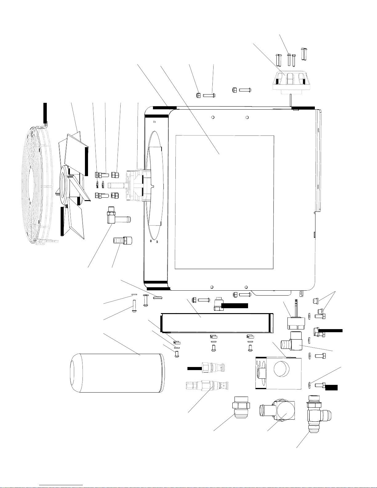
ITEM DESCRIPTION PART NO. QTY.
1
1
1 MAINFRAME
50008021
8 1 2” NPTF
SUCTION
2
HYDRAULIC
FAN
MOTOR
300001228
1 3 GROMMET
521070206
1 4 HOSE
ASSY.
FAN
TO
MANIFOLD
407021216
1
NOT
SHOWN
5
HYD.
RADIATOR
308011209
1 6 RADIATOR
BLANKING
PLATE
540063209
1 7 RADIATOR
BY-
PASS
CHECK
304059203
1 8 HYD.RELIEF
VALVE
303000208
1
2500
PSI 8 HYD.RELIEF
VALVE
303000210
1
3000
PSI 9 HYDRAULIC
PLUG
SOCKET
HEAD
302123206
2 # 4
ORBM
10
HYDRAULIC
PLUG
SOCKET
HEAD
302123200
1 # 8
ORBM
11 HYDRAULI
C MANIFOLD
311003202
1 12 # 10-32
GR.5
PLATED
NUT
236103000
1 13 MANIFOLD
CHECK
VALVE
DISC
532111202
1
NOT
SHOWN
14 MANIFOLD
CHECK
VALVE
SPRING
517000204
1 NOT SHOWN
15 MANIFOLD
CHECK
VALVE
WASHER
532112200
1 NOT SHOWN
16 MANIFOLD
CHECK
VALV
GUIDE
BOLT
212103040
1 NOT SHOWN
17 FAN
50602220
6 1
18
RETAININ
G RING FOR FAN
244010200
2 19
FAN
MOTOR
FLOW
CONTROL
304060209
1 20
HYDRAULI
C FITTING
302065207
1 # 16
ORBM
X # 16
JICM
21
HYDRAULIC
TEE FITTING
302005200
1 # 12 JICM
X # 12
ORBM
X # 12
JICM
22 FILLER
/
BREATHER
CAP
30900120
2 1
23 FAN
GRILL
/
GUARD
521022201
1 24 MAGNETIC
DRAIN
PLUG
258208208
1 # 8
NPTM
25
HYDRAULIC
FILTER
306000206
1
SPIN
ON
STYLE
26
CAP
SCREW
75A10Z
4
5/16-18 X 1 GR5
PLATED
27
NYLOCK
NUT
236105400
4
5/16-18 PLATED
28
LOCK
WASHER
405757
4
5/16 GR 5 S.S. 29 LOCK
WSHER
240004400
3
1/4 GR 5 PLATED
30
FLAT
WAHER
240404000
4
1/4 GR 5 PLATED
31
NYLOCK
NUT
299123200
4
1/4-20 GR 5 PLATED
32 HYDRULI
C ELBO
W FITTING
302095219
1 # 6
ORBM
X # 4
JICM
33 HOSE
CLAMP
WORM
TYPE
299070211
2 NOT SHOWN
34
HOSE
CLAMP
SLOTLESS
WORM
299070207
5
NOT
SHOWN
35
HOSE
CLAMP
CONSTANT
TENSION
29907021
6 2 NOT
SHOWN
36
HYDRAULIC
ELBOW
FITTING
302183203
1 # 16 HOSE
BARB
X # 20
ORBM
37
HYDRAULIC
FITTING
302170205
1 # 8
HOSE
BARB
X # 6
NPTM
38 HYDRAULI
C HOSE
310010208
1
1/2” FAN MTR
. RETUR
N NOT
SHOWN
39 HYDRAULI
C HOSE
310030211
1 1” MANIFOL
D TO
RADIATO
R NOT
SHOWN
40
HYDRAULIC
HOSE
310030212
1 1” RADIATOR
TO TANK
NOTSHOWN
41
HYDRAULIC
ELBOW
FITTING
302183202
1 # 8
HOSE
BARB
X # 6
ORBM
42
HYDRAULIC
ELBOW
FITTING
302180204
1 # 12 HOSE
BARB
X # 12
MPTM
43
SPEE
D NUTS
299120204
3
1/4-20 44 CAP
SCREW
214004216
2
1/4-20 X 1 S.S. HEX
HEAD
45
CAP
SCREW
214304
212 7 1/4-20 X 3/4
S.S. BTN HEAD
47
CAP
SCREW
212303216
6 # 10-32 X 1
S.S. BTN
HEAD
48
HYDRAULIC
HOSE
310030217
1
RADIATOR
CHECK
TO
TANK
NOT
SHOWN
49
CAP SCREW
405766
4
5/16-1/8 X 7/8 S.S.
50
SIGHT GLASS
307058205
1
NOT
SHOWN
51
RIVET
299061200
2
NOT SHOWN
52
FOAM RUBBER
015001200
38
NOT SHOWN
PARTS LIST
MAINFRAME
500080217
1-1/2 CODE 61 SUCTION
Page 8

Hydrapak Optional Equipment
409030201 HYD TEST POINT PLUG ASSY 5000psiw/ADP
703000210 KIT PRESSURE CAP OPTION MH SERIES
717000200 HEATER KIT HYDRAPAK TANK 12 vdc MOBILE
717001200 HEATER KIT HYDRAPAK TANK 12 vac STATIC
309072200 HYD FLLR CAP THREADED (NON-VENTED)
303011200 HYD RELIEF VALVE 65 PSI 1” NPTF
309001203 HYD FILLER/BREATHER CAP LOCKIN
MH3 HYDRAPAK
Page 9
47 (6)
22
1
5
31 (4) 45 (7)
23
17
18
26 (8)
27 (4)
2
25
3
43 (3)
29 (3)
6
45 (7)
24
11
9
7
10
42
41 37
29 (2)
44 (2)
19
8
20
36
21
28 (8)
26
REF
Page 10

WARRANTY
WARRANTY: The Seller warrants the goods sold hereunder against defects in workmanship or materials under normal and proper installation for a period
of twelve (12) months from the date of delivery. BUYER’S SOLE AND EXCLUSIVE REMEDY UNDER THIS WARRANTY IS FOR THE REPAIR OR
REPLACEMENT AT SELLER’S OPTION, WITHOUT CHARGE TO BUYER EXCEPT FOR SHIPPING EXPENSES, AT THE OFFICE OF THE SELLER IN
LOUISVILLE, KENTUCKY, OF ANY PART WHICH HAS PROVEN TO BE DEFECTIVE AT THE TIME IT WAS DELIVERED. ANY GOODS UNDER
WARRANTY MUST BE RETURNED TO THE SELLER’S OFFICE FOR INSPECTION BY THE SELLER AND, IF ANY SUCH GOODS ARE FOUND TO BE
DEFECTIVE, FOR REPAIR OR REPLACEMENT. ALL FREIGHT AND EXPENSES OF SHIPMENT TO AND FROM THE SELLER’S OFFICE SHALL BE
BORNE BY THE BUYER. THE SELLER IS NOT RESPONSIBLE FOR ANY EXPENSES OF ANY NATURE INCURRED FOR ANY REPAIRS TO
ALTERATIONS MADE BY OTHERS TO THE GOODS OR ANY OTHER EQUIPMENT WITHOUT THE PREVIOUS WRITTEN CONSENT OF THE SELLER.
SHOULD THE GOODS BE PARTIALLY OR FULLY INSTALLED, ALTERED, STRIPPED, REPAIRED, SERVICED, OR MAINTAINED BY ANY PERSON
OTHER THAN AUTHORIZED AGENTS AND EMPLOYEES OF THE SELLER, WITHOUT THE PREVIOUS CONSENT OF THE SELLER, OR MISUSED IN
ANY WAY, THIS WARRANTY SHALL BE VOID. THIS WARRANTY CONSTITUTES THE ONLY WARRANTY BY THE SELLER OF THE GOODS AND IS
IN LIEU OF ALL OTHER WARRANTIES, EXPRESS OR IMPLIED, INCLUDING, BUT NOT LIMITED TO, WARRANTIES OF MERCHANTABILITY OR
WARRANTIES OF FITNESS FOR A PARTICULAR PURPOSE. IN NO EVENT SHALL SELLER BE LIABLE FOR BUYER’S ATTORNEY’S FEES.
NO CONSEQUENTIAL DAMAGES: UNDER NO CIRCUMSTANCES SHALL THE SELLER BE LIABLE FOR (A) ANY DAMAGE, INJURY, BREAKAGE OR
LOSS OF ANY KIND WHATSOEVER, (B) ANY LOSS OF INCOME, OR (C) ANY CONSEQUENTIAL LOSS.
NO TORT LIABILITY: SELLER DISCLAIMS ANY LIABILITY FOR CLAIMS BASED ON SELLER’S NEGLIGENCE OR STRICT LIABILITY IN TORT.
PARTS: This Warranty and all disclaimers and limitations of liability shall apply to all parts sold to Buyer.
TRAINING AND SUPERVISION: The buyer hereby assumes the affirmative duty to properly educate, instruct and supervise its employees and all others,
except employees of the Seller, in the safe, proper use and operation of the goods. The Buyer agrees to indemnify the Seller for any damages paid by the
latter as a result of the Buyer’s failure to perform this affirmative duty.
The goods are not designed or intended for use with every substance. If the material which the Buyer contemplates transferring with the goods has corrosive
or polymerizing or other properties which may result in unsatisfactory or dangerous operations, the Seller has no liability or responsibility for performance of
the goods.
RETURN OF GOODS: No goods supplied may be returned to the Seller for credit without the Seller’s prior written authorization before transportation thereof
commences and in such cases transportation must be prepaid and the Buyer’s name, address, original order number and the Seller’s invoice number must
be clearly marked on the shipping tag.
If any goods are returned to the Seller for repair or under warranty and no instructions are received within two months after Seller receives the goods for repair
or sends notice to Buyer of the disallowance of a warranty claim, the Seller reserves the right to scrap the goods returned, and no subsequent claim for any
costs or losses will be accepted.
APPLICABLE LAW AND VENUE: The rights and obligations of the parties hereunder shall be governed in all respects, including all questions of construction
and performance of this order, by the laws of Kentucky. All disputes concerning this order shall be resolved in an appropriate state or federal court located
in Louisville, Kentucky.
MODIFICATION OR RESCISSION: This warranty can only be modified or rescinded by a written agreement signed by an officer of both the Buyer and the
Seller.
For additional information, contact your local representative or visit:
www.contactgd.com/compressors
©2015 Gardner Denver, Inc. Printed in U.S.A.
Part #
999042002
Revision 03
February 3, 2015
 Loading...