


GARDNER DENVER
DUPLEX POWER PUMP
MODELS:
FXF – 5”
FXG – 6”
FXX – 8”
3–600
6th Edition
June, 1997
FXD – 10”
FXE – 10”
OPERATING AND
SERVICE MANUAL

MAINT AIN PUMP RELIABILITY AND PERFORMANCE WITH
GENUINE GARDNER DENVER
P ARTS AND SUPPORT SERVICES
Gardner Denver
manufactured to original tolerances and designed for
optimum dependability. Design and material innovations are the result of years of experience with
hundreds of different pump applications. Reliability in
materials and quality assurance are incorporated in our
genuine replacement parts.
and OPI genuine pump parts are
gency parts by direct access to the Gardner Denver
Machinery Inc. Master Distribution Center (MDC) in
Memphis, Tennessee.
Your authorized distributor can support your Gardner
Denver and OPI pump needs with these services:
1. Trained parts specialists to assist you in selecting the correct replacement parts.
Your authorized Gardner Denver and OPI distributor offers all the backup you’ll need. A worldwide
network of authorized distributors provides the finest
product support in the pump industry.
2. Repair and maintenance kits designed with the
necessary parts to simplify servicing your pump.
Authorized distributor service technicians are factory–
trained and skilled in pump maintenance and repair.
Your local authorized distributor maintains a large inventory of genuine parts and he is backed up for emer-
They are ready to respond and assist you by providing
fast, expert maintenance and repair services.
For the location of your local authorized Gardner Denver and OPI distributor refer to the yellow pages
of your phone directory or contact:
Distribution Center: Factory:
Gardner Denver Machinery Inc. Gardner Denver Machinery Inc.
Master Distribution Center 1800 Gardner Expressway
5585 East Shelby Drive Quincy, IL 62301
Memphis, TN 38141 Phone: (217) 222–5400
Phone: (901) 363–6100 Fax: (217) 224–7814
Fax: (901) 363–1095
INSTRUCTIONS FOR ORDERING REP AIR PARTS
When ordering parts, specify Pump MODEL and SERIAL NUMBER (see nameplate on unit). The Serial
Number is also stamped on top of the cylinder end of
the frame (cradle area).
All orders for Parts should be placed with the nearest authorized distributor.
Where NOT specified, quantity of parts required per
pump or unit is one (1); where more than one is required
3–600 Page i
per unit, quantity is indicated in parenthesis. SPECIFY
EXACTLY THE NUMBER OF PARTS REQUIRED.
DO NOT ORDER BY SETS OR GROUPS.
To determine the Right Hand and Left Hand side of a
pump, stand at the power end and look toward the fluid
end. Right Hand and Left Hand are indicated in paren-
thesis following the part name, i.e. (RH) & (LH), when
appropriate.
FOREWORD
Gardner Denver and OPI pumps are the result of advanced engineering and skilled manufacturing. T o be assured
of receiving maximum service from this machine the owner must exercise care in its operation and maintenance.
This book is written to give the operator and maintenance department essential information for day–to–day operation, maintenance and adjustment. Careful adherence to these instructions will result in economical operation and
minimum downtime.
Danger is used to indicate the presence of a hazard which will cause severe personal
injury, death, or substantial property damage if the warning is ignored.
Warning is used to indicate the presence of a hazard which can cause severe personal injury, death, or substantial property damage if the warning is ignored.
Caution is used to indicate the presence of a hazard which will or can cause minor
personal injury or property damage if the warning is ignored.
Notice is used to notify people of installation, operation or maintenance information
which is important but not hazard–related.
3–600 Page ii

T ABLE OF CONTENTS
Introduction i. . . . . . . . . . . . . . . . . . . . . . . . . . . . . . . . . . . . . . . . . . . . . . . . . . . . . . . . . . . . . . . . . . . . . . . . . . . . . .
Repair Parts Ordering Instructions i. . . . . . . . . . . . . . . . . . . . . . . . . . . . . . . . . . . . . . . . . . . . . . . . . . . . . . . . . .
Foreword ii. . . . . . . . . . . . . . . . . . . . . . . . . . . . . . . . . . . . . . . . . . . . . . . . . . . . . . . . . . . . . . . . . . . . . . . . . . . . . . . .
List of Illustrations iii. . . . . . . . . . . . . . . . . . . . . . . . . . . . . . . . . . . . . . . . . . . . . . . . . . . . . . . . . . . . . . . . . . . . . . . .
Index iv. . . . . . . . . . . . . . . . . . . . . . . . . . . . . . . . . . . . . . . . . . . . . . . . . . . . . . . . . . . . . . . . . . . . . . . . . . . . . . . . . .
Danger Notices, Section 1 1. . . . . . . . . . . . . . . . . . . . . . . . . . . . . . . . . . . . . . . . . . . . . . . . . . . . . . . . . . . . . . . . .
Installation and Operating Instructions, Section 2 7. . . . . . . . . . . . . . . . . . . . . . . . . . . . . . . . . . . . . . . . . . . . .
Routine Maintenance & Service Instructions, Section 3 12. . . . . . . . . . . . . . . . . . . . . . . . . . . . . . . . . . . . . . .
Dimensions & Running Clearances, Section 4 15. . . . . . . . . . . . . . . . . . . . . . . . . . . . . . . . . . . . . . . . . . . . . .
TroubleShooting, Section 5 19. . . . . . . . . . . . . . . . . . . . . . . . . . . . . . . . . . . . . . . . . . . . . . . . . . . . . . . . . . . . . . .
Warranty Last Page. . . . . . . . . . . . . . . . . . . . . . . . . . . . . . . . . . . . . . . . . . . . . . . . . . . . . . . . . . . . . . . . . . . . . . . .
List of Illustrations
Figure 1 Crankcase Oil Requirements 7. . . . . . . . . . . . . . . . . . . . . . . . . . . . . . . . . . . . . . . . . . . . . . . . .
Figure 2 Lubrication Fill Rate 8. . . . . . . . . . . . . . . . . . . . . . . . . . . . . . . . . . . . . . . . . . . . . . . . . . . . . . . . .
Figure 3 Packing Type Piston 8. . . . . . . . . . . . . . . . . . . . . . . . . . . . . . . . . . . . . . . . . . . . . . . . . . . . . . . . .
Figure 4 Cup Type Piston 9. . . . . . . . . . . . . . . . . . . . . . . . . . . . . . . . . . . . . . . . . . . . . . . . . . . . . . . . . . . .
Figure 5 Piston Textures 9. . . . . . . . . . . . . . . . . . . . . . . . . . . . . . . . . . . . . . . . . . . . . . . . . . . . . . . . . . . . .
Figure 6 Piston Rod 10. . . . . . . . . . . . . . . . . . . . . . . . . . . . . . . . . . . . . . . . . . . . . . . . . . . . . . . . . . . . . . . .
Figure 7 Rotation of Eccentric 11. . . . . . . . . . . . . . . . . . . . . . . . . . . . . . . . . . . . . . . . . . . . . . . . . . . . . . .
Figure 8 Jackshaft Assembly 12. . . . . . . . . . . . . . . . . . . . . . . . . . . . . . . . . . . . . . . . . . . . . . . . . . . . . . . .
Figure 9 Eccentric and Main Shaft Assembly 12. . . . . . . . . . . . . . . . . . . . . . . . . . . . . . . . . . . . . . . . . .
Figure 10 Crosshead Pin Removal – FXX, FXD & FXE 13. . . . . . . . . . . . . . . . . . . . . . . . . . . . . . . . . . .
3–600 Page iii

INDEX
Baffle, Fluid Piston Rod 9. . . . . . . . . . . . . . . . . . . . . . . .
Boiler Feed or Low Pressure Water Service 8. . . . . . .
Clean Oil or Petroleum Products Services 9. . . . . . . .
Covers and Guards, Danger Notice 2. . . . . . . . . . . . . .
Crosshead Pin Removal – FXF & FXG Pumps 12. . .
Crosshead Pin Removal – FXX, FXD & FXG 13. . . . .
Daily Care 12. . . . . . . . . . . . . . . . . . . . . . . . . . . . . . . . . . .
DANGER NOTICES, SECTION 1 1. . . . . . . . . . . . . . .
Danger Notices
Covers and Guards 2. . . . . . . . . . . . . . . . . . . . . . . .
Equipment Moving and Lifting 2. . . . . . . . . . . . . . .
Flammable, Hot, Cold or Corrosive Fluid
Pumping 4. . . . . . . . . . . . . . . . . . . . . . . . . . . . . .
Hammer Lug Fasteners 1. . . . . . . . . . . . . . . . . . . .
High Pressure Liquid Jetting, Blasting and
Cleaning 5. . . . . . . . . . . . . . . . . . . . . . . . . . . . . .
Hydraulic 2. . . . . . . . . . . . . . . . . . . . . . . . . . . . . . . . .
Pressurized Pump Systems 3. . . . . . . . . . . . . . . . .
Valve Seat Pulling 2. . . . . . . . . . . . . . . . . . . . . . . . .
Wedge Puller 2. . . . . . . . . . . . . . . . . . . . . . . . . . . . .
Data for FXD, FXE and FXX Power Pumps 16. . . . . .
Data for FXG and FXF Power Pumps 17. . . . . . . . . . .
Dimensions
Fluid End Piston Rod Stuffing Box 15. . . . . . . . . .
Power End Oil Stop Head 15. . . . . . . . . . . . . . . . . .
DIMENSIONS & RUNNING CLEARANCES,
SECTION 4 15. . . . . . . . . . . . . . . . . . . . . . . . . . . . . .
Equipment Moving and Lifting, Danger Notice 2. . . . .
Flammable, Hot, Cold or Corrosive Fluid Pumping,
Danger Notice 4. . . . . . . . . . . . . . . . . . . . . . . . . . . . .
Fluid Cylinder Liner Packing 9. . . . . . . . . . . . . . . . . . . .
Fluid Cylinder Liners 10. . . . . . . . . . . . . . . . . . . . . . . . . .
Fluid Discharge Piping 7. . . . . . . . . . . . . . . . . . . . . . . . .
Fluid End Parts 10. . . . . . . . . . . . . . . . . . . . . . . . . . . . . .
Fluid End Piston Rod Stuffing Box Dimensions 15. . .
Fluid Inlet or Suction Piping 7. . . . . . . . . . . . . . . . . . . . .
Fluid Piston Rod Baffle 9. . . . . . . . . . . . . . . . . . . . . . . . .
Fluid Piston Rod Packing 9. . . . . . . . . . . . . . . . . . . . . . .
Fluid Pistons and Packing 8. . . . . . . . . . . . . . . . . . . . . .
Fluid Valves 10. . . . . . . . . . . . . . . . . . . . . . . . . . . . . . . . .
Foreword ii. . . . . . . . . . . . . . . . . . . . . . . . . . . . . . . . . . . . .
Frame Oil Stop Head Packing 9. . . . . . . . . . . . . . . . . . .
FXE Main Gear and Eccentric 13. . . . . . . . . . . . . . . . . .
Hammer Lug Fasteners, Danger Notice 1. . . . . . . . . .
High Pressure Liquid Jetting, Blasting and Cleaning,
Danger Notice 5. . . . . . . . . . . . . . . . . . . . . . . . . . . . .
High Pressure Pistons for Abrasive Service 9. . . . . . .
High Pressure Special Fluid Service 8. . . . . . . . . . . . .
High Temperature Service 9. . . . . . . . . . . . . . . . . . . . . .
Hydraulic Puller, Danger Notice 2. . . . . . . . . . . . . . . . .
Inspection, Occasional 12. . . . . . . . . . . . . . . . . . . . . . . .
Installation 7. . . . . . . . . . . . . . . . . . . . . . . . . . . . . . . . . . .
INST ALLATION AND OPERATING INSTRUC-
TIONS, SECTION 2 7. . . . . . . . . . . . . . . . . . . . . . . .
Installation of Jackshaft Oil Seals 12. . . . . . . . . . . . . . .
Jackshaft, Removal 12. . . . . . . . . . . . . . . . . . . . . . . . . . .
Lifting and Moving Equipment, Danger Notice 2. . . . .
Liners, Fluid Cylinder 10. . . . . . . . . . . . . . . . . . . . . . . . .
Low Pressure Water or Boiler Feed Service 8. . . . . . .
Lubrication 8. . . . . . . . . . . . . . . . . . . . . . . . . . . . . . . . . . .
Main Bearings, Install 13. . . . . . . . . . . . . . . . . . . . . . . . .
Moving and Lifting Equipment, Danger Notice 2. . . . .
Occasional Inspection 12. . . . . . . . . . . . . . . . . . . . . . . .
Operating Speeds and Pressures 14. . . . . . . . . . . . . .
Ordering Instructions, Repair Parts i. . . . . . . . . . . . . .
Packing
Fluid Cylinder Liner 9. . . . . . . . . . . . . . . . . . . . . . . .
Fluid Piston Rod 9. . . . . . . . . . . . . . . . . . . . . . . . . . .
Frame Oil Stop Head 9. . . . . . . . . . . . . . . . . . . . . . .
Packing and Fluid Pistons 8. . . . . . . . . . . . . . . . . . . . . .
Piping 7. . . . . . . . . . . . . . . . . . . . . . . . . . . . . . . . . . . . . . .
Fluid Discharge 7. . . . . . . . . . . . . . . . . . . . . . . . . . .
Fluid Inlet or Suction 7. . . . . . . . . . . . . . . . . . . . . . .
Suction or Fluid Inlet 7. . . . . . . . . . . . . . . . . . . . . . .
Piston, Fluid 8. . . . . . . . . . . . . . . . . . . . . . . . . . . . . . . . . .
Piston Rods 10. . . . . . . . . . . . . . . . . . . . . . . . . . . . . . . . .
Power End Oil Stop Head Dimensions 15. . . . . . . . . .
Pressures and Operating Speeds 14. . . . . . . . . . . . . .
Pressurized Pump Systems, Danger Notice 3. . . . . .
3–600 Page iv

Recommended Running Clearances
FXD, FXE and FXX Power Pumps 16. . . . . . . . . .
High Pressure Special Fluid 8. . . . . . . . . . . . . . . . .
High Temperature 9. . . . . . . . . . . . . . . . . . . . . . . . .
FXG and FXF Power Pumps 17. . . . . . . . . . . . . . .
Relief Valve 7. . . . . . . . . . . . . . . . . . . . . . . . . . . . . . . . . .
Repair Parts, Ordering Instructions i. . . . . . . . . . . . . .
Repair Parts Maintenance 13. . . . . . . . . . . . . . . . . . . . .
Repair Parts Ordering 13. . . . . . . . . . . . . . . . . . . . . . . . .
Rods, Piston 10. . . . . . . . . . . . . . . . . . . . . . . . . . . . . . . . .
ROUTINE MAINTENANCE & SERVICE
INSTRUCTIONS, SECTION 3 12. . . . . . . . . . . . . .
Service
Abrasive, High Pressure Pistons 9. . . . . . . . . . . . .
Boiler Feed 8. . . . . . . . . . . . . . . . . . . . . . . . . . . . . . .
Clean Oil or Petroleum Products 9. . . . . . . . . . . . .
Low Pressure Water 8. . . . . . . . . . . . . . . . . . . . . . .
Specifications, Torque 18. . . . . . . . . . . . . . . . . . . . . . . .
Starting a New Pump 10. . . . . . . . . . . . . . . . . . . . . . . . .
Storage of Pump, Special Care 14. . . . . . . . . . . . . . . .
Suction or Fluid Inlet Piping 7. . . . . . . . . . . . . . . . . . . . .
Torque Specifications 18. . . . . . . . . . . . . . . . . . . . . . . . .
TROUBLESHOOTING, SECTION 5 19. . . . . . . . . . . .
Valve, Relief 7. . . . . . . . . . . . . . . . . . . . . . . . . . . . . . . . . .
Valve Seat Pulling, Danger Notice 2. . . . . . . . . . . . . . .
Valves, Fluid 10. . . . . . . . . . . . . . . . . . . . . . . . . . . . . . . . .
Warranty Last Page. . . . . . . . . . . . . . . . . . . . . . . . . . . . .
Wedge Puller, Danger Notice 2. . . . . . . . . . . . . . . . . . .
3–600 Page v
SECTION 1
DANGER NOTICES
personnel to refresh their memories in safe procedures
and practices.
Read and understand the following DANGER NOTICES before moving or operating the pump or any
pump package unit equipment.
Reciprocating pumps are machines capable of producing high fluid pressures and flow rates and are designed to be used with proper care and caution by
trained, experienced operators. TO AVOID PER-
SONAL INJURY, DEATH AND/OR EQUIPMENT
DAMAGE, READ AND THOROUGHLY UNDERSTAND THE FOLLOWING DANGER NOTICES
PLUS THE ENTIRE OPERATING AND SERVICE
MANUAL BEFORE ATTEMPTING TO MOVE OR
OPERATE THE PUMP. Contact a Gardner Denver
Machinery service representative if you are unable to
comply with any of the danger notices or procedures
described in these documents.
Closely examine the data plate upon pump delivery to
become thoroughly familiar with the operating limits for
this pump model. The pump must never
at speeds, pressures or horsepower exceeding the
maximum values shown on the data plate or at
speeds below the minimum shown. Failure to observe the operating limits shown on the data plate
could result in personal injury, death, and/or
equipment damage and will void the warranty. Al-
terations to the pump, or application of the pump outside the data plate limits, must not be made without
Gardner Denver Machinery written approval together
with a new data plate, as dangerous operating conditions could result.
THE DANGER NOTICE AND DATA PLATES PROVIDED ON THE EQUIPMENT MUST NOT BE REMOVED, PAINTED OVER, HIDDEN OR DEFACED.
They must be replaced if they become damaged or unreadable. Provisions should be made to have the following written danger notices plus the pump operating
and service manual readily available to operators and
maintenance personnel. In addition, copies of all pump
system accessory component (e.g. pressure relief
valve, pulsation dampener, suction stabilizer, engine,
electric motor, etc.) operating and service manuals
should be readily available for operator and maintenance personnel use. Read and follow all the precautions and instructions contained in these manuals. If
any of these documents are lost or become illegible
they must be replaced immediately. The danger notices plus the operating and service manuals should be
reread periodically by both operators and maintenance
be operated
Keep in mind that full operator attention and alertness
are required when operating high pressure pumping
equipment. Operators should not begin or continue operations when tired, distracted or under the influence of
alcohol or any type of prescription or nonprescription
drugs.
The timely replacement of expendable parts and any
other worn or damaged parts can prevent equipment
damage and possible injury . The original parts used in
Gardner Denver pumps are designed and tested to exacting standards to provide high quality performance
and durability. Your best insurance in maintaining
these characteristics is to use genuine Gardner Denver
replacement parts.
A broad range of danger notices are covered on these
pages, however, they cannot substitute for training, experience and common sense in the safe operation of
high pressure pumping equipment.
HAMMER LUG FASTENERS
On pumps or pump package units equipped with hammer lug connectors and/or hammer lug valve covers
the following precautions must be observed to avoid
personal injury, death and/or equipment damage due
to contact with the hammer, hammer bar, broken parts
from the hammer, hammer bar or lugs or other objects
propelled by hammer blows. When tightening or loosening hammer lug connectors and valve covers, operators or maintenance personnel should:
S Inspect the hammer , hammer lugs and hammer
bar, if one is used, to insure they are all in good
condition. Replace any of these parts which are
cracked, damaged or badly worn.
S Wear safety shoes and goggles.
S Alert other personnel to move away from the
area.
S Check to insure they have safe footing.
S Fully engage the hammer bar , if one is used, to
prevent it from disengaging violently from the
cover as a blow is struck.
S Wipe their hands and the hammer handle and
maintain a firm grip on the handle to avoid losing
control of the hammer while swinging and striking.
3–600 Page 1

S Carefully swing the hammer to avoid striking
themselves, another person and objects other
than the targeted lugs or hammer bar.
Covers and guards are intended to not only protect
against personal injury or death, but to also protect the
equipment from damage from foreign objects.
S Avoid swinging the hammer above shoulder
height.
VAL VE SEAT PULLING
The following precautions must be observed by operators and maintenance personnel to avoid personal injury, death and/or equipment damage from contact with
the puller, hammer, wedge or broken parts from these
components when using either a hydraulic or wedge
valve seat puller:
Hydraulic Puller
S Wear safety shoes and goggles.
S Chain or tie the jack down as it will jump violently
when the valve seat disengages from the valve
deck.
S Check to insure the pressure applied by the hy-
draulic pump does not exceed the hydraulic
ram maximum pressure rating.
Wedge Puller
S Grind off any mushroomed material from the
wedge before use.
S Follow the danger notices listed above in the
hammer lug section, but substitute the term
wedge for hammer lug and hammer bar.
COVERS AND GUARDS
EQUIPMENT MOVING AND LIFTING
Heavy equipment including pumps, pump package
units and components should only be moved or lifted
by trained, experienced operators, who are physically
and mentally prepared to devote full attention and alertness to the moving and lifting operations. An operator
should be fully aware of the use, capabilities, and
condition of both the equipment being moved and the
equipment being used to move it.
Failure to follow safe and proper
pump, pump package or component
lifting or moving procedures can lead
to personal injury, death and/or
equipment damage from shifting, falling or other unexpected or uncontrolled equipment movements.
Make sure the hoist, lift truck, ropes, slings, spreader,
or other lifting equipment you are using is in good condition and has a rated lifting capacity equal to or greater
than the weight being lifted. Lifting devices must be
checked frequently for condition and continued conformance to rated load capacity. They should then be
tagged with the inspected capacity together with the
date of inspection.
All pump covers must be securely
fastened in proper position at all
times when the pump is operating to
avoid personal injury or death from
moving parts. In addition, all moving
parts on the entire pump package, including but not limited to engine or
motors, drive shafts, belts, chains,
pulleys, gears, etc., must be equipped
with guards or covers, which must
also be securely fastened in proper
position at all times when the equipment is operating.
Fully assembled pumps and pump package units are
heavy and should only be moved using the specified
lifting lugs or attachments. Many individual compo-
nents have lifting eyes or lugs which must not be
used to lift assemblies, as they are designed to
bear the weight of the component only
ing the individual component check to insure the lifting
attachment is firmly secured to the component with undamaged, properly torqued fasteners, sound welds, or
other secure attachments. Examine the lifting eyes,
lugs, slots, holes or other projections to insure they are
not cracked, otherwise damaged or badly worn. The
repair of existing or addition of new welded lifting eyes,
lugs or other projections should only be performed by
experienced, qualified welders.
Package units should be lifted with spreaders connected to the lifting attachments normally built into the
package unit support skid. Packages too large to lift fully assembled should be separated into smaller loads.
3–600 Page 2
. Before lift-
For these smaller loads the lifting devices should be
fastened to the lifting attachments normally built into
the individual motor, engine, pump or transmission/
torque converter, or their separate support skids.
When lifting subassembled components, for example
a suction stabilizer attached to suction piping or a discharge pulsation dampener attached to a strainer cross
and piping, use special lifting slings designed to safely
support the combined weight of the components.
If a crane or hoist is being used to lift large components
or assemblies, one or more persons should assist the
operator from the ground with guide lines attached to
the equipment being moved to properly position it and
prevent uncontrolled movement.
The relief valve should be placed in the flowing discharge line and not at the opposite end of the discharge
manifold in a dead end connection. The dead end may
become clogged with solid material carried in the fluid,
which could prevent proper relief valve operation.
Never place a shut–off valve or any
other component between the pump
discharge connection and the pressure relief valve.
When you start to lift a pump, package unit, subassemblies or individual components and you observe the
equipment is tilting, or appears unbalanced, lower the
equipment and adjust the lifting device to eliminate
these improper lifting conditions before proceeding to
move the equipment.
It is poor practice and dangerous to allow the equipment to pass over or close to your body or limbs. Be
prepared to move quickly out of danger if equipment
starts to fall, slip or move unexpectedly toward you.
PRESSURIZED PUMP SYSTEMS
Fluids under high pressure can possess sufficient energy to cause personal injury, death and/or equipment
damage either through direct contact
with escaping fluid streams or by contact with loose objects the pressurized fluid propels.
Operating a pump against a blocked or restricted discharge line can produce excessive pressures in the entire discharge system, which can damage or burst discharge system components.
Never operate a pump without a properly sized pressure relief valve located in the flowing discharge line immediately adjacent to the pump discharge connection.
Make sure the pressure relief valve is installed so any
pressurized relief discharge from the valve is directed
away from possible contact with people or equipment.
The relief valve must be set to relieve at a pressure
equal to or below the maximum pressure values shown
on the pump data plate. However, if a component is
used in the discharge system with a lower rated pressure capability than that listed on the pump data plate,
the pressure relief valve must be set to relieve at a pressure equal to or below the rated capability of the lowest
rated component.
Before starting the pump every time, check to insure:
S The pressure relief valve is in good operating
condition and has been set to the proper relief
pressure.
S Any pipe line used to direct pressurized relief
flow to another location, such as a collecting
tank, is not blocked.
S The discharge system is not blocked and all the
discharge line valves are open.
Check all fluid end discharge system components
including pipe, connections, elbows, threads, fasteners, hoses, etc., at least once every six months
to confirm their structural adequacy. With time,
wear, corrosion and fatigue can reduce the strength of
all components. Magnetic iron and steel components
should be checked with magnetic particle or dye penetrant crack detection equipment. Nonmagnetic materials should be checked for cracks with dye penetrants.
All metallic components should also be visually
checked during these inspections for signs of corrosion. If a component shows evidence of cracking or
loss of material due to corrosion it must be replaced
with a new part.
Continually monitor suction and discharge hose assemblies when the pump is operating for leakage, kinking, abrasion, corrosion or any other signs of wear or
damage.
3–600 Page 3

Worn or damaged hose assemblies should be replaced immediately. At least every six months ex-
amine hose assemblies internally for cut or bulged
tube, obstructions and cleanliness. For segment style
fittings, be sure that the hose butts up against the nipple
shoulder, the band and retaining ring are properly set
and tight and the segments are properly spaced.
Check for proper gap between nut and socket or hex
and socket. Nuts should swivel freely . Check the layline of the hose to be sure that the assembly is not
twisted. Cap the ends of the hose with plastic covers
to keep them clean until they are tested or reinstalled
on the pump unit. Following this visual examination,
the hose assembly should be hydrostatically tested, on
test stands having adequate guards to protect the operator, per the hose manufacturer’s proof test procedure.
Fluid end component inspections should be performed more frequently than every six months if
pressures above 2500 psi are used in the discharge system or if corrosive, flammable or hot
(over 110_ F) fluids are being pumped.
Proper stuffing box packing selection is important for
safe pump operation. Contact a Gardner Denver Machinery service representative for assistance in selecting the proper packing before beginning operation.
Before starting the pump for the first time and periodically thereafter check the pump, suction and discharge
system fastener torques versus the values listed in the
Operating and Service Manual tables to insure proper
tightness. Over and under torquing can damage
threaded pipes, connections and fasteners, which may
lead to component damage and/or failure. Replace all
components found to be damaged or defective. On
pumps equipped with stuffing boxes, the gland must be
engaged by at least three (3) threads to hold the discharge pressure of the pump.
controls are clearly tagged with warnings not to start
the pump while repair work is in process.
Whenever the pump is operating, continually monitor
the entire suction, discharge and pump lubricating systems for leaks. Thoroughly investigate the cause for
leakage and do not operate the pump until the cause
of the leak has been corrected. Replace any parts
which are found to be damaged or defective. When a
gasketed joint is disassembled for any reason, discard
the used gasket and replace it with a new, genuine Gardner Denver gasket before reassembling the joint.
Due to the high working pressures contained by the
fluid cylinder, discharge manifold and discharge piping,
welding on these components is not recommended. If
welding on the discharge system cannot be avoided,
only experienced, qualified welders should be used. In
addition, the welded part should be hydrostatically
proof tested in the shop with water or hydraulic fluid to
one and one half times maximum discharge system
working pressure, with no observable fluid leakage, before the part is reinstalled in the pump system.
In summary, high pressure fluid streams can possess
sufficient energy to cause personal injury , death and/or
equipment damage. These results can occur either
through direct contact with the fluid stream or by contact with loose objects the fluid stream has propelled,
if the pump system is improperly used, or if the fluid is
misdirected, or allowed to escape from defective or improperly maintained equipment.
FLAMMABLE, HOT, COLD OR CORROSIVE FLUID
PUMPING
Do not attempt to service, repair, adjust the plunger packing or otherwise
work on the pump while the unit is operating. Shut off the pump drive motor or engine and relieve the fluid
pressure in the pump suction and discharge systems before any work or
investigation is performed on the
pump or pump systems.
Block the crankshaft from turning and make certain that
all pump drive motor or engine start switches or starter
Extreme caution must be exercised
by trained and experienced operators
when flammable, hot, cold or corrosive fluids are being pumped, in order
to avoid personal injury , death and/or
equipment damage due to explosion,
fire, burn, extreme cold or chemical
attack.
Never operate a pump which is pumping hydrocarbons
or other flammable, hot, cold, or corrosive fluids when
any part of the pump, suction system or discharge system is leaking. Stop the pump immediately if any leakage, other than a few drops per minute of packing
weepage, is observed. Keep all flame, sparks, or hot
objects away from any part of the pump, suction system, or discharge system. Shield the pump, suction
3–600 Page 4

system and discharge system to prevent any flammable, hot, cold or corrosive fluid leakage from dripping
or spraying on any components, flame, sparks, hot objects or people. Inspect the plungers, packing, gaskets
and seals for fluid leakage frequently and replace all
worn or leaking parts.
Selection of the proper gaskets, seals and stuffing box
packing is even more critical when flammable, hot, cold
or corrosive fluids are being pumped than when other,
inherently less dangerous fluids are used. Contact a
Gardner Denver Machinery service representative for
assistance in selecting the proper gaskets, seals and
packing before beginning operation.
Since some packing weepage into the cradle area is inevitable, the drain at the bottom of the cradle must be
connected to a drain line which conducts the fluid leakage to a collection container located in a protected
area. The entire drain system and container must be
constructed of materials resistant to attack from the
pumped fluid or from explosion or fire of the pumped
fluid. Heavy duty cradle covers must be securely
fastened in the proper position on the pump at all
times when the pump is operating. If the pumped
fluid releases harmful, explosive or flammable vapors the covers must be vented to conduct the
fumes away from the pump unit to a nonhazardous
area.
Before beginning pumping operations or starting the
pump power source (whether an engine or electric motor) check the atmosphere all around the pumping site
for the presence of flammable or explosive vapors. Do
not begin operation and stop ongoing operation if flammable or explosive vapors are detected. Hot surfaces,
sparks, electric current or engine exhaust could ignite
flammable or explosive vapors. Each engine used as
a power source on pumping units where flammable or
explosive vapors could form should be equipped with
an air inlet shut–off. If flammable or explosive vapors
are present in the pumping site atmosphere, an engine
could continue to run on these vapors even after the engine fuel line is shut–off if an air inlet shut–off is not
used.
In addition, on pumping units used where flammable or
explosive vapors could form, all electric motors used as
power sources must be of explosion proof construction
and all electrical components and wiring must meet the
current National Electrical Code for explosive atmospheres.
These precautions must be taken to avoid possible personal injury , death and/or equipment damage from explosion, fire or burns.
HIGH PRESSURE LIQUID JETTING, BLASTING
AND CLEANING
Extreme caution must be exercised if
any type of wand, gun, nozzle or any
other pressure and flow directing device is attached to the pump discharge system for use in jetting,
blasting, cleaning, etc. This type of
equipment must be used with utmost
care by trained, experienced operators. High pressure fluid streams can
either by direct contact or by propelling loose objects, cause serious personal injury or death to the operators
and/or other persons.
Pressure or flow directing devices often receive pressurized flow through flexible hoses, which can burst if
they are kinked, cut, abraded or are otherwise worn,
damaged or pressured above their rated capacity . Protect the hose and connections from damage by people,
objects and vehicles. A broken, cut or otherwise burst
hose can release pressurized fluid which may cause
personal injury, death and/or equipment damage.
High pressure fluid from hand held or hand directed
pressure and flow directing devices may overpower an
operator’s ability to control or direct the device, which
could lead to personal injury, death and/or equipment
damage. The operator must brace against the backward thrust of a hand held device. In addition, a safety
harness or safety net must be used when working in an
area where the operator could be injured in a fall. Stand
to the side of any tubing or container being sprayed to
avoid back spray and never operate a hand held device
above shoulder level.
Never direct the pressurized fluid stream at yourself or
any other person, control valves, the pump, pump
drive, suction or discharge systems. The pressurized
stream can cause serious personal injury or death and
can also change valve or control settings which could
dangerously increase the delivery pressure to the pressure and flow directing device.
When operating a pressure and flow directing device,
use only equipment which automatically shuts off flow
when an operator releases hand or foot pressure on the
pressurized flow trigger control to prevent injury if the
operator is overpowered or becomes disabled.
Check to insure this automatic shut–off equipment is
operating properly before every use and never
circum-
3–600 Page 5

vent the automatic shut–off for any reason or by any
means when operating the equipment.
guns, hoses, connections or any other pressurized
system components.
When operating any type of high pressure liquid jetting,
blasting or cleaning devices the operators must always
wear protective clothing including, but not limited to, a
hard hat with full face visor, heavy duty rain coat and
pants, boots with nonskid sole and safety toe, rubber
gloves with rough grip surface and ear noise protection.
Full operator attention and alertness are required when
operating this equipment to avoid personal injury , death
and/or equipment damage. The operators should take
frequent rest breaks and cease operations when they
become tired or distracted.
Before the equipment is started, the work area must be
inspected and properly prepared to avoid personal injury , death and/or damage to equipment. Make sure the
work area is checked for hazardous fumes, has adequate ventilation for engine exhaust and sufficient
drainage for released fluid. Check the work area for
electrical equipment, connections, outlets, fixtures, or
lines. If any are present they must be made water tight
and the electrical power to these devices must be shut
off to avoid electrical shocks from fluid contact. The
work area should be clearly marked and roped off to
keep unauthorized people and vehicles from entering.
Remove all loose parts, tools and equipment from the
work area before beginning operation.
All pressure containing devices including wands,
nozzles, guns, hoses, connections, etc., should be regularly checked for condition. These components
should all be tagged with their tested pressure capabilities together with the date testing was performed. Al-
ways be aware of the pressure level in the system
and never
connect any equipment to the system
which has a rated or tested pressure capability below the system operating pressure. The equipment
must be shut down and the system pressure released
before changing or disconnecting wands, nozzles,
All pressure containing devices including wands,
nozzles, guns, connections, etc., plus all automatic
shut–off, pressure and control equipment should be
treated with care. Protect them from damage by
people, objects and vehicles. Never
lay them in dirt,
mud, ice or other loose material which could plug the
fluid opening or interfere with their operation. Never
use the wand, nozzle, gun, etc. to pry loose material off
items being cleaned.
Before starting operation in a cold environment, check
to make sure there is no ice in the fluid system and repeat this inspection each time before operation is restarted.
Before purchasing wands, nozzles, guns, connections,
and hose, etc., manufacturers of these components
should be contacted for detailed information on the design and safety features incorporated in their products.
After careful study of various manufacturers products,
we recommend that only
those wands, nozzles, guns,
connections and hose, etc., be considered for purchase that you judge to offer the highest quality of design, construction and safety , since these components
are among the most critical to the safe operation of high
pressure liquid jetting, blasting and cleaning equipment.
After you have selected and purchased these components, follow the manufacturer’s instructions completely in their use.
In summary, high pressure jetting, blasting and
cleaning are inherently dangerous, as the pressures and flow rates needed to remove scale, clean,
etc. are sufficient to cause personal injury, death
and/or equipment damage resulting from, but not
limited to, any of the conditions described in the
above Danger Notices.
3–600 Page 6

SECTION 2
INSTALLATION & OPERATING INSTRUCTIONS
FOR GARDNER DENVER FXF, FXG, FXX, FXD and FXE DUPLEX POWER PUMPS
INSTALLA TION – The pump should be installed as
close to the fluid supply as possible. Whenever possible, ample space should be provided around the
pump to facilitate inspection and adjustment with particular attention to the space required for removal and
installation of piston rods, liners and jackshafts.
Pump should be properly leveled and securely fastened to whatever type of foundation is provided.
The drive must be accurately aligned.
PIPING
All piping must be supported independently of the pump to insure that
no strain is imposed on the pump by
misalignment or improperly fitted
pipe.
Fluid Inlet or Suction Piping – Inlet piping should be
as direct and short as possible and should be laid out
so that air pockets are eliminated. The inlet pipe must
never be smaller than the pump inlet and lines longer
than 20 feet (6 meters) (including friction) must never
be exceeded. T o protect the pump from foreign matter ,
an inlet strainer should be installed with a net area of
four times the inlet pipe.
Fluid Discharge Piping – It is advisable to use an ample size discharge line to prevent excessive friction.
The use of an air chamber is recommended and ample
size chambers are available for all pumps.
RELIEF VALVE – Pump must be protected from excess pressure by a discharge pressure relief valve. The
valve must be installed near the pump, preferably in the
opening provided for it in the discharge manifold on
models where applicable. Never install a shutoff valve
in the line between the relief valve and pump cylinder.
The relief valve should be set to operate at approximately 1–1/4 times the discharge pressure, but must
not exceed system equipment tolerances.
CRANKCASE OIL REQUIREMENTS
Crankcase
API–GL5 Ambient Operating Oil Minimum Startup
Oil Grade Temperature Temperature * Oil Temperature
75W–90 –20_ F to 90_ F60_ to 170_ F20_ F
(–29_ C to 32_ C) (16_ C to 77_ C) (–7_ C)
80W–140 10 F to 120 F 90_ F to 200_ F50_ F
(–12_ C to 49_ C) (32_ C to 93_ C) (10_ C)
80 –10_ F to 60_ F70_ F to 140_ F30_ F
(–23_ C to 16_ C) (21_ C to 60_ C) (–1_ C)
90 20_ F to 100_ F 100_ F to 180_ F60_ F
(–7_ C to 38_ C) (38_ C to 82_ C) (16_ C)
140 50_ F to 120_ F 130_ F to 200_ F80_ F
(10_ C to 49_ C) (54_ C to 93_ C) (27_ C)
* An 80_ F (27_ C) crankcase oil temperature rise over ambient air temperature is typical
for the pumps covered by this manual when operating at or near rated horsepower.
FIGURE 1 – CRANKCASE OIL REQUIREMENTS
3–600 Page 7

Improper use or maintenance of relief
valves can cause excessive pressure
which may result in property damage
and/or serious personal injury or
death.
When the pump is equipped with Shear Type Relief
V alve, use only one Shear Pin of the size shown on the
setting plate. The use of a nail or any shear device other
than Vendor Shear Pin may be extremely hazardous.
Do not hammer on shear bar or stem or shear bar slot.
LUBRICA TION – Recommended crankcase oils are
as shown in FIGURE 1, page 7.
Oil viscosity must not exceed 7000 SSU at startup and
must be between 1500 SSU and 130 SSU while operating, regardless of the oil temperature or grade used. A
crankcase heater and/or an oil heat exchanger may be
needed to meet these requirements.
Failure to follow these lubrication requirements will void
the warranty.
The approximate quantities of lubricant required to
properly fill the crankcases of each size pump are as
follows:
Stroke
Power U.S Imperial
Inches mm End Gallons Gallons Liters
5 127 FXF 3 2–1/2 11–1/2
6 152.4 FXG 4–1/2 3–3/4 17
8 203.2 FXX 12 10 46
10 254 FXD 14 11–3/4 53
10 254 FXE 14 11–3/4 53
FIGURE 2 – LUBRICATION FILL RATE
Oil must be added as required to maintain the level to
the top of the street elbow in the end of the frame. Time
between oil changes depends upon local conditions.
However, if crankcase is kept closed, it should not be
necessary to change oil any more than each 1000
working hours.
Jackshaft and eccentric shaft roller bearings are sealed
off from the crankcase lubricant and are provided with
pressure gun grease fittings. A reliable multipurpose
FIGURE 3 – PACKING TYPE PISTON
grease NLGI Grade No. 2 should be supplied to these
with discretion. Roller bearings WILL HEAT IF TOO
MUCH GREASE is used, especially if bearing is completely filled with grease.
FLUID PISTONS AND P ACKING – Four general types
of fluid pistons and packings are used, depending upon
operating conditions or requirements. The pumps are
packed at the factory complete.
Low Pressure Water or Boiler Feed Service – For
low pressure water or boiler feed service, use iron or
bronze follower type pistons with fibrous duck and rubber rings having regular or rock hard cure. Regular cure
rings are recommended for fluids with temperatures of
180_ F (82.2_ C) or lower. Rock hard rings should always be used for fluids with higher temperatures to
250_ F (121.1_ C) maximum. Ring lateral clearance
between the follower and piston body flange is determined by the amount of packing. Clearance should be
1/16” (1.5875 mm) for 3” (76.2 mm) width packing and
under, and 1/8” (3.1 75 mm) for width beyond 3” (76.2
mm). The rings should be installed with the end step–
cut joint gap of 1/32” (.7937 mm) for 3” (76.2 mm) diameter and under, 1/16” (1.5875 mm) for 3” (76.2 mm) to
7–1/2” (190.5 mm), and 1/8” (3.175 mm) beyond 7–1/2”
(190.5 mm) diameter. All regular cure and rock hard
piston packing should be soaked at least eight hours in
warm water before installing.
High Pressure Special Fluid Service – For high pressure water and mildly abrasive fluids, the cup type pistons are recommended. Pistons are available in
bronze, steel, iron, monel and stainless steel. Fluids
such as acids and alkalis require special cup compositions and should be referred to factory for information.
To assemble the piston to the rod, proceed as follows:
1. Mount the hub to the taper.
3–600 Page 8

Temperature Pressure Texture
–20_F to 212_F 0 to 125 PSI Soft
(–28.9_C to 100_C) (0 to 8.79 kg/cm2)
–20_F to 300_F 100 to 500 PSI Medium
(–28.9_C to 148.9_C) (7.03 to 35.15 kg/cm)
30_F to 300_F 500 to 1000 PSI Hard
(–1.1_C to 148.9_C) (35.15 to 50.31 kg/cm)
FIGURE 4 – CUP TYPE PISTON
2. Fit cup snugly to the hub.
3. Mount the spacing plate.
4. Mount the outer cup.
5. Mount the follower plate and tighten the nut and
locknut securely.
For the texture of the cups, see FIGURE 5.
Clean Oil or Petroleum Products Service (All Pressures) – Solid metal pistons with grooves and metal
snap rings or non–metallic rings with expanders are
recommended. Piston ring grooves have the proper
clearance but it is necessary to check rings for end
clearance. Insert each ring in the cylinder liner and
check end clearance with a feeler gauge. Metal rings
should have from .003” (.076 mm) to .004” (.1 02 mm)
per inch (25.4 mm) of ring diameter and nonmetallic
should have from .006” (.152 mm) to .008” (.203 mm)
per inch (25.4 mm) of ring diameter.
High Pressure Pistons For Abrasive Service – For
high pressure slush service or mud with abrasive particles, a regular oil field rubber type piston is recommended.
High Temperature Service – Consult the Factory for
recommendations.
FIGURE 5 – PISTON TEXTURES
Maximum rated service temperature is 250_ F.
Rod packings should always be installed in a clean
stuffing box. Each ring should be firmly seated by tamping as it is applied. When box is full, gland nuts should
be tightened with a wrench just enough to seat the
packing properly; then slacken off and tighten nuts by
hand, locking the gland with a final quarter turn with a
wrench. DO NOT TIGHTEN GLANDS TOO TIGHT.
Some fluids require special packing and should be referred to the factory.
Fluid Piston Rod Baffle – All pumps are supplied with
an oil resistant rubber baffle which is mounted on the
piston rod between the piston rod stuffing box and the
oil stop head. The baffle must be kept in place to prevent foreign material following along the piston rod from
the stuffing box into the power end.
Warranty is void if this baffle is not in
place.
Fluid Piston Rod Packing – Braided synthetic pack-
ing is standard for water, oil and general service. Maximum service ratings for this packing are 250 PSI and
250_ F.
Molded convex packing is standard for mud service.
Maximum rated service temperature is 180_ F.
Molded rubber and duck packing is standard for grout
and cement service and optional for other services.
Frame Oil Stop Head Packing – Oil stop head packing is cut square fibrous rings. The packing should be
inspected frequently and adjusted if necessary. Replace when worn.
Fluid Cylinder Liner Packing – Current liner packing
construction consists of two ”square rubber hydraulic
rings” with a metal spacer between them and is suitable
for most services.
3–600 Page 9
Never tighten liner jack screws while
pump is running. If the screws are
drawn up too tight, enough pressure
can be put on the packing to crush the
liner. This ruins the liner, is apt to ruin
the piston and can cause piston rod
breakage.
Whenever the cylinder head is removed for any reason,
the liner jack screws must be backed out. Jack screws
should be greased to increase life of screws and cylinder heads and also to prevent rust formation.
When the cylinder head is replaced, the head to cylinder stud nuts should be tightened completely. AFTER
the head nuts are tight, the liner jack screws should be
adjusted against the liners and the locknuts tightened.
Be sure packing is installed under set screw nuts to prevent leakage
Some pumps are equipped with a clamp located
against the end of the liner and serves as a face for the
set screws to bear against. For the proper tightening
torques refer to torque table, page 18.
FLUID END P ARTS – Standard procedure for shipping
pumps from the Factory is with valves, pistons, liners,
piston rods and packing installed. These fluid end expendable parts are shipped unassembled only when
requested by the customer.
FLUID CYLINDER LINERS – Liners should be
installed in accordance with instructions given under
heading ”Fluid Cylinder Liner Packing”, page 9. Clean
liners thoroughly and grease the outside diameter before installing. Liner jack screws should be tightened as
uniformly as possible.
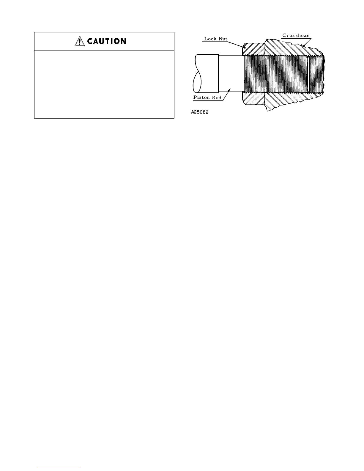
PISTON RODS – Pistons should be assembled on the
rod taper WITH THE THIN NUT NEXT TO THE PISTON HUB AND THE THICK NUT ON THE OUTSIDE.
This is important as the outer nut carries the load. Slush
service rods use one elastic collar–type locknut per
rod. Rods should be threaded into the crosshead as
shown in FIGURE 6, leaving approximately one thread
of the locknut over the relieved portion of the rod as a
protection to the threads.
FLUID V AL VES – V alves are easily installed in their individual valve pots. Care should be exercised to tighten
the valve cover nuts as uniformly as possible, tightening each nut a little at a time until all are tight. Valve
FIGURE 6 – PISTON ROD
seats and the bore in the deck must be perfectly clean
and free from oil or grease.
V alve seats can be removed with a puller which can be
purchased from Gardner Denver Machinery Inc.
ST ARTING A NEW PUMP – Pumps are shipped from
the factory without oil in the crankcase. The hood
should be removed and the power end examined and
cleaned if necessary . The pump may have been in storage or in the yard for some time and as a consequence
dirt may have entered the crankcase. Parts may have
been robbed from the pump during storage and not replaced. All nuts and screws should be tightened.
The jackshaft bearings have been supplied with grease
at the factory and no grease should be added at this
time, unless bearings have been disturbed.
Be sure all valves in the discharge line are open. No
valve should be installed between the pump and pressure relief valve in discharge line.
To prevent excessive wear on the fluid pistons and
packing when starting, remove a suction valve cover
plate on each side of the fluid end and prime the pump.
Pump should be started slowly , if possible, and should
be operated for several hours with practically no discharge pressure. Check oil level as it may be necessary to add a small quantity of oil to compensate for that
adhering to the walls of the crankcase and the moving
parts. The pump may then gradually be brought up to
full speed and full working pressure. Watch for undue
heating or abnormal noise in the working parts. Check
all joints in the suction line to be sure there are no air
leaks.
Make certain pump is rotating in the correct direction.
Refer to FIGURE 7, page 11.
3–600 Page 10
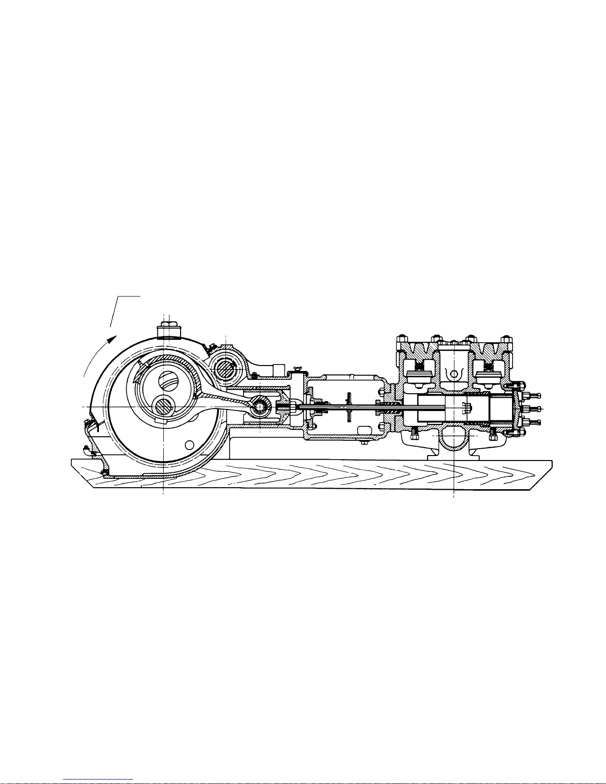
3–600 Page 11
FIGURE 7 – ROTATION OF ECCENTRIC
PREFERRED ROT ATION OF ECCENTRIC
SECTION 3
ROUTINE MAINTENANCE & SERVICE INSTRUCTIONS
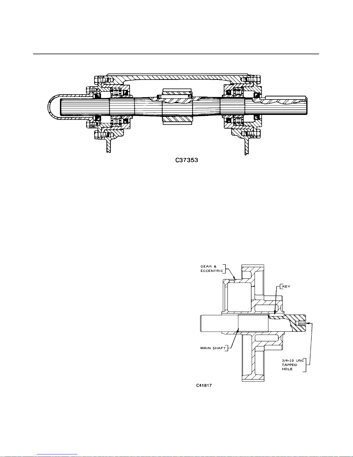
FIGURE 8 – JACKSHAFT ASSEMBLY
Daily Care – The pump should be kept clean, lubri-
cated properly and stuffing boxes examined daily . With
reasonable care, the pump can be expected to give
long and trouble–free life.
Occasional Inspection – It is recommended that the
fluid valves be examined occasionally to see that excessive wear or cutting has not impaired their efficiency
and any damaged or worn parts should be replaced.
Fluid end must always be drained when exposed to
freezing weather during idle periods.
SERVICE INSTRUCTIONS
Removal of Jackshaft – To remove the jackshaft, it is
necessary to remove the bearing housings from both
sides of the pump. The bearing outer races and rollers
come off with the housings. The bearings inner races
and the seal bushings are pressed on the jackshaft and
need not be removed unless replacement is necessary .
The jackshaft can be lifted clear of the gear teeth and
removed. The jackshaft is not interchangeable end for
end, hence, it must be reinstalled in the same way it
was removed.
Installation of Jackshaft Oil Seals – The jackshaft
roller bearings are provided with a separate inner and
outer oil seal. The correct assembly of these seals is
with seal lips facing bearings.
bly. To remove the gear and eccentric, it is necessary
to remove the main shaft. The main shaft must be removed from the side of the pump in which the end of the
shaft contains a 3/4–10 UNC tapped hole. This is the
end of the shaft that also contains the main shaft to eccentric key. (See FIGURE 9.) It is advisable to have
new shaft seals as these seals can rarely be used the
To Remove Crosshead Pin From FXF and FXG
Pumps – The crosshead pin can be removed from the
FXF and FXG only by removing the entire gear assem-
FIGURE 9 – ECCENTRIC AND MAIN SHAFT ASSEMBLY
3–600 Page 12
To Install Main Bearings For All Pumps –
1. Install eccentric with gear teeth in correct position
in frame.
2. Install main shaft through opening in frame and
through eccentric.
3. Heat and press bearing cones to shaft.
4. Install bearing cups.
A41503
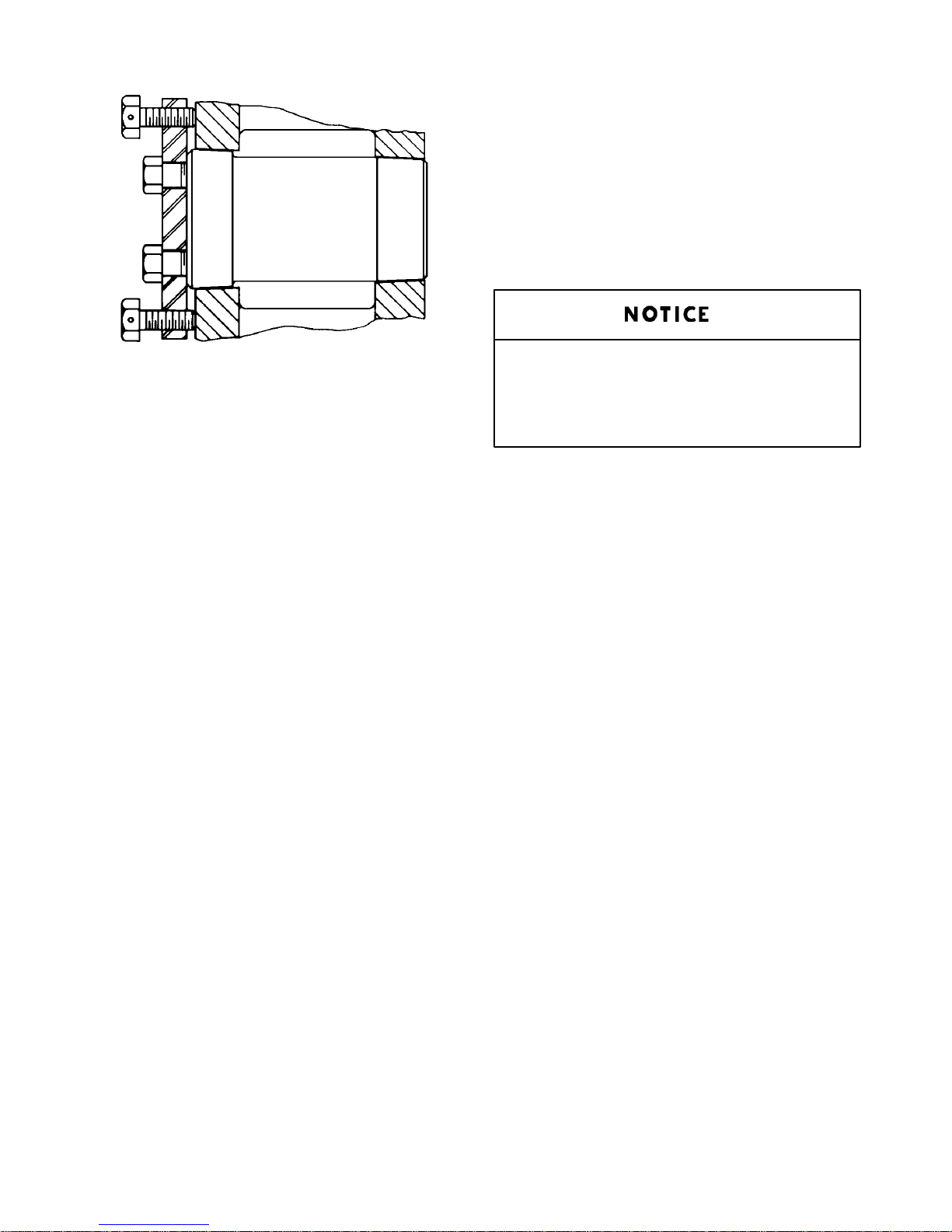
FIGURE 10 – CROSSHEAD PIN REMOVAL–FXX, FXD & FXE
second time. Remove shaft through eccentric with
hammer and wood block and the bearing cone and seal
bushing on the side opposite the tapped hole will slip off
the shaft.
The gear assembly with connecting rods and crossheads can all be pulled out through the hood opening
after the main shaft has been removed. The piston rods
of course must be screwed out of the crossheads before the assembly can be taken from the frame. Crosshead pins are straight and are held in place in the crossheads with set screws.
To Remove Crosshead Pin From FXX, FXD and
FXE Pumps – The inspection plates on the sides of the
frame should be removed. Two hexagon head cap
screws are used to hold the crosshead pin to the crosshead. These are the two screws in the corners of the
plate over the crosshead pin. Take these screws out
and insert them in the tapped holes in the adjacent corners of the plate and by exerting sufficient pressure
with these screws the crosshead pin will come out. A
little persuasion with a drift driven against the crosshead near the outer end of the crosshead pin will help.
To remove the gear and eccentric it is necessary to remove the main shaft and piston rods. The main shaft
must be removed from the side of the pump in which the
shaft contains a 3/4–10 UNC tapped hole. This is the
end of the shaft that also contains the main shaft to eccentric key . (See FIGURE 9, page 12.) Support eccentric on blocking and drive shaft through eccentric with
hammer and wood block. The bearing cone and seal
sleeve, on the side opposite the tapped hole, will slip off
the shaft.
There should be no space between
the bearing cones and seal bushing
or between the seal bushing and eccentric hub.
5. Install gasket and end plate on one side.
6. Take up end plate on other side snugly with cap
screws.
7. Check the gap between plate and frame housing
with shims. Determine shims required to fill the
gap. When you have determined the shims required to fill the gap, remove 0.001 to 0.003 inches
(0.0254 to 0.0762 mm) of shims.
8. Remove end plate and install remaining shims.
9. Mount and secure plate.
FXE Main Gear and Eccentric – This pump is
constructed with a separate gear bolted to the eccentric. Refer to page 18 for screw torque specifications.
MAINTENANCE OF SPARE REPAIR PARTS – Although operating conditions vary widely , it is suggested
that a stock of spare replacement parts be maintained
to insure against loss of pump operation. It is considered good practice to keep spare fluid valves, pistons,
piston rods, packings, gaskets, etc. on hand. A recommended list of such parts may be secured from Gardner Denver Customer Service, the Master Distribution
Center (MDC), or your local authorized Gardner Denver Distributor.
ORDERING OF REPAIR PARTS – Repair parts lists
with sectional views are available for any Gardner Denver power pump and may be secured from Gardner
Denver Customer Service, the Master Distribution
Center (MDC), or your local authorized Gardner Denver Distributor.
3–600 Page 13
When ordering parts lists or repairs, always give size
and serial number of pump. Serial number is stamped
on the pump nameplate attached to frame and also on
a raised pad located on upper side of the power frame
at the fluid cylinder end.
If the serial number cannot be identified, obtain several
photographic views of the power frame and fluid cylinders, including part numbers of principal castings
which should furnish us clues as to the identity of the
pump.
SPECIAL CARE OF PUMP IN STORAGE – Piston rod
packing and piston packing must be removed, if the
pump is not put in service immediately. Permitting
packing to remain in an idle pump for a period of time
will tend to create rusting and pitting of liner bore and
piston rods.
Puller kit parts for removing valve seats, liners and
crosshead pin bushings may be purchased from Gardner Denver Machinery Inc.
OPERA TING SPEEDS AND PRESSURES – See bulletins for operating speeds and pressures for type of
service.
All displacements are theoretical with piston rod volume deducted. For actual delivery deduct from 5% to
10% for slippage using 10% at maximum RPM.
Pressures are maximum permissible
with rated maximum piston rod loads
and MUST NEVER BE EXCEEDED.
While it is true that reducing the speed reduces the
horsepower practically in direct proportion, the piston
load for which the pump is designed is a function of the
fluid pressure against the piston. Reducing the speed
to half and doubling the pressure requires approximately the same horsepower but results in 100% overload on the power end.
Maximum input BHP and shaft RPM shown in bulletins
MUST NEVER BE EXCEEDED under any operating
conditions. These speeds are recommended for favorable suction conditions and consideration must be given to viscosity and character of fluid.
DO NOT operate these pumps below
40 RPM as this will hinder proper lubrication.
3–600 Page 14

SECTION 4
DIMENSIONS & RUNNING CLEARANCES
POWER END OIL STOP HEAD DIMENSIONS
Stuffing Box Net Depth Of
Power Size Rod Diameter Diameter Stuffing Box
End
Model Inches mm Inches mm Inches mm Inches mm
FXF 5 127 15/16 23.8125 1–3/4 44.45 7/8 22.225
FXG 6 152.4 1 25.4 1–13/16 46.0375 7/8 22.225
FXX 8 203.2 1–1/2 38.1 2–1/2 63.5 1–1/8 28.575
FXD 10 254 1–1/2 38.1 2–1/2 63.5 1–5/8 41.275
FXE 10 254 1–1/2 38.1 2–1/2 63.5 1–5/8 41.275
FLUID END PISTON ROD STUFFING BOX DIMENSIONS
* Stuffing Box Net Depth Of
Power Fluid Size Rod Diameter Diameter Stuffing Box
End End
Model Type Inches mm Inches mm Inches mm Inches mm
FXF ALL 4 x 5 101.6 x 127.0 15/16 23.8125 1–3/4 44.45 2–1/16 52.3875
FXG ALL 5 x 6 127.0 x 152.4 1 25.4 1–13/16 46.0375 2–3/8 60.325
FXX D, H, 5 x 8 127.0 x 203.2 1–1/2 38.1 2–1/2 63.5 1–1/8 28.575
FXD M, Q, or or 1–1/2 38.1 2–1/2 63.5 3–1/8 79.375
FXE & U 5 x 10 127.0 x 254.0
B, C, 5 x 8 127.0 x 203.2 1–1/2 38.1 2–1/2 63.5 1–1/8 28.575
FXX F, G, or or 1–1/2 38.1 2–1/2 63.5 3–1/8 79.375
FXD K, L, 5 x 10 127.0 x 254.0
FXE P, S,
& T
FXX A, E, 5 x 8 190.5 x 203.2 1–1/2 38.1 2–1/2 63.5 1–1/8 28.575
FXD J, N, or or 1–1/2 38.1 2–1/2 63.5 3–1/8 79.375
FXE & R 5 x 10 190.5 x 254.0
* Refer to Unit Nameplate and Parts List Manual Matrix, Column 4, for Fluid Cylinder Descriptions.
3–600 Page 15
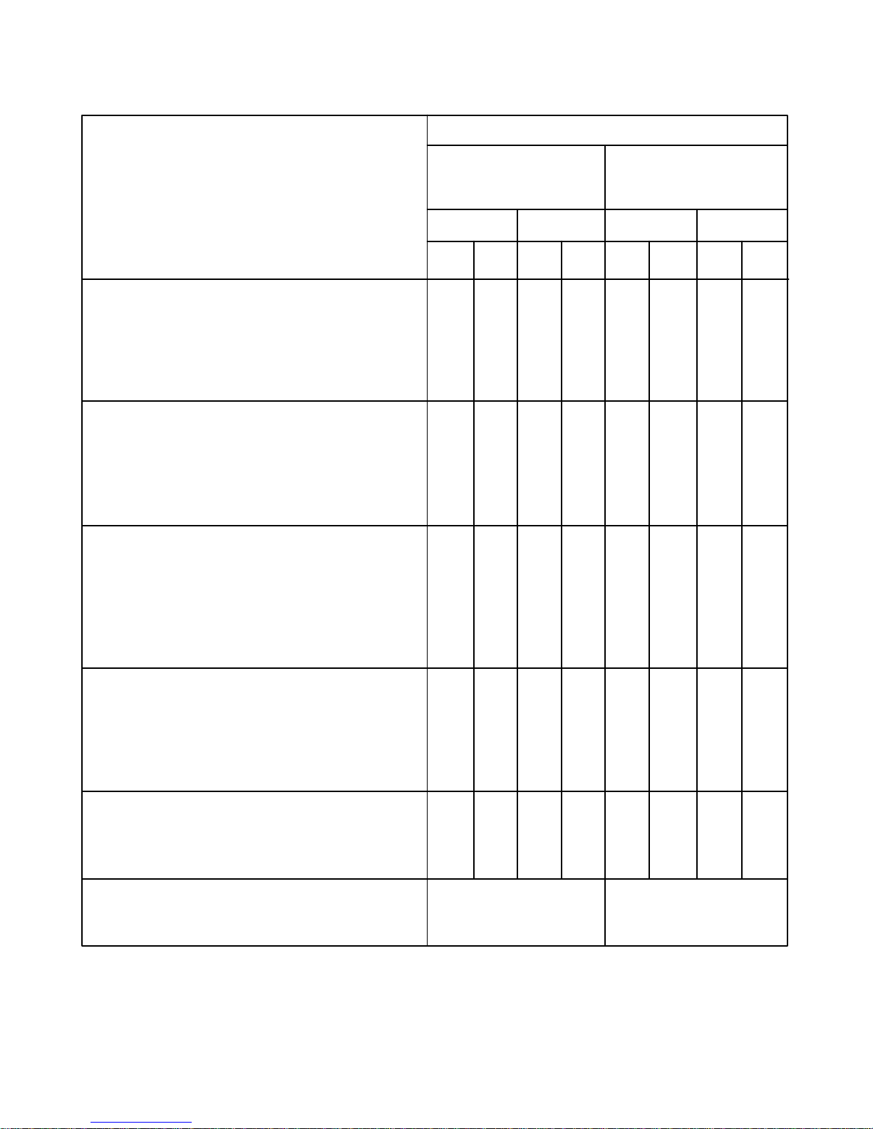
DAT A FOR FXD, FXE, AND FXX POWER PUMPS
POWER END AND STROKE
RECOMMENDED RUNNING CLEARANCES FXD & FXE FXX
(Actual dimensions are for new pumps and are 10 In. (254.0 mm) Stroke 8 In. (203.2 mm) Stroke
possible cumulative tolerances.) (Condemnable
indicates replacement necessary.) Inches mm Inches mm
Min. Max. Min. Max. Min. Max. Min. Max.
a. ROLLER TYPE MAIN BEARINGS
Refer to Page 13.
Bearing Preload .001T .003T .025T .076T .001T .003T .025T .076T
Condemnable when pitting, scaling, mis–
alignment, excessive wear or noise occurs.
b. CONNECTING ROD LINER TO ECCENTRIC
Actual .011 .022 .279 .559 .009 .017 .229 .432
Feeler Gauge .010 .021 .254 .533 .008 .016 .203 .406
Condemnable when liner knocks or
clearance equals .040 1.016 .035 .889
c. CROSSHEAD PIN
Feeler Gauge .0015 .002 .038 .051 .0015 .002 .038 .051
Condemnable – Replace pressed–in type
bushings when a .006” (.152 mm) feeler
gauge can be inserted between the pin and
bushing or when the crosshead pin knocks.
d. CROSSHEAD OR SHOE TO FRAME
Actual .005 .013 .127 .330 .005 .013 .127 .330
Feeler Gauge .004 .012 .102 .305 .004 .012 .102 .305
Condemnable when crosshead knocks or
clearance equals .060 1.524 .060 1.524
e. JACKSHAFT ROLLER BEARING
Condemnable between roller and race
.016 – .018” (.406 – .457 mm).
GEAR RATIO 6.0 4.71
3–600 Page 16
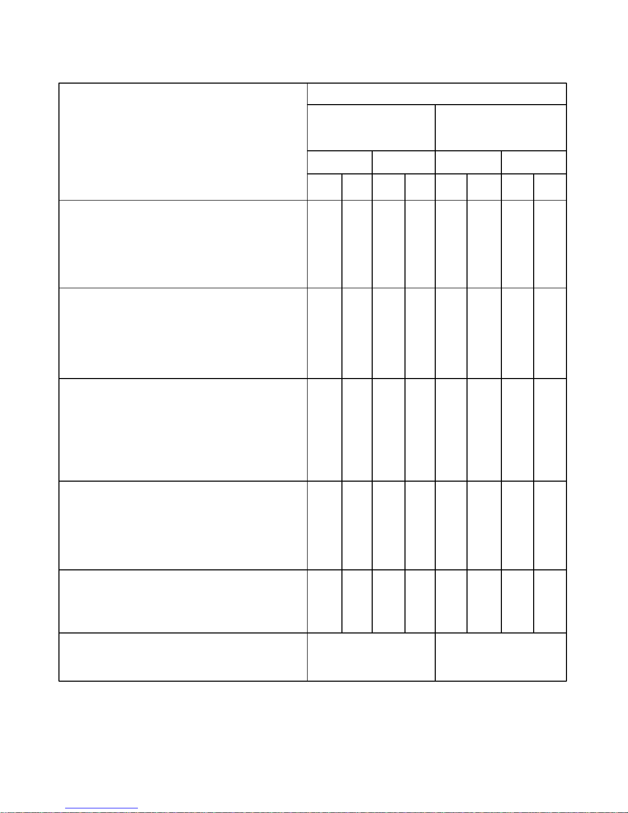
DAT A FOR FXG AND FXF POWER PUMPS
POWER END AND STROKE
RECOMMENDED RUNNING CLEARANCES FXG FXF
(Actual dimensions are for new pumps and are 6 In. (152.4 mm) Stroke 5 In. (127.0 mm) Stroke
possible cumulative tolerances.) (Condemnable
indicates replacement necessary.) Inches mm Inches mm
Min. Max. Min. Max. Min. Max. Min. Max.
a. ROLLER TYPE MAIN BEARINGS
Refer to Page 13.
Bearing Preload .001T .003T .025T .076T .001T .003T .025T .076T
Condemnable when pitting, scaling, mis–
alignment, excessive wear or noise occurs.
b. CONNECTING ROD LINER TO ECCENTRIC
Actual .007 .015 .178 .381 .006 .014 .152 .356
Feeler Gauge .006 .014 .152 .356 .005 .013 .127 .330
Condemnable when liner knocks or
clearance equals .030 .762 .030 .762
c. CROSSHEAD PIN
Feeler Gauge .0005 .0010 .0127 .0254 .0005 .0010 .0127 .0254
Condemnable – Replace pressed–in type
bushings when a .006” (.152 mm) feeler
gauge can be inserted between the pin and
bushing or when the crosshead pin knocks.
d. CROSSHEAD OR SHOE TO FRAME
Actual.003 .010 .076 .254 .003 .010 .076 .254
Feeler Gauge .002 .009 .051 .229 .002 .009 .051 .229
Condemnable when crosshead knocks or
clearance equals .060 1.524 .060 1.524
e. JACKSHAFT ROLLER BEARING
Condemnable between roller and race
.016 – .018” (.406 – .457 mm).
GEAR RATIO 4.72 4.88
3–600 Page 17

TORQUE SPECIFICA TIONS
POWER FXD_ FXD_ FXD_ FXF
END FXE _ FXE_ FXE_ FXG
MODEL FXX _ FXX_ FXX_
ABD
* FLUID E C H
CYLINDER J F M ALL
TYPE N G Q
RKU
(Column 4 L
of Matrix) P
S
T
ft–lbs kg–m ft–lbs kg–m ft–lbs kg–m ft–lbs kg–m
Fluid Cylinder to Frame 210 29.0 590 81.6 590 81.6 260 36.0
Connecting Stud Nuts
Fluid Cylinder ––– ––– ––– ––– 590 81.6 ––– –––
Head Stud Nut
Fluid Cylinder Liner 25 3.5 25 3.5 25 3.5 25 3.5
Set Screw
Suction Manifold to ––– ––– ––– ––– 260 36.0 ––– –––
Fluid Cylinder
Discharge Manifold to ––– ––– ––– ––– 260 36.0 ––– –––
Fluid Cylinder
Suction Manifold 260 36.0 260 36.0 260 36.0 150 20.7
Flange Nut
Discharge Manifold 260 36.0 ––– ––– 800 110.6 150 20.7
Flange Nut
Piston Rod Nut 525 72.6 525 72.6 525 72.6 260 36.0
(Slush–Proof Rod)
FXE ONLY
ft–lbs kg–m
Main Gear to Eccentric Screw 75 10.4
* Refer to Unit Nameplate and Parts List Manual Matrix, Column 4, for Fluid Cylinder Descriptions.
3–600 Page 18

SECTION FIVE
TROUBLESHOOTING
FAILURE T O DELIVER REQUIRED VOLUME:
FAILURE T O CREATE RATED PRESSURE:
(a) Pump not primed.
(b) Insufficient speed.
(c) Fluid liner worn.
(d) Suction lift too high.
(e) Air leaks in suction or stuffing boxes.
(f) Foot valve too small or clogged.
(g) Suction pipe not immersed deep enough.
(h) Fluid piston packing worn.
(i) Fluid valves worn.
(j) Insufficient prime mover horsepower.
(k) Piston loose on rod.
(a) Insufficient prime mover horsepower.
(b) Slippage in drive.
PUMP LOSES CAP ACITY AFTER STARTING:
PUMP VIBRA TES
(c) High back pressure.
(d) Piston rings in fluid end binding.
(e) Pistons improperly packed.
(f) Valves not holding.
(g) Leakage past fluid piston rings.
(h) Leakage past liner packing.
(i) Liners worn.
(a) Leaky suction line.
(b) Suction lift too great.
(c) Entrained vapors in the fluid, especially if fluid is
warm.
(a) Fluid pistons improperly packed.
(b) Foundation not sufficiently rigid.
(c) Fluid piston packed too tight.
(d) Fluid valves improperly seated.
(e) Improper discharge line.
NOISY FLUID V ALVES:
(a) Usually due to air leaks or failure of the fluid end to
completely fill due to faulty suction conditions.
(b) Valves not seating tightly.
3–600 Page 19

GARDNER DENVER
WARRANTY
R
D OPIR PUMPS
GENERAL PROVISIONS AND LIMIT ATIONS
Gardner Denver Machinery Inc. (the “Company”) warrants to each original retail purchaser (“Purchaser”) of its
new products from the Company or its authorized distributor that such products are, at the time of delivery to the
Purchaser, made with good material and workmanship.
No warranty is made with respect to:
1. Any product which has been repaired or altered
in such a way , in the Company’s judgment, as to
affect the product adversely.
2. Any product which has, in the Company’s judgment, been subject to negligence, accident, improper storage, or improper installation or application.
3. Any product which has not been operated or
maintained in accordance with the recommendations of the Company.
4. Components or accessories manufactured,
warranted and serviced by others.
5. Any reconditioned or prior owned product.
Claims for items described in (4) above should be submitted directly to the manufacturer.
WARRANTY PERIOD
The Company’s obligation under this warranty is limited
to repairing or, at its option, replacing, during normal
business hours at an authorized service facility of the
Company, any part which in its judgment proved not to
be as warranted within the applicable Warranty Period
as follows.
Except for the products or components listed below , the
Warranty Period for all products is 1,250 hours of operation or three (3) months after start–up, not to exceed 120
days after delivery to Purchaser, whichever occurs first.
The exceptions are as follows:
1. Power end is warranted for twelve (12) months
from date of start–up or eighteen (18) months
from date of delivery to the Purchaser, whichever occurs first.
2. Forged steel fluid cylinder is warranted for 90
days from date of installation.
3. Expendable fluid end parts, including, but not
limited to, valves, valve parts, packing, liners
and pistons, are not covered by this warranty
due to variable abrasive nature of material
pumped.
LABOR TRANSPORTA TION AND INSPECTION
The Company will provide labor, by Company representative or authorized service personnel, for repair or replacement of any product or part thereof which in the
Company’s judgment is proved not to be as warranted.
Labor shall be limited to the amount specified in the
Company’s labor rate schedule.
Labor costs in excess of the Company rate schedules
caused by, but not limited to, location or inaccessibility
of the equipment, or labor provided by unauthorized service personnel is not provided for by this warranty.
All costs of transportation of product or parts claimed not
to be as warranted and, of repaired or replacement parts
to or from such service facility shall be borne by the Purchaser. The Company may require the return of any part
claimed not to be as warranted to one of its facilities as
designated by the Company, transportation prepaid by
the Purchaser, to establish a claim under this warranty.
Replacement parts provided under the terms of this warranty are warranted for the remainder of the Warranty
Period of the product upon which installed to the same
extent as if such parts were original components.
WARRANTY REGISTRATION VALIDATION
A warranty registration form is provided with each machine. The form must be completed by the Purchaser
and mailed within ten days after machine start–up to validate the warranty.
DISCLAIMER
THE FOREGOING WARRANTY IS EXCLUSIVE AND
IT IS EXPRESSLY AGREED THAT, EXCEPT AS TO
TITLE, THE COMPANY MAKES NO OTHER WARRANTIES, EXPRESSED, IMPLIED OR STATUTORY,
INCLUDING ANY IMPLIED WARRANTY OF MERCHANTABILITY.
THE REMEDY PROVIDED UNDER THIS WARRANTY
SHALL BE THE SOLE, EXCLUSIVE AND ONLY REMEDY AVAILABLE TO PURCHASER AND IN NO CASE
SHALL THE COMPANY BE SUBJECT TO ANY
OTHER OBLIGATIONS OR LIABILITIES. UNDER NO
CIRCUMSTANCES SHALL THE COMPANY BE
LIABLE FOR ANY SPECIAL, INDIRECT, INCIDENTAL
OR CONSEQUENTIAL DAMAGES, EXPENSES,
LOSSES OR DELAYS HOWSOEVER CAUSED.
No statement, representation, agreement, or understanding, oral or written, made by any agent, distributor,
representative, or employee of the Company which is
not contained in this Warranty will be binding upon the
Company unless made in writing and executed by an officer of the Company.
This warranty shall not be effective as to any claim which
is not presented within 30 days after the date upon which
the product is claimed not to have been as warranted.
Any action for breach of this warranty must be commenced within one year after the date upon which the
cause of action occurred.
Any adjustment made pursuant to this warranty shall not
be construed as an admission by the Company that any
product was not as warranted.
BE–13 R 10/96

 Loading...