

Gardner Denver Elmo Rietschle V-VWZ Series, Elmo Rietschle V-VWZ 252, Elmo Rietschle V-VWZ 102, Elmo Rietschle V-VWZ 162, Elmo Rietschle V-VWZ 402 Instruction And Service Manual

Betriebs- und Serviceanleitung
Reparaturanleitung
Frischölgeschmierte Drehschieber-Vakuumpumpen
V-VWZ
V-VWZ 102
V-VWZ 162
V-VWZ 252
V-VWZ 402
- 1 -
B 117
1.4.99
Gardner Denver
Schopfheim GmbH
Postfach 1260
79642 SCHOPFHEIM
GERMANY
Fon +49 7622 / 392 - 0
Fax +49 7622 / 392 - 300
e-mail: er.de@
gardnerdenver.com
www.gd-elmorietschle.com

Inhaltsverzeichnis Seite
Betriebs- und Service anleitung VWZ 102 – VWZ 402
1. Allgemein 3
2. Eignung 3
3. Ausführungen und Aufbau 3
3.1 Ausführungen 3
3.2 Aufbau 4
3.3 Datenblätter und Ersatzteillisten 5
3.4 Mögliches Zubehör 5
3.5 Typische Anwendungsgebiete 5
4. Arbeitsweise 6
4.1 Pumpe 6
4.2 Überströmventil 6
4.3 Ölschmierung 6
4.4 Abdichtungen 6
5. Installation 6
5.1 Mechanische Installation 6
5.1.1 Aufstellung 6
5.1.2 Saugseite 6
5.1.3 Abluftseite 6
5.2 Elektrische Installation 7
5.2.1 Allgemein 7
5.2.2 Richtwerte für die Einstellung des Motorschutzrelais 7
5.2.3 Elektrische Anschlüsse für den Motor und Steuerung der Kontroll-Einrichtungen 7
5.2.4 Klemmkastenbelegung umlaufgekühlte Version 7
6. Betrieb 8
6.1 Kühlfl üssigkeit 8
6.1.1 Durchlaufkühlung 8
6.1.2 Umlaufkühlung 8
6.1.3 Kühlwasserüberwachung 8
6.2 Ölschmierung 9
6.3 Ölschmierpumpe 9
6.4 Inbetriebnahme 9
7. Wartung 9
7.1 Öldosierpumpe 9
7.2 Ölnebelabscheider 10
7.2.1 Wartung des Ölnebelabscheiders 10
8. Störungsbehebung 10
8.1 Überstrom an der Pumpe 10
8.2 Abfall des Vakuums 10
8.3 Hoher Ölverbrauch 10
Reparaturanleitung VWZ 102 – VWZ 402
1. Demontage und Montage des Kühlergehäuses 11
2. Wechsel der ND- und HD-Verdichterstufen 11
2.1 Demontage der Verdichterstufen 11
2.2 Montage der Verdichterstufen 11
3. Demontage und Montage des Antriebs 11
4. Wechsel der Kupplungsgummi und der Kupplungsbolzen 12
4.1 Am Antrieb 12
4.2 An der Verdichterstufe 12
5. Reparaturen an der B-Seite der Verdichterstufen 12
5.1 Demontage der Lagerteile und Dichtungen 12
5.2 Montage der Lagerteile und Dichtungen 13
6. Wechsel der Lamellen 14
7. Reparaturen an der A-Seite der Verdichterstufen 14
7.1 Demontage der Lagerteile und Dichtungen 14
7.2 Monatage der Lagerteile und Dichtungen 15
8. Reparaturen am Getriebe 16
8.1 Demontage und Montage des Getriebegehäuses 16
8.2 Wechsel der Stirnräder und Kugellager im Getriebegehäuse 16
8.3 Wechsel der Lager, Wellendichtringe und Dichtungen im Anschlussgehäuse 17
9. Sonstige Reparaturarbeiten 17
9.1 Reinigung der Saug- und Ablufträume im Anschlussgehäuse 17
9.2 Wechsel der Ventilteile am Überströmventil 17
10. Vorgehensweise bei einer Einlagerung von ölgeschmierten Drehschieber-Vakuumpumpen 17
- 2 -

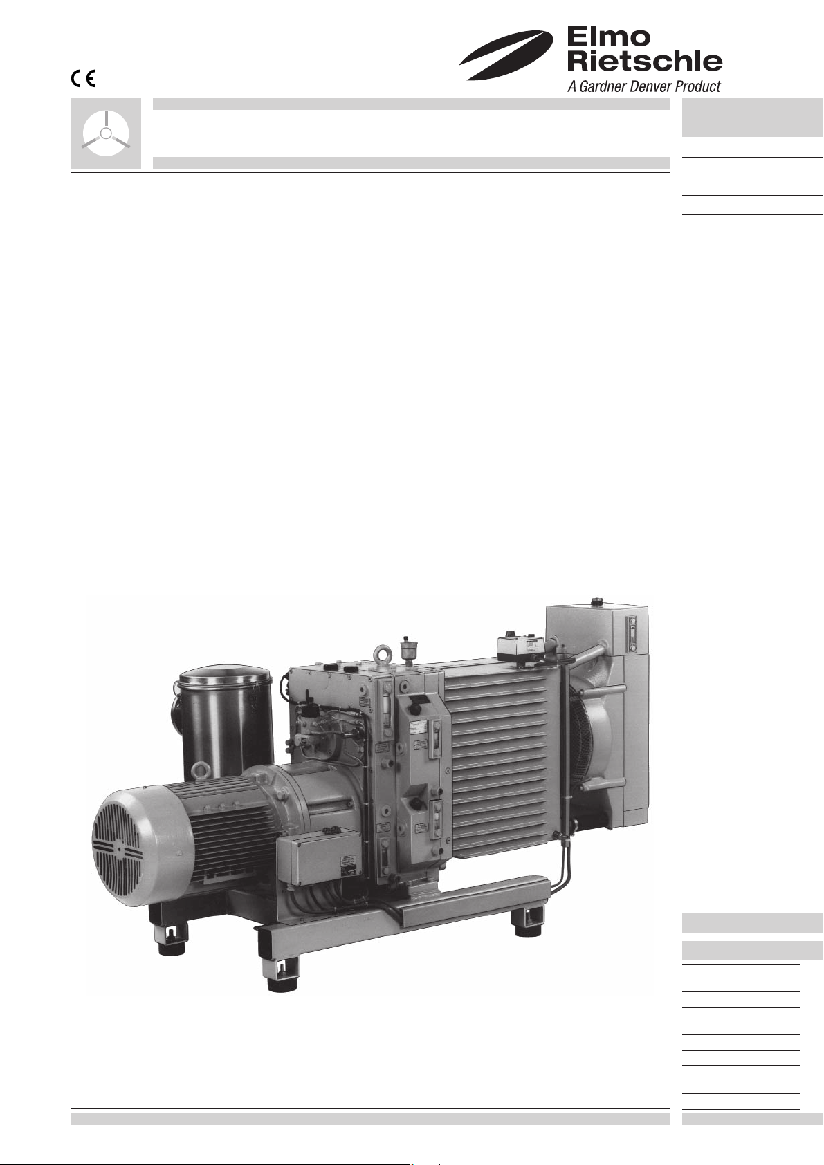
VWZ 402 mit Umlaufkühlung
BETRIEBS- UND SERVICE ANLEITUNG
1
1. Allgemein
Alle Pumpen, die aus irgendwel-
chen Gründen (z.B. Wartung) an
uns zurückgeschickt werden, müssen
von Schad- und Giftstoffen frei sein.
Eine entsprechende Bescheinigung ist
vorzulegen!
Ex-Schutz-Sicherheitsvorkehrungen für
Gesamt-Anlagen in welchen Vakuumpumpen eingesetzt werden, sind kundenseits
zu überprüfen und zu installieren. Die
Abstimmung muss mit den örtlichen zuständigen Sicherheitsbehörden (TÜV) oder
Gewerbeaufsichtsamt erfolgen.
2. Eignung
Die Vakuumpumpen VWZ eignen sich besonders zum Fördern von extrem feuchten
und aggressiven Gasen. Die Wasserdampfverträglichkeit ist nahezu unbegrenzt.
Die Umgebungstemperatur und
die Ansaugtemperatur darf zwi-
schen 5 und 40
o
C liegen. Bei Temperaturen außerhalb dieses Bereiches bitten
wir um Rücksprache.
Flüssigkeiten und feste Stoffe dürfen
nicht abgesaugt werden.
Förderung von explosiven Dämpfen
und Gasen nur nach Rücksprache mit
Rietschle.
Für den Betrieb in explosionsgefährdeten
Räumen müssen Motoren mit entsprechender Ex-Schutz-Klasse eingesetzt
werden.
Bei Aufstellung der Vakuumpum-
pe auf Höhen über 1000 m ü. M.
macht sicht eine Leistungsminderung
bemerkbar. In diesem Fall bitte wir um
Rücksprache.
Bei Anwendungsfällen, wo ein unbeabsichtigtes Abstellen oder ein Ausfall der
Vakuumpumpe zu einer Gefährdung von
Personen oder Einrichtungen führt, sind
entsprechende Sicherheitsmaßnahmen
anlagenseits vorzusehen.
VWZ 402 mit Durchlaufkühlung
2
3. Ausführungen und Aufbau
3.1 Ausführungen
Die Typenreihe VWZ gibt es in 7 Baugrößen wobei hier nur die Baugrößen mit einem Saugvermögen von 100, 160, 250 und 400
3
/h behandelt werden. Alle Typen erreichen Verdichtungsenddruck von 0,5 mbar (abs.). Die Kühlung erfolgt mittels Flüssigkeit.
m
Dabei unterscheiden wir zwei verschiedene Kühlsysteme:
1. Die Umlaufkühlung (siehe Bild 1) erfolgt mit Hilfe eines Wasser/Luft-Wärmeaustauschers, der durch einen separat angetrie-
benen Axialventilator gekühlt wird. Dieser Ventilator wird thermostatabhängig gesteuert.
2. Bei der Durchlaufkühlung (siehe Bild 2) wird mit einem Kühlwasser-Regulierventil, das in Abhängigkeit der Kühlwasser-Aus-
trittstemperatur gesteuert wird, der Kühlwasserdurchfl uss reguliert.
- 3 -

3.2 Aufbau (Bild 3 und 4)
Die VWZ besteht aus der Getriebe-Einheit (Y
Y
, R1) und den Abscheidesystemen (Z, J1, J2, J3) auf der Saug- und Auspuff-Seite (Zubehör). Die Pumpen sind wassergekühlt.
40
), den Anschlusseinheiten (S1, S2), der Ölversorgung (L1 bis L8), dem Kühlsystem (R,
3
Ein eingebautes Überströmventil (Q) gewährleistet das Einschalten und Betreiben der Pumpe in jedem Druckbereich.
A Vakuum-Anschluss
B Abluft-Austritt
Antrieb
G
1
Kühlwassereinfüllstelle und
H
4
Sicherheitsventil
Kühlwasserkontrolle
I
4
Filterkerzen für Ölnebelabscheider
J
1
Manometer für Ölnebelabscheider
J
2
Ablasshahn für Ölnebelabscheider
J
3
L Ölpumpe
Ansaugleitung Ölpumpe
L
1
Leckölleitung Ölpumpe
L
2
Schmierung A-Seite ND
L3
Schmierung B-Seite ND
L4
Schmierung A-Seite HD
L5
Schmierung B-Seite HD
L6
Lagerschmierung ND-Stufe
L7
Lagerschmierung HD-Stufe
L8
Q Überströmventil
R Wasserkühler
Ventilator
R
1
Niederdruck (ND)-Stufe
S
1
Hochdruck (HD)-Stufe
S
2
U Sicherheits- und Betriebs temperaturthermostat
Kühlwasserentlüftung
U
2
Niveauwächter Kondensat/Öl
V
7
Y Frischölbehälter
Ölbehälter für Lager ND-Stufe
Y
1
Ölbehälter für Lager HD-Stufe
Y
2
Getriebe-Einheit
Y
3
Getriebeöl
Y
30
Kühlfl üssigkeit
Y
3
40
Z Ölnebelabscheider
- 4 -
4

3.3 Datenblätter und Ersatzteillisten
siehe folgende Datenblätter:
D 111 Durchlaufkühlung ➝ VWZ 102 – VWZ 402 (14)
D 117 Umlaufkühlung ➝ VWZ 102 – VWZ 402 (13)
siehe folgende Ersatzteillisten:
E 117/1 Teile der Grundeinheiten
E 117/2 Antrieb und Getriebeeinheit
E 117/3 Umlaufkühlung
E 117/4 Ölversorgung
E 117/5 Durchlaufkühlung
Z ➝ Ölnebelabscheider
➝ Spülmitteleinrichtung
Z
1
mit integriertem
Zusatzölbehälter
3.4 Mögliches Zubehör
Saugseitig:
• Absperrklappe
• Schnüffelventil
• Feststoff/Flüssigkeitsabscheider
• Kondensator
1
Ausblasseitig:
Z
• Ölnebelabscheider
• Kondensator
Allgemein:
• Elektrische Steuerung mit Vor- und
Nachlauf
• Spülmitteleinrichtung mit integr. Zu-
satzölbehälter
• Zusatzölbehälter
• Automatischer Kondensatablass
Z
3.5 Typische Anwendungsgebiete
• Vakuum-Trocknung
• Vakuum-Destillation
• Vakuum-Kristallisation
• Vakuum-Entgasung
• Vakuum-Verpackung von feuchten
Produkten
• Eindicken von Flüssigkeiten, Säften
7
und Extrakten
Z ➝ Ölnebelabscheider
➝ Vorabscheider
Z
2
Z
2
Z
8
- 5 -

4. Arbeitsweise
4.1 Pumpe
Die Verdichtereinheiten der VWZ arbeiten nach dem Drehschieberprinzip und sind frischölgeschmiert. Ihre Förder richtung ist von
oben nach unten. Deshalb fallen z.B. mitangesaugte Verunreinigungen oder Kondensate nach unten und können leicht abgeführt
werden.
4.2 Überströmventil
Zwischen der HD- und ND-Stufe befi ndet sich ein Überströmventil, das federbelastet ist. Dieses Überströmventil hat dabei folgende
Funktion: Beim Einschalten der Pumpe bei atmosphärischem Druck öffnet dieses Ventil auf Grund des entstehenden Überdruckes
zwischen ND- und HD-Stufe. Dieser Überdruck wird durch die höhere Saugleistung der ND-Stufe verursacht. Die Gase strömen
nun so lange direkt in den Auspuff, bis durch den abfallenden Ansaugdruck die Druckdifferenz zum Öffnen des Überströmventils
unterschritten ist. Bei gleicher Saugleistung der ND- und HD-Stufe werden die Gase zweistufi g gegen Atmosphäre verdichtet.
4.3 Ölschmierung
Die Lager der ND- und HD-Stufe, sowie die Zahnräder des Getriebes haben eine getrennte Öl-Kontaktschmierung mit jeweils
einem eigenen Ölbehälter.
Die Förderräume der Vakuumpumpe werden durch eine genau dosierte Verbrauchsschmierung mit Hilfe einer Öldosierpumpe
ständig mit Frischöl versorgt. Dieses Öl kann zusammen mit den von der Pumpe geförderten Medien über ein Abscheidesystem
ausgestoßen werden.
4.4 Abdichtung (Bild 9)
Die Rotorwelle (9 a) wird vom Innern
der Verdichterstufe (9 b) beidseitig mit
Wellendichtringen (9 c) abgedichtet. Zur
Entlastung dient die anliegende Gleitringdichtung (9 d/9 e), die gemeinsam mit den
Wellendichtringen auf auswechselbaren
Laufbüchsen (9 f) sitzen. Antriebseitig
übernimmt ein Wellendichtring (9 h) die
Abdichtung zum Kupplungsraum (9 k). Die
Welldichtringe (9 m) verhindern das Austreten von Getriebeöl aus dem Getriebe-Raum
(9 n) an der Getriebewelle (9 p).
9
5. Installation
5.1 Mechanische Installation
5.1.1 Aufstellung (siehe Datenblätter D 111 + D 117)
Bei betriebswarmer Pumpe können, in Abhängigkeit der eingestellten Betriebstemperatur, die Oberfl ächentempe-
raturen (insbesondere das Kühlerwassergehäuse (Y
Die VWZ-Vakuumpumpen arbeiten vibrationsfrei. Eine spezielle Bodenbefestigung ist nicht erforderlich. Beim Aufstellen ist darauf
zu achten, dass die Pumpe waagrecht installiert wird, und dass für Kontroll, Wartungs- und Reparaturarbeiten die Ölversorungseinheit, die Verdichtereinheiten, das Überstromventil, der Messwertgeber, der Motor und die Einheiten für das Kühlmedium leicht
zugänglich sind.
Kühlluft-Eintritt ist bei (E) und Kühlluft-Austritt ist bei (F), deshalb muss der Luft-Wasser-Kühler mindestens 0,5 m Abstand zur
nächsten Wand haben. Im Aufstellungsraum sollte die Umgebungstemperatur 40°C nicht überschreiten.
Wir empfehlen außerdem für Wartungsarbeiten motorseitig ca. 0,3 m und kühlerseitig ca. 0,6 m Wandabstand einzuhalten.
Die VWZ kann nur in horizontaler Einbaulage fehlerfrei betrieben werden.
Bei Aufstellung und Betrieb ist die Unfallverhütungsvorschrift »Verdichter« VBG 16 zu beachten.
5.1.2 Saugseite (siehe Datenblätter D 111 + D 117)
Saugleitung an (A) anschließen (genormter ISO-Flansch). Diese Rohrleitung sollte so kurz wie möglich sein. Ist sie länger als ca.
5 m, dann muss eine größere Nennweite als die des Pumpenfl ansches gewählt werden. Beim Verlegen ist darauf zu achten, dass
keine Spannungen auf die Pumpe einwirken (eventuell Federungskörper dazwischenbauen). Zum Schutz von Fest- und Flüssigstoffen sollten entsprechende Abscheideorgane saugseitig installiert werden (Zubehör).
Feststoffe größer als 5 μm und Flüssigkeitsschwall können zur Zerstörung der Verdichterstufen führen.
5.1.3 Abluftseite (siehe Datenblätter D 111 + D 117)
Beim Einsatz eines Ölnebelabscheiders wird die Abluftleitung an (B) angeschlossen. Wird die Abluftleitung direkt angeschlossen,
muss sie grundsätzlich von der Pumpe weg mit einem Gefälle verlegt werden.
Bei einer Steigleitungs-Ausführung muss möglichst nahe an der Pumpe ein Auffangbehälter für das Kondensat (mit Entleerungsmöglichkeit, Durchmesser von mindestens
1
/2“) installiert werden. Dabei muss unterhalb des Austrittfl ansches eine Überwachung
installiert sein. Dadurch wird ein Rückfl ießen von Kondensat in die Pumpe bei Nichtablassen verhindert.
Abluftwiderstand der Leitung darf 0,3 bar Überdruck nicht überschreiten.
)) über 70oC ansteigen, dort ist eine Berührung zu vermeiden.
4
- 6 -

5.2 Elektrische Installation
5.2.1 Allgemein (siehe Datenblätter D 111 + D 117)
Die elektrischen Motordaten sind auf dem Datenschild (N) bzw. dem Motordatenschild angegeben. Die Motoren entsprechen
DIN / VDE 0530 und sind in Schutzart IP 54 und Isolationsklasse B oder F ausgeführt. Das entsprechende Anschlussschema befi ndet
sich im Klemmenkasten des Motors. Die Daten des Motors und der Steuerung sind mit den Daten des vorhandenen Stromnetzes
zu vergleichen (Stromart, Spannung, Netzfrequenz, zulässige Stromstärke).
Motor über Motorschutzschalter anschließen (zur Zugentlastung des Anschluss-Kabels ist eine PG-Verschraubung vorzusehen).
Wir empfehlen die Verwendung von Motorschutzschaltern, deren Abschaltung zeitverzögert erfolgt, abhängig von einem evtl.
Überstrom. Kurzzeitiger Überstrom kann beim Kaltstart der Maschine auftreten.
Die elektrische Installation darf nur von einer Elektrofachkraft unter Einhaltung der EN 60204 vorgenommen werden.
Der Hauptschalter muss durch den Betreiber vorgesehen werden.
5.2.2 Richtwerte für die Einstellung des Motorschutzrelais
Die Richtwerte für die Einstellung des Motorschutzrelais entnehmen Sie den Unterlagen des Motorherstellers.
5.2.3 Elektrische Anschlüsse für den Motor und Steuerung der Kontroll-Einrichtungen
Alle elektrischen Anschlüsse für den Motor und für die Steuerung der Kontroll-Einrichtungen befi nden sich im Klemmenkasten. Jede
Anschlussklemme der Klemmenleiter hat eine Nummer und alle Anschlüsse für Motor und Kontroll-Organe sind einer bestimmten
Nummer zugeordnet (siehe Stromlaufplan Bild 10). Bei Nachrüstung oder Reparaturarbeiten ist diese Zuordnung der Nummern
für die Anschlüsse unbedingt einzuhalten. Funktionsstörungen lassen sich vermeiden und Fehlerquellen somit leichter fi nden.
5.2.4 Klemmkastenbelegung umlaufgekühlte Version
1 2 3 4 5 6 7 8 9 1011121314151617181920212223242526
1
thermostat
Durchlaufgekühlte Version ➝ ohne Ventilatormotor und Betriebs-
Saugventil
Schnüffelventil
Ventil Spülmitteleinrichtung
Ventil Frischöl
Ventil Ölnebelabscheider
Reserve
Sicherheitsthermostat
Betriebsthermostat
- 7 -
Niveau Vorabscheider
Niveau Spülmittel
Niveau Kühlwasser
Niveau Ölnebelabscheider
Niveau Frischöl
Reserve
10

6. Betrieb
6.1 Kühlfüssigkeit
Y
5
U
Y
25
U
U
41
1
31
T
V
4
6.1.1 Durchlaufkühlung (Bild 12)
Für die Inbetriebnahme der Pumpe (VWZ 102 – VWZ
402 (14)) wird zuerst die Wasserleitung am Schlauchanschluss (C) angeschlossen. Durch Eindrücken der
D
Ventilkappe bis zum Anschlag des SelbstschlussDurchgangsventil (U
häuse (Y
). Das Ventil muss so lange betätigt werden
4
) fl ießt Wasser in das Kühlerge-
4
bis Wasser aus dem Schlauchanschluss (D) austritt.
Dann Schlauch für den Abfl uss anschließen. Ist die
Abwasserleitung schon fest montiert, muss vor der
Füllung die Verschlussschraube (U25) zur Entlüftung
geöffnet werden. Nach Austritt des Kühlwassers
Öffnung wieder schließen. Die Abführung (D) des
Y
4
Kühlwassers aus dem Kühlergehäuse (Y4) muss
drucklos erfolgen.
Kühlwasserdruck größer als 0,3 bar Überdruck führt zur Zerstörung des Kühlwas-
sergehäuses.
Das thermostatische Wasserventil (U3) mit seinem
Fühler (U31) im Kühlergehäuse regelt den Durchfl uss
U
3
C
des Kühlwassers. Es hat einen Einstellbereich von
50°C-90°C. Je nach Erfordernis des Arbeitsbereiches
wird die Betriebstemperatur, die dann konstant bleiben muss, eingestellt. Am Thermometer (T) kann sie
abgelesen werden. Sollte aus irgend einem Grund
die Betriebstemperatur höher steigen, stellt der auf
U
5
dem Kühlergehäuse angebrachte Thermostat (U1)
bei 90°C die Pumpe ab. Diese Temperatur ist vom
Hersteller eingestellt und sollte nicht verstellt wer-
12
K
4
U
51
U
4
den. Sollten prozessbedingt höhere Temperaturen
notwendig sein, ist dies nach Rücksprache mit dem
Stammhaus möglich.
U
Y
5
U
2
21
41
U U
I
26
4
H
RY
4
Damit der Schmutz im einfl ießenden Kühlwasser das
thermostatische Wasserventil nicht verunreinigt und
in seiner Funktion behindert, ist ihm ein Schmutzfänger (U5) vorgeschaltet. Je nach Verschmutzung des
Kühlwassers ist nach angemessenen Zeitabständen
der Schmutzfänger zu warten. Verschlussschraube
(U51) öffnen und vorhandenes Sieb reinigen.
6.1.2 Umlaufkühlung (Bild 13)
Für die Inbetriebnahme der Pumpe (VWZ 102 – VWZ
402 (13)): Kühlfl üssigkeit an (H
) drucklos soweit ein-
4
füllen, bis der Füllstand die Mitte des Schauglases (I4)
erreicht hat. Grundsätzlich muss der Kühlfl üssigkeit
ein Frostschutzmittel (ca. 50%) beigemischt werden. Beide Flüssigkeiten sind vor dem Einfüllen gut
durchzumischen. Ein einfaches Zusammenschütten
ist wegen ihrer verschiedenen spezifi schen Gewichte
nicht ausreichend. Die Einfüllmengen entnehmen Sie
bitte dem Datenblatt D 117.
Das Ablassen der Kühlfl üssigkeit erfolgt durch Öffnen des Ablasshahnes (K4) am Kühlergehäuse (Y4)
und öffnen der Verschlussschraube (K41) am Kühler
(R). Zuvor zum Entlüften Verschlussschraube (U26)
herausschrauben.
13
Y
4
K
4
R
K
1
41
6.1.3 Kühlwasserüberwachung (Bild 12 und 13)
Bei der Pumpe (Durchlaufkühlung) überwacht der Sicherheitsthermostat (U
) die Temperatur des Kühlwassers.
1
Bei Inbetriebnahme der Pumpe (Umlaufkühlung) überwacht der Sicherheits- und Betriebstemperatur-Thermostat (U) die Temperatur
des Kühlwassers und übernimmt die Ein-/Ausschaltung des Axial-Lüfters (R1) um die Pumpe auf einer konstanten Betriebstemperatur zu halten. Nach der Inbetriebnahme ergibt sich im Kühlwassersystem ein Druck von ca. 0,3 bar. Über das Sicherheitsventil
(H4) wird weitersteigender Druck sofort ausgeglichen. Besonders bei Erst- und Nachfüllung von Kühlwasser bilden sich während
des Betriebes an der Oberfl äche Luftblasen, die durch das Schnellentlüftungsventil (U2) entweichen. Dabei muss die Gewindekappe (U21) auf dem Ventil, wenn die Pumpe arbeitet, mit 2-3 Gewindegängen geöffnet sein.
Sollte die Pumpe (Durch- oder Umlaufkühlung) an ihrem Standort der Frostgefahr ausgesetzt sein, ist die Pumpe durch geeignete
Maßnahmen zu schützen. Diese Betriebstemperatur kann, je nach Erfordernis, im Bereich von 50°-80°C eingestellt werden. Wenn
jedoch die Sicherheitstemperatur von 90°C erreicht wird, schaltet der Thermostat die Pumpe automatisch ab. Sollten prozessbedingt höhere Temperaturen notwendig sein, ist dies nach Rücksprache mit dem Stammhaus möglich.
- 8 -

6.2 Ölschmierung (siehe Datenblätter D 111 + D 117)
Die Pumpe wird mit gefüllten Ölvorratsbehältern (ausgenommen Frischöl)
versandt. Trotzdem sollten aus Sicherheitsgründen die Ölstände überprüft
Ölschmierpumpe
Weniger Öl Mehr Öl
werden. Voller Füllstand ist jeweils erreicht, wenn sich der Ölspiegel im oberen
Drittel des Ölstandsanzeigers befi ndet.
Schauglas: Frischöl (I), ND-Lager (I
), HD-Lager (I2), Getriebe (I3). Bei feh-
1
lendem Öl muss nachgefüllt werden. Öleinfüllstelle: Frischöl (H), ND-Lager
), HD-Lager (H2), Getriebe (H3). Für den Frischölbehälter ist serienmäßig
(H
1
ein Ölniveauschalter (V) eingebaut. Er stellt die Vakuumpumpe automatisch
ab sobald minimaler Ölstand erreicht wird. Nach dem Nachfüllen des Öles
kann die Vakuumpumpe wieder gestartet werden. Wir empfehlen folgende
Ölsorten: Bechem VBL 100, BP Energol RC 100, Esso Umlauföl 100, Mobil
Vakuumpumpenöl Heavy, Shell Tellus Öl C 100 oder Aral Motanol HK 100.
Andere Schmiermittel dürfen nur nach vorheriger Absprache mit dem Hersteller eingesetzt werden. Die vollständige Auswechslung des Lageröles und
des Getriebeöles sollte einmal jährlich durchgeführt werden. Bei extremen
Einsatzbedingungen müssen die Wartungsintervalle je nach Notwendigkeit
verkürzt werden. Ölempfehlungsschild (M), Ölablass ND-Stufe (K1) und HDStufe (K2). Auch die Auswechslung des Öles im Getrieberaum sollte man nach
ca. 3000 Betriebsstunden vornehmen (K
).
3
Messung des Frischölverbrauches: Frischöl bis zum oberen Strich des Schauglases (I) einfüllen. Pumpe 10 h in Betrieb nehmen. Anschließend wieder
Frischöl bis zum oberen Strich des Schauglases nachfüllen.
Frischölverbrauch = Nachfüllmenge / 10 h
Das Altöl ist gemäß den Umweltschutz-Bestimmungen zu entsorgen.
Bei Ölsortenwechsel Ölbehälter vollständig entleeren.
6.3 Ölschmierpumpe
Die Ölschmierpumpe wird werkseitig auf die erforderliche Fördermenge eingestellt.
Eine Veränderung dieser Menge darf nur nach Rücksprache mit Rietschle erfolgen.
Eine Veränderung der Ölmenge erfolgt durch Drehen der Regulierschrauben. Pro Umdrehung wird die Förderleistung um
ändert. Weniger Öl nach links; mehr Öl nach rechts.
Bei erstmaliger Inbetriebnahme, nach einer Stillstandszeit über 1 Woche, nach Demontage der Getriebeeinheiten,
nach Stufenwechsel, nach Reinigung der Ölpumpe und nach Arbeiten an den Ölleitungen muss mit Hilfe der Kurbel
Öl in die Leitungen gepumpt werden (ca. 150-200 Umdrehungen).
Ölverbrauch für VWZ und für VPA (VWZ + Rootsgebläse): l/h
VWZ 102 162 252 402
50 Hz 0,130 0,130 0,162 0,162
60 Hz 0,156 0,156 0,194 0,194
VPA 102. ... 162. ... 252. ... 402. ...
50 Hz 0,195 0,195 0,234 0,243
60 Hz 0,234 0,234 0,291 0,291
1
/3 ver-
6.4 Inbetriebnahme
Warnung –> Anlauf mit Zuleitungen
Beim Anlauf können durch Verunreinigungen in den Zuleitungen schwere Schäden an der Pumpe die Folge sein.
Zum Schutz der Pumpe muss beim Anlauf vom Betreiber
ein vakuumfestes Anlaufsieb (5 μm) saugseitig installiert
werden.
Pumpe zur Drehrichtungsüberprüfung kurz starten (Drehrichtungspfeil (O ➞ D 111 + D 117)). Als Zubehör kann antriebseitig
ein Freilauf vorgesehen werden, der bei falscher Drehrichtung
des Motors ein Mitlaufen der Vakuumpumpe verhindert.
Achtung! Beim Fördern von feuchten und aggressiven Medien
muss die Vakuumpumpe vor und nach dem Prozess gegen
die geschlossene Saugseite, jedoch offenem Schnüffelventil
(Zubehör) betrieben werden. Die Vor- bzw. Nachlaufzeit ist
prozessabhängig, beträgt aber üblicherweise zwischen 20 bis
30 Minuten.
Beim Vorlauf wird die Pumpe auf die Betriebstemperatur gebracht. So wird eine Kondensation feuchter Medien innerhalb
der Pumpe vermieden. Durch den Nachlauf werden Rückstände
ausgespült und gleichzeitig für den Stillstand konserviert.
7. Wartung
Bei Maßnahmen zur Instandhaltung, bei denen Per-
sonen durch bewegte oder spannungsführende Teile
gefährdet werden können, ist die Pumpe durch ziehen des
Netzsteckers oder Betätigen des Hauptschalters vom E-Netz
zu trennen und gegen Wiedereinschalten zu sichern.
Wartung nicht bei betriebswarmer Pumpe durchführen.
(Verletzungsgefahr durch heiße Maschinenteile oder heißes
Schmieröl). Gefahrstoffe müssen für Wartungsarbeiten
beseitigt werden. Sollten desweiteren Personen in Arbeitsbereichen eingesetzt werden (z.B. Wartung) in denen mit
Gefahrstoffen umgegangen wird, so sind diese über alle für
die Durchführung eines Auftrages relevanten Sicherheitsvorschriften zu informieren!
7.1 Öldosierpumpe
Eine besondere Wartung der Schmierpumpe ist während des
Betriebes nicht notwendig. Bitte achten Sie darauf, dass immer
genügened Frischöl im Vorratsbehälter ist, damit keine Luft in
die Leitungen gepumpt wird. Ist dieser Fall trotzdem eingetreten, dann sind die Leitungen, die gegen Druck fördern, an der
Schmierstelle zu lösen und erst dann wieder anzuschließen,
wenn das Öl ohne Luftblasen austritt.
Die Schmierpumpe muss mindestens einmal im Jahr gründlich
mit Benzin oder Petroleum durchgepumpt werden. Zusätzlich
muss der Frischölbehälter ausgespült werden. Eine Reinigung
der Schmierpumpe ist auch dann notwendig, wenn diese erst
längere Zeit nach Anlieferung in Betrieb genommen wird oder
mehrere Monate nicht gearbeitet hat. Die in den Steuerkanälen
befi ndlichen Ölrückstände können sich verhärtet haben und
beeinträchtigen die Funktion der Pumpe.
- 9 -

7.2 Ölnebelabscheider (Zubehör Abluftseite)
Die Ölnebenabscheider werden direkt an den Ausblasfl ansch der Vakuumpumpe angefl anscht. Die Abscheidung
erfolgt immer in zwei Stufen:
Abscheidung:
➞ Flüssigkeitsteilchen im Kondensat sammelraum
J
5
➞ Aerosole in den Filterkerzen
Die Ölnebelabscheider sind für die chemisch-pharmazeu-
tische Industrie in zwei Materialvarianten verfügbar:
➞ Edelstahl: 1.4541 ➞ Glas
Die Filterkerzen sind in Borsilikatglas oder Tefl on ausgeführt,
so dass eine vollkommene Lösungsmittelbeständigkeit und
J
4
eine teilweise Säurebeständigkeit gewährleistet ist.
Hinweis: Bei polymerisierenden oder verharzenden Produkten ist es nicht ratsam, diese Art von Abscheidung
J
einzusetzen. Die Verstopfung der Filter tritt sehr schnell
1
ein und somit ist eine intensive Wartungsarbeit und ein
kostenintensiver Filterwechsel erforderlich.
J
6
7.2.1 Wartung Ölnebelabscheider (Bild 14)
Bei steigender Stromaufnahme des Antriebes und bei einem Filterwiderstand des Ölnebelabscheiders von 0,5 bis
J
J
8
0,6 bar (siehe Manometer (J
)) müssen die Filterkerzen (J1)
2
9
ausgewechselt und der Behälter (J4) gereinigt werden.
Filterkerzen-Wechsel: Durch Lösen der Spannklammern (J5)
kann der Ölbehälter-Deckel (J6) und O-Ring (J7) abgenom-
J
7
J
3
V
J
7
2
14
men werden. Lösen der Rändelmutter (J8). Abnehmen des
Spanndeckels (J9). Filterkerzen (J1) auswechseln. Beim Einbau ist der O-Ring (J7) auf seine Dichtheit zu überprüfen.
A
Q
1
Es muss darauf geachtet werden, dass während des Betriebes der Pumpe das anfallende Kondensat/Ölgemisch
regelmäßig manuell oder automatisch abgelassen wird.
Serienmäßig ist eine Niveauüberwachung (V7) eingebaut,
welche bei entsprechendem Füllstand die Pumpe automatisch abschaltet. Für den abgebildeten Ablasshahn
(J3) kann ein Magnetventil (Zubehör) für automatischen
Öl/Kondensatablass eingesetzt werden.
8. Störungsbehebung
8.1 Überstrom an der Pumpe
1. Ölfüllstand Getriebeöl überprüfen (nur im Stillstand der
X
1
Pumpe), evtl. Öl auf Normalstand ablassen.
2. Messung des Gegendruckes der Abluftleitung, evtl.
Austausch von Filterkerzen.
3. Überprüfung der mechanischen Drehbarkeit von Getriebe
und Verdichterstufen:
➝ Motor abbauen und an der Kupplung drehen
8.2 Abfall des Vakuums (Bild 15)
A
1
• Vakuum überprüfen am Vakuum-Anschluss (A), evtl.
Sieb (A
• Überdruck überprüfen in der Abluftleitung (B
) reinigen.
1
). (Abluft-
1
Q
widerstand darf 0,3 bar nicht übersteigen).
• Wird das Endvakuum nicht erreicht, folgende Arbeiten
durchführen:
- Sieb (A
) hinter dem Saugfl ansch (X1) ausbauen und
1
Q
B
2
1
15
reinigen.
- Überströmventil (Q) an (Q
• Vakuum zwischen ND- und HD-Stufe überprüfen (Verschlussschraube (Q
) ausbauen und auf Funktion überprüfen; sowie Ventilsitz überprüfen.
1
) herausdrehen und Vakuum messen). Werden am
2
Vakuum-Anschluss (A) und an (Q2) das gleiche Vakuum gemessen, dann ist die ND-Stufe defekt. Liegt der gemessene Druck
an (Q2) nahe beim atmosphärischen Druck, dann ist die HD-Stufe defekt.
8.3 Hoher Ölverbrauch
• Ölverlust der Lagerschmierung (Dichtungen zwischen Lager und Verdichtungsraum überprüfen und auswechseln, (siehe auch
Seite 14)).
• Zu hoher Ölverbrauch der Frischölschmierung (Rückschlagventile in den Ölleitungen kontrollieren, defekte Ventile auswech-
seln. Ölleitungen demontieren und überprüfen, ob in den Leitungen ein Vakuum vorhanden ist.
- 10 -

REPARATURANLEITUNG
1. Demontage und Montage des Kühlergehäuses (Bild 12, 13 und Datenblätter D 111 + D 117)
• VWZ abschalten und auf Atmosphärendruck
fl uten.
• Öffnen der Verschlussschraube (U
).
(U
26
) bzw.
25
• Ablassen der Kühlfl üssigkeit:
- VWZ (14) ➝ am Ablasshahn (K4).
- VWZ (13) ➝ am Ablasshahn (K4). Restliche Entleerung erfolgt durch Öffnen der
Verschlussschraube (K41) unterhalb des
Kühlerblocks (R).
• Kabel von folgenden Geräte am Klemmenkasten (G) abhängen:
- VWZ (14) ➝ Thermostat (U1) und NiveauSchalter (V4).
- VWZ (13) ➝ Thermostat (U), Niveau-Schalter
(V4) und Ventilator (R1).
- Ist ein Kabelkanal vorhanden, dann Deckel
des Kanals abnehmen; das Abkabeln der
Leitungen entfällt.
• Mit endlosem Hebeband und Kran am
Kühlergehäuse (Y4) die gesamte Kühlereinheit
sichern.
• Schrauben (Y41) mit verlängertem Schlüssel (ca. 1 m) abschrauben.
• Kühlergehäuse (Y4) vom Anschlussdeckel (Y5) mit einem Kran abnehmen und auf ein Kantholz setzen.
• Die Montage des Kühlergehäuses erfolgt in umgekehrter Reihenfolge.
• Bei Bedarf neue Dichtung verwenden.
• Kühlfl üssigkeit an (H4) einfüllen.
2. Wechsel der ND- und HD-Verdichterstufen (Bild 20)
• Die Demontage- und Montage-Folge der ND- und HD-Verdichterstufen sind gleich.
2.1 Demontage der Verdichterstufen
• Demontage des Kühlergehäuses (siehe oben).
• Lageröl ablassen: ➝ ND-Verdichterstufe an (K
• Verdichterstufe (S1) bzw. (S2) mit Hebeöse und Kran sichern.
• Schrauben (S11) bzw. (S21) lösen.
• Mit kleinen, ruckartigen Bewegungen Verdichterstufe von der Zentrierung und der treibenden Kupplungshälfte lösen und
herausziehen.
2.2 Montage der Verdichterstufen
• Vor dem Zusammenbau sind die Verbindungsräume (Y
• Werden die Verdichterstufen nicht ausgewechselt, dann müssen auch die Arbeitsräume (S15 Bild 27) in der Verdichterstufe
gereinigt werden (es ist darauf zu achten, dass kein Schmutz in den Verdichterraum (S16 Bild 27) gelangt).
• Dichtung (30) beidseitig mit dauerplastischem Dichtungsmittel (Anti-Seize) einstreichen (siehe auch E117/1).
• Die weitere Montage erfolgt in umgekehrter Reihenfolge.
• Bei Bedarf neue Dichtung verwenden.
• Lageröl einfüllen: - ND-Verdichterstufe an (H1) / HD-Verdichterstufe an (H2)
• Montage des Kühlergehäuses (siehe oben)
3. Demontage und Montage des Antriebs (Bild 21)
• Kabel für Motor (G
) abklemmen.
1
• Schrauben (G11) lösen und Motor aus der Zentrierung des Motorfl ansches (G2) und der pumpenseitigen Kupplungshälfte (G3)
herausziehen.
• Schraube (G
Grundgestell (G
) im Motorfl ansch (G2) von dem
51
) lösen.
5
• Schrauben (G21) lösen und den
Motorfl ansch (G2) aus der
Zentrierung des Getriebegehäuses (Y
) heraus-
3
ziehen.
• Die Kupplungshälfte (G
)
3
ist so besser zugänglich.
• Die Montage erfolgt in
umgekehrter Reihenfolge.
H2H
1
) und HD-Verdichterstufe an (K2).
1
) im Anschlussdeckel (Y5) zu reinigen.
55
Y
5
S
21
G
2
Y
S
55
1
S
11
S
2
G
21
20
G
1
G
11
G
51
G
5
G
Y
3
21
3
- 11 -

4. Wechsel der Kupplungsgummis und der Kupplungsbolzen
4.1 Am Antrieb (Bild 22 und 23)
• Demontage und Montage des Antriebs (siehe Seite 12).
• Sicherungsring (38) lösen und Kupplungsgummi (37) abziehen und gegebenenfalls auswechseln.
• Sicherungsring (87) lösen.
• Kupplungshälfte (G
) mit einer Abziehvorrichtung von der Antriebswelle
3
(72) abziehen.
• Mutter (41) und Scheibe (40) lösen.
• Den Kupplungsbolzen (36) herausziehen und gegebenenfalls auswechseln.
• Die Montage erfolgt in umgekehrter Reihenfolge.
(siehe auch E 117/2)
4.2 An der Verdichterstufe (Bild 22 und 24)
• Demontage und Montage des
Kühlergehäuses (siehe Seite 12).
72
87 G
3
• Demontage und Montage der Verdichterstufe (siehe Seite 12).
• An Kupplungshälfte (G
) Sicherungs-
4
ring (38) lösen und Kupplungsgummi
(37) abziehen und gegebenenfalls
auswechseln.
• Mutter (41) lösen und mit Scheibe
(40) abnehmen.
• Den Kupplungsbolzen (36) herausziehen und gegebenenfalls
auswechseln.
• Die Montage erfolgt in umgekehrter
Reihenfolge.
(siehe auch E 117/1)
23
38
37 36
39
40
41
22
G
4
24
32
31323
25
27/28
W
29
42
25
5. Reparaturen an der B-Seite der Verdichterstufen
5.1 Demontage der Lagerteile und Dichtungen (Bild 25)
• Demontage des Kühlergehäuses (siehe Seite 12).
• Lageröl ablassen
- ND-Verdichterstufe an (K
• Ölleitungen (31, 32, 32) bzw. (57, 58, 58) am Gehäusedeckel
B (25) bzw. (55) abschrauben. Die Ölleitungen nur so weit
wegbiegen, wie es zur Demontage des Gehäusedeckels B
notwendig ist.
• Lagerdeckel (29) abschrauben und wenn vorhanden PassScheibe (42) zur Seite legen.
• Schraube mit Unterlagscheibe (27/28) aus dem Rotorzapfen
(3) bzw. (52) herausdrehen.
K
2
K
1
• Schrauben am Gehäusedeckel B (25) bzw. (55) herausdrehen.
• Abziehvorrichtung (W) auf den Gehäusedeckel B aufschrauben.
• Gehäusedeckel B mit Lager und Dichtungen vom Rotorzapfen
(3) bzw. (52) herunterziehen.
siehe auch E117/1 und E117/4
) / HD-Verdichterstufe an (K2)
1
- 12 -

5.2 Montage der Lagerteile und Dichtungen (Bild 26)
• Vor dem Zusammenbau sind alle Teile aus der Lagerbohrung des Gehäusedeckels (25) bzw. (55) zu entfernen. Die Teile
(Pos. 10, 11, 12, 13, 14, 15, 17, 23) überprüfen und eventuell auswechseln.
• Wellendichtring (10) mit Montagehilfe (W
• Montagebüchse l (W
• Axialspalte zwischen Gehäusedeckel und Rotor an Hand der alten Dichtungen (9) bzw. (59) ausmessen oder rechnerisch
ermitteln (Gehäuselänge + Dichtungen (9 bzw. 59) - Rotor = Spalt).
Der Radialspalt wird werkseitig eingestellt und durch Zentrierstifte fi xiert. Sollte eine Gehäuseüberarbeitung notwendig
werden, ist anschließend durch Einstellen und Verstiften von Gehäuse und Enddeckeln die vorgegebene Toleranz wiederherzustellen.
• Achtung! Nur wenn die in der Tabelle (unten) angegebenen Werte eingehalten werden, arbeitet die Pumpe einwandfrei und
betriebssicher. Unterschiedliche Stärken der Packung (9) bzw. (59) berücksichtigen!
• Dichtung (9) bzw. (59) beidseitig mit dauerplastischem Dichtmittel (Anti-Seize) bestreichen und auf die Dichtfl äche des Gehäuses (1) bzw. (51) legen.
• Gehäusedeckel in die Zentrierstifte (2) schieben und leicht anschrauben (nicht fest anziehen).
• Gegenring (11) und O-Ring (13) auf der Montagebüchse I (W
führen.
• Dichtfl ächen des Gegenrings (11) und Gleitrings (15) leicht einölen.
• Gleitring (15) mit O-Ring (12) bis zum Gegenring (11) einführen und Montagebüchse I (W
• Druckfedern (20) einfetten und in die Bohrungen des Mitnehmerrings B (17) einsetzen.
• Mitnehmerring B (17) auf Rotorzapfen aufschieben; dabei müssen die Druckfedern (20) und die Spannhülsen (19) in die
Bohrungen des Gleitrings (15) eingeführt werden.
• Pass-Scheibe (43) wenn vorhanden an Mitnehmerring B (17) anlegen.
• O-Ring (14) und Lager (26) einsetzen.
• Unterlegscheibe (27) mit Schraube und Federscheibe (28) am Rotorzapfen (3) bzw. (52) anschrauben.
• Pass-Scheibe (42) wenn vorhanden am Lager (26) anlegen.
• Lagerdeckel (29) mit O-Ring (23) vorsichtig auf die Welle schieben und anschrauben.
• Schrauben des Gehäusedeckels fest anziehen und Ölleitungen anschrauben.
• Montage der Verdichterstufe und des Kühlergehäuses (siehe Seite 12).
) auf Rotorzapfen (3) bzw. (52) schieben und einölen.
1
) in Gehäusedeckel einsetzen (Dichtlippe siehe Bild 26).
5
) in die Lagerbohrung des Gehäusedeckels (25) bzw. (55) ein-
1
) abziehen.
1
Einstelldaten der Spalten an der Verdichterstufe in mm
Axialspalt
VWZ
B-Seite Festspalt Gesamtspalt B-Seite Festspalt Gesamtspalt
102
162 0,35 0,25 0,12
252 0,50 0,30 0,16
402 0,70 0,55 0,16
0,05
ND-Stufe HD-Stufe
0,25
0,05
0,25 0,10
9
25
W
1
W
5
1
10
15
2 3
11
13
20
19
12
17
43
Radialspalt (zwischen
Rotor und der Wand
Gehäusebohrung)
Montagebüchse I [mm]
- 13 -
14
26
28
27
42
23
29
26

6. Wechsel der Lamellen (Bild 27)
• Demontage des Kühlergehäuses und der B-Seite der Verdichterstufe (siehe Seite 12 und 13).
• Lamellen (S
fen.
• Achtung! Falls notwendig Lamellen nur
satzweise wechseln.
• Lamellen in Rotorschlitze einlegen (angeschrägte Fläche der Lamellen muss mit
dem Rotorradius übereinstimmen.
• Lamellen vor der Montage leicht einölen.
Lamellen müssen sich im Rotorschlitz leicht
bewegen lassen.
• Montage der B-Seite der Verdichterstufe
und des Kühlergehäuses (siehe Seite 12
und 13).
) herausnehmen und überprü-
31
S
15
S
16
S
31
S
15
27
7. Reparaturen an der A-Seite der Verdichterstufen
• HD- und ND-Stufe haben den gleichen Aufbau.
7.1 Demontage der Lagerteile und Dichtungen (siehe Bild 28 und E 117/1, E 117/4)
• Demontage des Kühlergehäuses und der Verdichterstufe (siehe Seite 12).
• Ölleitungen an Gehäusedeckel A (8) bzw. (54) abschrauben (Ölleitungen nur so weit wegbiegen wie es zur Demontage des
Gehäusedeckels notwendig ist).
• Gewindestift (45) in der Kupplungshälfte (35) lösen. Kupplungshälfte mit Abziehvorrichtung vom Wellenzapfen abziehen.
• Alle Schrauben am Lagerdeckel (22) lösen, Passfeder (7) entfernen und Lagerdeckel abziehen.
• Verschluss-Schraube (98) mit Dichtring (99) herausschrauben.
• Gewindestift (18) mit einem Inbusschlüssel (3 mm) lösen.
• Schrauben am Gehäusedeckel (8) bzw. (54) herausschrauben.
• Gehäusedeckel mit den Dichtungen und dem Lager-Außenring (21) mit einer Abziehvorrichtung abdrücken und vom Rotorwellenzapfen (3) bzw. (52) herunterziehen.
W
35
45
23
W
22
14
18
24
W
2
21
W
1
8
7
6
19
9
1
16
20
12
15
13
11
10
18
5
99
98
- 14 -
28

7.2 Montage der Lagerteile und Dichtungen (Bild 28 und 29)
• Vor dem Zusammenbau sind alle Teile aus der Lagerbohrung des Gehäusedeckels (25) bzw. (55) zu entfernen. Die Teile
(Pos. 10, 11, 12, 13, 14, 15, 16) überprüfen und eventuell auswechseln.
• Wellendichtring (10) mit Montagehilfe (W
• Montagebüchse l (W
) auf Rotorzapfen (3) bzw. (52) schieben und einölen.
1
) in Gehäusedeckel einsetzen (Dichtlippe siehe Bild 28).
5
• Dichtung (9) bzw. (59) beidseitig mit dauerplastischem Dichtmittel (Anti-Seize) bestreichen und auf die Dichtfl äche des
Gehäuses (1) bzw. (51) legen.
• Gehäusedeckel in die Zentrierstifte schieben und leicht anschrauben (nicht fest anziehen).
• Gegenring (11) und O-Ring (13) auf der Montagebüchse I (W
) in die Lagerbohrung des Gehäusedeckels (25) bzw. (55)
1
einführen.
• Dichtfl ächen des Gegenrings (11) und Gleitring (15) leicht einölen.
• Gleitring (15) mit O-Ring (12) bis zum Gegenring (11) einführen.
• Montagebüchse I (W
) abziehen.
1
• Gehäusedeckel (25) bzw. (55) fest anschrauben.
• Druckfedern (20) einfetten und in die Bohrungen des Mitnehmerrings A (16) einsetzen.
• Mitnehmerring A (16) auf Rotorzapfen aufschieben; dabei müssen die Druckfedern (20) und die Spannhülsen (19) in die
Bohrungen des Gleitrings (15) eingeführt werden.
• Mitnehmerring A (16) so einrichten, dass die Spitze des Gewindestiftes (18) in der Ansenkung des auf dem Rotorzapfen
befi ndlichen Innen-Ringes (4) den Mitnehmerring A (16) arretiert (siehe auch Bild 29).
• Gewindestift (18) mit entsprechenden Schrauben-Sicherungsmittel sichern und anziehen.
• Lageraußenring mit Zylinderrollen (21) in die Bohrung des Gehäusedeckels einführen.
• Montagebüchse II (W
• Wellendichtring (24) mit Montagehilfe (W
• Lagerdeckel (22) mit Wellendichtring (24) und O-Ring (23) über die Montagebüchse II (W
) auf Rotorzapfen schieben und einölen.
2
) in Lagerdeckel (22) einsetzen (Dichtlippe siehe Bild 28).
6
) schieben.
2
• Lagerdeckel (22) zentrieren und festschrauben.
• Montagebüchse II (W
) abziehen.
2
• Passfeder (7) einlegen.
• Kupplungshälfte (35) aufziehen und mit Gewindestift (45) sichern.
• Ölleitungen anschrauben.
• Montage der Verdichterstufe und des Kühlergehäuses (siehe Seite 12).
Montagebüchse II [mm]
Montagebüchse III [mm]
- 15 -
18 4
29

8. Reparaturen am Getriebe
8.1 Demontage und Montage des Getriebegehäuses (Bild 30
und 31)
• Öl ablassen: (siehe Datenbläter D 111 + D 117).
- Frischöl an (K) / Lageröl : HD an (K
- Getriebeöl an (K
)
3
) und ND an (K2)
1
• Demontage des Antriebs (siehe Seite 12).
• Sicherungsring (87) an der Antriebswelle (72) lösen.
• Kupplungshälfte (G
) mit einer Abziehvorrichtung abziehen.
3
• Passfeder (151) entfernen.
• Schrauben am Lagerdeckel (81) lösen, Lagerdeckel und Dichtung
(83) von Antriebswelle (72) abziehen (mit Wellendichtring (82)).
• Alle Ölleitungen nur an der Ölpumpe (185) abschrauben und
bezeichnen.
• Ölpumpe (185) mit Dichtung (88) abschrauben.
• Flansch (80) mit Dichtung (83) abschrauben (Wellendichtring (82)
befi ndet sich im Flansch (80)).
• Ausgleichscheibe (79) herausnehmen.
• Alle Schrauben am Getriebegehäuse (70) - auch im Kupplungs-
bereich - herausdrehen.
• Mit den Abziehvorrichtungen (W7) das Getriebe gehäuse (70), durch
gleichzeitiges Drehen der Abdrück schrau ben, von den Stiften
(108) lösen und abnehmen.
• Der Zusammenbau erfolgt in umgekehrter Reihenfolge. Auf fol-
gendes ist dabei zu achten:
- Lagerdeckel (80) und Wellendichtring (82) werden vorsichtig ohne
Montagebüchse über die Fase auf die Welle geschoben.
- Lagerdeckel (81) und Wel-
lendichtring (82) werden mit
Hilfe der Montagebüchse III
(W3) montiert.
• Montage des Antriebs (siehe
Seite 12).
• Öl einfüllen: (siehe Daten-
bläter D 111 + D 117)
- Frischöl an (H) und Getrie-
beöl an (H3)
- Lageröl : HD an (H1) und ND
an (H2)
70W
7
185 80 87 81G
3
30
W
26
72
73
G
3
W
8
9
8910875
31
8.2 Wechsel der Stirnräder und Kugellager im Getriebegehäuse
(Bild 31 und 32)
• Demontage und Montage des Getriebegehäuses.
• Beide Kugellager (26) mit Abzieher (W
nicht mehr verwenden).
• Sicherungsblech (77) aufbiegen.
• Wellen-Mutter (78) mit Hakenschlüssel (W
• Sicherungsblech (77) abnehmen.
• Stirnräder (73) und (75) abziehen.
• Die Montage erfolgt in umgekehrter Reihenfolge.
• Die Kugellager (26) müssen vor dem Aufziehen auf ca. 100°C
erwärmt werden.
) abziehen (alte Lager
8
) aufschrauben.
9
32
- 16 -

8.3 Wechsel der Lager, Wellendichtringe und Dichtungen im Anschlussgehäuse (Bild 33)
• Demontage und Montage des Kühlergehäuses und der Verdichterstufen (siehe Seite
12).
• Demontage und Montage des Getriebegehäuses (siehe Seite 17).
• Lösen der Sicherungsringe (87) an der
Antriebswelle (72) und an der Stirnradwelle
(74).
• Kupplungshälfte (86) abziehen.
• Passfeder (7) abnehmen.
• Schrauben am Lagerdeckel (81) lösen.
• Lagerdeckel (81), Dichtung (83) und Wellendichtringe (82) mit zwei Schrauben (M8)
abziehen.
• Ausgleichscheibe (79) herausnehmen.
• Antriebswelle (72) mit Lager (26) und Stirnradwelle (74) mit Lager (26) in Richtung Antrieb aus dem
Anschlussgehäuse drücken (mit Hilfe eines Rohres, das
auf den Außenring des Lager gedrückt wird).
• Lager (26) abziehen und auswechseln.
• Die Montage erfolgt in umgekehrter Reihenfolge.
• Auf folgendes ist dabei zu achten:
- Kugellager (26) müssen vor dem Aufziehen auf die Wellen auf ca. 100°C erhitzt
werden. - Bei der Montage des Lagerdeckels (81) mit den Welldichtringen (82) die
Montagebüchse II (W
) verwenden.
2
9. Sonstige Reparaturarbeiten
9.1 Reinigung der Saug- und Ablufträume im Anschlussgehäuse (Bild 34)
• Pumpe abschalten und auf Atmosphärendruck fl uten.
• Demontage der Rohrleitungen.
• Demontage des Abscheiders (Z).
• Flansch (103) von Ansaugkanal (Y
) abschrauben (auf Dichtung (104) achten).
65
• Halbkugel-Sieb (118) herausnehmen und reinigen (Lösungsmittel).
• Arbeitsräume (Y65 und Y66) durch die Bohrungen im Anschlussgehäuse (89)
reinigen.
(Es ist darauf zu achten, dass kein Schmutz in die Pumpe gelangen
Y
65
kann.)
• Die Montage erfolt in umgekehrter Reihenfolge.
9.2 Wechsel der Ventilteile am Überströmventil (Bild 34)
• Alle Schrauben am Ventil (400) lösen.
• Ventil (400) vorsichtig und gerade aus dem Arbeitsraum
herausnehmen.
• Alle Teile und die Ventildichtfl äche im Anschlussgehäuse
(89) auf Funktionsfähigkeit überprüfen.
Falls notwendig Ventilsitz mechanisch nachbearbeiten.
• Vor dem Einbau des Ventils muss überprüft werden, ob
der Ventilteller (404) im Ventilkörper (401) leicht läuft.
• Die Montage erfolgt in umgekehrter Reihenfolge.
33
Y
66
34
10 Vorgehensweise bei einer Einlagerung von ölgeschmierten Drehschieber-Vakuumpumpen
Allgemein
Alle Pumpen, die wir (die Fa. Rietschle) liefern, müssen innerhalb von drei Monaten in Betrieb genommen werden. Ist dies nicht
möglich, dann beachten Sie bitte folgende Punkte, auf deren Einhaltung wir aus Gründen der Garantie bestehen müssen.
a. Lagerung der Pumpen
Die Räume in denen die Pumpen lagern, müssen trocken und frei von korrosiven Gasen sein und eine konstante Temperatur
haben. Sie darf nicht unter 10°C absinken.
b. Zustand der Lager- Pumpen
Die Saug- und Druckseiten der Pumpen sind mit Hilfe von Blindfl anschen zu verschließen. Alle Betriebsmittel müssen entsprechend den Betriebsvorschriften eingefüllt sein.
c. Wartungsarbeiten während der Einlagerung
Die Pumpen müssen einmal monatlich zwei Stunden in Betrieb genommen werden, um Korrosion in der Pumpe zu verhindern.
Achten Sie bitte darauf, dass der Blindfl ansch auf der Druckseite vor Inbetriebnahme entfernt, und nach dem Betrieb wieder
montiert wird. Der Blindfl ansch auf der Saugseite darf während des Betriebes nicht abgenommen werden, da die Pumpe bei
Endvakuum laufen soll.
d. Inbetriebnahme der Pumpen
Bei allen Pumpen, die länger als 3 Monate lagern, muss durch den technischen Kundendienst der Firma Rietschle eine Inspektion mit anschließendem Probelauf durchgeführt werden. Diese Arbeiten gehen zu Ihren Lasten. Schäden, die auf eine
unsachgemäße Lagerung oder Handhabung zurückzuführen sind, werden auf Ihre Kosten behoben.
- 17 -
3.08
/ indd4
Instruction and service manual
Repair Instructions
Fresh oil lubricated rotary vane vacuum pumps
V-VWZ
V-VWZ 102
V-VWZ 162
V-VWZ 252
V-VWZ 402
- 1 -
BE 117
1.4.99
Gardner Denver
Schopfheim GmbH
Postfach 1260
79642 SCHOPFHEIM
GERMANY
Fon +49 7622 / 392 - 0
Fax +49 7622 / 392 - 300
e-mail: er.de@
gardnerdenver.com
www.gd-elmorietschle.com

Contents Page
Instruction and service manual VWZ 102 – VWZ 402
1. Introduction 3
2. Application 3
3. Variations and Construction 3
3.1 Variations 3
3.2 Construction 4
3.3 Data sheets and spare parts lists 5
3.4 Accessories 5
3.5 Typical Field of Application 5
4. Method of Operation 6
4.1 Pump 6
4.2 Pressure Relief Valve 6
4.3 Oil Lubrication 6
4.4 Shaft Seals 6
5. Installation 6
5.1 Mechanical Installation 6
5.1.1 Mounting 6
5.1.2 Suction side 6
5.1.3 Exhaust 6
5.2 Electrical Installation 7
5.2.1 General 7
5.2.2 Approximate values for setting motor overload protection 7
5.2.3 Electrical connections for the motor and control equipment 7
5.2.4 Terminal Box Connections Closed Circuit Cooling 7
6. Normal Operation 8
6.1 Cooling Liquid 8
6.1.1 Fresh or External Cooling 8
6.1.2 Closed Circuit Cooling 8
6.1.3 Cooling Liquid Control 8
6.2 Oil Lubrication 8
6.3 Oil Metering Pump 8
6.4 Initial Operation 9
7. Maintenance 9
7.1 Oil Metering Pump 9
7.2 Oil Mist Separator 10
7.2.1 Maintenance of Oil Mist Separator 10
8. Trouble Shooting 10
8.1 Pump Overload 10
8.2 Drop off of Vacuum 10
8.3 High Oil Consumption 10
Repair Instructions VWZ 102 – VWZ 402
1. Removal and Reassembly of Water Jacket 11
2. Changing LP and HP Stages 11
2.1 Removal of Stages 11
2.2 Refi tting of Stages 11
3. Removal and Reassembly of Drive 11
4. Changing Coupling Rubbers and Pins 12
4.1 Drive Motor 12
4.2 On Stages 12
5. Repairs to Stages, Non-Drive End (B) 12
5.1 Removal of Bearings and Seals 12
5.2 Reassembly of Bearings and Seals 13
6. Changing Blades 14
7. Repairs to Stages, Drive End (A) 14
7.1 Removal of Bearings and Seals 14
7.2 Reassembly of Bearings and Seals 15
8. Repairs to Gearbox 16
8.1 Removal and Reassembly of Gearbox 16
8.2 Changing Gear Wheels and Ball Bearings in Gearbox Housing 16
8.3 Changing Bearings, Shaft Seals and Seals 17
9. Other Repairs 17
9.1 Cleaning the Suction and Exhaust Parts in Connection Housing 17
9.2 Changing the Pressure Relief Valve 17
10. Instructions for Storing Oil Metering Rotary Vane Vacuum Pumps 17
- 2 -

VWZ 402 with closed circulation cooling
INSTRUCTION AND SERVICE MANUAL
1
1. Introduction
In the event of a pump being re-
turned to us, for whatever reason
(eg.repair) it must be free of all dangerous and toxic material. A corrosponding
certifi cate has to be presented!
Explosion proof standards for the plant in
which the vacuum pump will be installed,
are the responsibility of the customer and
should have the approval of the appropriate
factory inspectorate.
2. Applications
VWZ vacuum pumps are available for handling a wide range of gases including those
which are extremely moist or aggressive.
They can also handle large quantities of
water vapour.
The ambient and suction temperatures may be between 5 and
40° C. For temperatures out of this range
please contact your supplier.
Suitable equipment should be fi tted to
prevent slugs of liquid or solid particles
being drawn into the pump. Handling
of explodible gases or vapours only on
request with our company.
Please contact your local Rietschle offi ce
for advice.
For installation in explosion proof or
special areas,motors conforming to the
relevant standard must be fi tted.
For installations that are higher
than 1000 m above sea level there
will be a loss in capacity. For further
advice please contact your supplier.
All applications where an unplanned
shut down of the pump could possibly
cause harm to persons or installations,
then the corresponding safety backup
system must be installed.
VWZ 402 with external cooling
3. Variations and Construction
3.1 Variations
The type VWZ is available in 7 sizes but only sizes with a suction capacity of 100, 160, 250 and 400 m
All types will reach an ultimate vacuum of 0.5 mbar (absolute).
They are liquid cooled by:
1. Closed circulation cooling (see fi g. 1) by means of integral water/air heat exchanger, which in turn is cooled by its own motor
driven cooling fan. The cooling fan will be controlled by the thermostat.
2. External cooling (see fi g. 2) by means of the cooling water regulating valve, which is controlled according to the cooling water
outlet temperature.
- 3 -
2
3
/hr will be handled herein.

3.2 Construction (fi g. 3 and 4)
VWZ pumps are constructed in fi ve main sections, i.e. gear box (Y
), compression stages (S1, S2), oil supply (L1 to L8), cooling
3
system (R, Y40, R1) and separator systems (Z, J1, J2, J3) on the suction side and exhaust side (optional). The pumps are water
cooled. The built in pressure relief valve (Q) permits start-up and operation of the pumps over the entire vacuum range.
A Vacuum connection
B Exhaust connection
Drive
G
1
Cooling liquid fi lling cap
H
4
and pressure relief valve
Cooling liquid check
I
4
Filter candles in oil mist separator
J
1
Manometer for oil mist separator
J
2
Drain cock for oil mist separator
J
3
L Oil pump
Oil pump feed line
L
1
Oil pump leakage line
L
2
Lubrication (LP) stage drive end
L3
Lubrication (LP) stage non-drive end
L4
Lubrication (HP) stage drive end
L5
Lubrication (HP) stage non-drive end
L6
Bearing lubrication (LP) stage
L7
Bearing lubrication (HP) stage
L8
Q Pressure relief valve
R Heat exchanger
Fan
R
1
Low pressure stage (LP)
S
1
High pressure stage (HP)
S
2
U High temperature and
operating temperature thermostat
Cooling liquid de-aeration
U
2
Level control condensate / oil
V
7
Y Fresh oil tank
Bearing oil tank (LP) stage
Y
1
Bearing oil tank (HP) stage
Y
2
Gear box unit
Y
3
Gear box oil
Y
30
Cooling liquid
Y
3
40
Z Oil mist separator
- 4 -
4

3.3 Data sheets and spare parts lists
see following data sheets:
D 111 / DA 111 (USA) External cooling ➝ VWZ 102 – VWZ 402 (14)
D 117 / DA 117 (USA) Circulation cooling ➝ VWZ 102 – VWZ 402 (13)
see following spare parts lists:
E 117/1 Parts for fundamental Units
E 117/2 Drive and gearbox
E 117/3 Radiator cooling
E 117/4 Oil supply
E 117/5 Fresh/External Cooling
Z ➝ Oil mist separator
➝ Flushing unit with integrated
Z
1
add. oil tank
3.4 Optional extras
Vacuum side:
• butterfl y valve
• bleed valve
• solid/liquid separator
• condenser
Z
1
Exhaust side:
• oil mist separator
• condenser
General:
• control with pre and post run- fl ushing
unit with integral add. oil tank
• automatic condensate drain
3.5 Typical fi eld of applications
• vacuum - drying
Z
• vacuum - distillation
• vacuum - crystallisation
• vacuum - degassing
• vacuum - packing of moist products
• concentration of liquids, juices and
extracts
7
Z ➝ Oil mist separator
➝ Preseparator
Z
2
Z
2
Z
8
- 5 -

4. Method of operations
4.1 Pump
The compressor unit of the VWZ is a fresh oil, once through lubricated, rotary vane type pump. The fl ow direction is from top to
bottom, so that any contamination in the suction stream or condensate is readily discharged.
4.2 Pressure relief valve
The spring loaded pressure relief valve is located between the LP and HP stages. The function of the valve is to prevent an overpressure occuring between the LP and HP stages when the suction pressure is atmospheric. This over-pressure would occur as
a result of the higher capacity of the LP stage, compared to the HP stage. With the valve open the gases pass directly into the
exhaust, by-passing the second stage. As the suction pressure reduces the pressure differential between interstage and exhaust
becomes insuffi cient to hold open the valve, which closes progressively. When the interstage pressure drops to atmosphere or
lower, then full two stage compression is in operation.
4.3 Oil lubrication
The bearings of the LP and HP stages and the gear wheels, each have their own separate oil lubrication supply.
The compression chambers of the vacuum pump are continually fed with a metered fresh oil supply, from an oil metering pump.
This oil is exhausted from the pump together with the gas stream and separated out.
4.4 Shaft seals (fi g. 9)
Shaft sealing rings (9c) are fi tted on both
ends of the rotor shaft (9a) to seal of the
stage (9b). These sealing rings are mounted
on exchangeable shaft sleeves (9d, 9e)
together with the back up mechanical
seals (9f). A further shaft sealing ring (9h),
seals off the coupling area (9k) on the drive
side. The shaft sealing rings (9m) prevent
the leakage of oil from the gear box (9n)
along the gear shaft (9p).
9
5. Installation
5.1 Mechanical Installation
5.1.1 Mounting (see data sheets D 111 + D 117)
Pumps that have reached operating temperature may have a surface temperature of more than 70°C depending
on a set temperature at the thermostat. Especially the cooling water jacket might be very hot. WARNING! Do Not
Touch.
The VWZ is vibration free so a special foundation fastening is not necessary. When positioning the pump, it is important to ensure
that it is mounted horizontally and that there is easy access for routine checking of instruments, topping up of oil and water systems and for repair work on the motor pump. A clearance of 0.5 m should be allowed to the nearest wall to ensure free entry (E)
and exhaust of the cooling air (F). The ambient temperature where the pump is installed should not exceed 40°C.
Further we recommend a clearance of approx. 0.3 m from motor and approx. 0.6 m to the nearest wall for maintenance.
The VWZ pumps can only be operated reliably if they are installed horizontally.
For operating and installation follow any relevant national standards that are in operation.
5.1.2 Suction Side (see data sheets D 111 + D 117)
The suction pipework should be connected at (A) (standard ISO-Flange). This suction line should be as short as possible, but
if it is more than 5 m, than a larger diameter than that of the pump fl ange should be used. The pipe layout should be such that
there is no strain on the pump, if necessary use fl exible section. Appropriate separators should be fi tted to protect the pump from
suction of solid particles and liquids (see accessories).
Solid particles of more than 5 μm and liquid slugs are able to destroy the compressor stages.
5.1.3 Exhaust (see data sheets D 111 + D 117)
If an oil mist separator is fi tted the exhaust pipework is connected at (B). If an oil mist separator is not required then the pipework
is connected directly at B. In this case the pipework should be laid so that it drains away from the pump. If it is necessary for
the exhaust pipework to rise, then a catchpot should be fi tted as near to the pump as possible, to collect condensate. This pot
should have drainage point of a diameter of at least
operate an automatic drain valve or a shut down sequence so that a build of condensate which could fl ow back into the pump
is prevented.
The exhaust resistance within the pipework should not exceed 0.3 bar overpressure.
1
/2“. It is also advisable to fi t a level switch below the pump exhaust level to
- 6 -

5.2 Electrical Installation
5.2.1 General (see data sheets D 111 + D 117)
The electrical data can be found on the data plate (N) or the motor data plate. The motors correspond to DIN/ VDE 0530 and
have IP 54 protection and insulation class B or F. The connection diagram can be found in the terminal box on the motor. Check
the electrical data of the motor and the control gear for compatibility with your available supply (voltage, frequency, permissible
current etc.).
Connect the motor to the incoming supply. It is advisable to use thermal overload motor starters to protect the motor and wiring.
All cabling used on starters should be secured with good quality cable clamps.
We recommend that motor starters should be used that are fi tted with a time delayed trip resulting from running beyond the
amperage setting. When the unit is started cold overamperage may occur for a short time.
The electrical installation must only be carried out by a qualifi ed electrician under the observance of EN 60204. The
main switch must be provided by the operator.
5.2.2 Approximate values for setting motor overload protection
The approximate values for setting motor overload protection should be obtained from the motor manufacturer or
motor nameplate.
5.2.3 Electrical connections for the motor and control equipment
All electrical connections for the motor and control equipment are located in the terminal box. Each connection terminal is numbered and these correspond as designated for each control item (as shown in the circuit diagram fi g. 10). If any work is carried
out then the re-connection should be in accordance with this numbering system. Problems with function can be prevented and
faults are easier to fi nd.
5.2.4 Terminal Box Connections Closed Circuit Cooling
1 2 3 4 5 6 7 8 9 1011121314151617181920212223242526
X1
operating thermostat
Fresh or External Cooling without Fanmotor ➝ without fan motor and
Suction valve
Bleeding valve
Valve fl ushing unit
Valve fresh oil
Valve oil mist separator
Reserve
Safety thermostat
Operating thermostat
- 7 -
Level pre-separator
Level fl ushing liquid
Level cooling water
Level oil mist separator
Level fresh oil
Reserve
10

6. Normal Operation
6.1 Cooling Liquid
Y
5
U
Y
25
U
U
41
1
31
T
V
4
6.1.1 Fresh or External Cooling (fi g. 12)
For starting-up the pump (VWZ 102 - VWZ 402 (14))
fi rst the water supply has to be connected to the
hose connection point (C). The water jacket (Y
fi lled by pressing the spring loaded priming valve (U
) is
4
).
4
D
This valve must be depressed until the water fl ows
from the hose outlet (D). The outlet hose may then be
connected. If rigid pipework has been connected to
the inlet and outlet points, then the bleed plug (U25)
should be loosened to allow the air to escape during
the priming operation and to ensure that the water
jacket is fi lled. This plug should be closed when the
water starts to seep from it. The water outlet pipe
Y
4
connected to outlet (D) should exert no back pressure
on the water jacket (Y4).
Cooling liquid pressure higher than 0.3 bar
causes cracking of the water jacket.
The fl ow of cooling water through the jacket
is controlled by the thermostatic valve (U3) and its
sensor (U31) which can be set to operate in the range
U
3
C
50°C-90°C. The set temperature, which is chosen according to the process conditions, will be constantly
maintained by the system and can be read off on the
thermometer (T) at the top of the water jacket. If for
any reason the temperature should rise above this,
the high temperature cut-out (U1) will shut the pump
U
5
down at a temperature of 90°C. This temperature is set
in our works and should not be adjusted. If a higher
temperature is required to suit process conditions
12
K
4
U
51
U
4
please contact the manufacturer.
In order to keep the thermostatic valve clean a dirt
fi lter (U3) is fi tted. This must be cleaned periodically,
U
Y
5
U
2
21
41
U U
I
26
4
H
RY
4
depending on the water quality. To do this unscrew
the nut (U51) and clean the element.
6.1.2 Closed Circuit Cooling (fi g. 13)
For starting-up the pump (VWZ 102 - VWZ 402 (13)):
The recommended coolant is a 50% antifreeze mix
which is poured into the heat exchanger at point (H
)
4
to a level midway up the upper sight glass (I4). The
fi lling should not take place under pressure and the
antifreeze should be well mixed beforehand. The quantity required is shown on the data sheet D 117.
The coolant can be drained by opening the drain cock
) on the water jacket (Y4) after removing the vent
(K
4
plug (K41) at the cooler (R). To ensure complete fi lling
the bleed plug (U
) should be loosened.
26
6.1.3 Cooling Liquid Control (fi g. 12 and 13)
The safety thermostat (U
) controls the temperature
1
of the coolant at the pump (fresh or external cooling).
When the pump is running, the safety- and operating
temperature thermostat (U) controls the switching on
and off the axial fan (R1) to maintain the pump at a
constant set temperature. When the pump is operating a slight pressure (approx. 0,3 bar) builds up in the
cooling system. The safety valve (H4) prevents this
pressure rising any further. Any air bubbles which
13
Y
4
K
4
R
K
1
41
have formed during fi rst fi lling or re-fi lling can escape
through the bleed valve (U2). For this to operate the
cap (U21) on top of the valve should be unscrewed
2 to 3 turns.
If the location of the pump is such that there is a danger of freezing, then appropriate measures should be taken for both fresh
cooling and closed circuit cooling. The operating temperature can be set at according to process requirements between 50° and
80°C. If however, the operating temperature should continue to rise, the high temperature thermostat will shut down the pump at
a temperature of 90°C. If a higher temperature is required to suit process requirements, please contact the manufacturer.
- 8 -

6.2 Oil Lubrication (see data sheets D 111 + D 117)
The pumps are despatched with the oil tanks (except fresh oil) fi lled. However
it is advisable to check the oil levels.
Sight glass: Fresh oil (I), LP-bearing (I
), HP-bearing (I2), gearbox (I3). If oil
1
Oil metering pump
Reduction of oil Increase of oil
level is low, please refi ll. Oil fi lling points: Fresh oil (H), LP-bearing (H1), HPbearing (H2), gearbox (H3). An oil level switch (V) is fi tted in the fresh oil tank
as standard. This automatically stops the pump if the minimum oil level is
reached (depending on actual site control installation). The pump can be restarted after refi lling. We recommend the following oil brands: Bechem VBL
100, BP Energol RC 100, Esso rotary oil 100, Mobil vacuum pump oil heavy,
Shell Tellus oil C 100 or Aral Motanol HK 100. Other lubricants should only be
used after reference to the manufacturer. The bearing and gear oil should be
completely changed once a year. Under extrem conditions we recommend
earlier maintenance if necessary. Oil type plate (M), oil drain LP-stage (K
)
1
and HP-stage (K2). The gearbox oil should be changed after approx. 3000
operating hours (K3).
Recommendations for cheking the fresh oil consumption: Fill up fresh oil to
the upper level indicated on the sight glass (I). Operate machine for a period
of 10 hours. Refi ll fresh oil again to the upper level.
Oil consumption = Refi ll / 10 hr
Old and used oil must be disposed of corresponding with the relevant health, safety and environmental laws.
If the oil brand is changed. The old oil must be drained completely from
the tank and the oil cooler.
6.3 Oil metering pump
The oil metering pump is set to necessary output at the factory.
This rate can only be changed on request to our Company.
This rate can only be changed on request to our Company by turning the regulating screw. The capacity will be changed about
1
/3 per revolution. Reduce oil counter-clockwise, increase oil clockwise.
Before fi rst start-up of the pump, the oil fl ow should be primed by giving the oil pump handle approximately 150
- 200 turns. This procedure should also be carried out if the pump has been stationary for a week or more, or after
repairs to the gear unit or change of stages or after cleaning of the oil pump or the oil lines.
Oil Consumption for VWZ and VPA (VWZ + Roots booster): l/h
VWZ 102 162 252 402
50 Hz 0,130 0,130 0,162 0,162
60 Hz 0,156 0,156 0,194 0,194
6.4 Initial Operation
Warning –> Start-up with pipework
At start-up, severe damage may occur if there is debris in
the pipework.
We therefore recommend a vacuum tight inlet fi lter of 5
micron rating is installed for start-up.
Start the pump momentarily to check the direction of rotation
(arrow (O ➞ D 111 + D 117)). As an option the motor coupling
can be fi tted with a unidirectional free-wheel device to prevent
the vacuum pump rotating in the event of incorrect motor rotations.
Important: When the pump is handling moist or aggressive
media, it should be run before and after the process operation
with a closed process vacuum valve, but with an open bleed
valve (optional item). This pre and post running should take 20
to 30 minutes. The pre run is to bring the pump up to operating
temperature and therefore prevent condensation of vapours
inside the pump. The post run is to purge the pump of residual
media and to leave the internals with a fi lm of clean oil for the
period it will be stationary.
VPA 102. ... 162. ... 252. ... 402. ...
50 Hz 0,195 0,195 0,234 0,243
60 Hz 0,234 0,234 0,291 0,291
7. Maintenance
When maintaining these units and having such situa-
tions where personnel could be hurt by moving parts
or by live electrical parts the pump must be isolated by
totally disconnecting the electrical supply. It is imperative
that the unit cannot be re-started during the maintenance
operation.
Do not maintain a pump that is at its normal operating
temperature as there is a danger from hot parts or hot
lubricant.
Hazardous substances must be removed before serving.
Maintenance personnel should be informed regarding the
presence of anything harmful and also be informed about all
relevant safety regulations before carrying out any work.
7.1 Oil Metering Pump
The lubrication oil pump requires no special attention during
operation. Care should be taken to ensure that there is always
suffi cient oil in the reservoir so that air is not pumped into the
oil lines. If this should occur the oil lines must be dis-connected
and the pump hand operated to remove all air bubbles from the
lines before re-connecting.
At least once a year the oil pump should be cleaned out by
pumping petroleum through it. At the same time the oil reservoir
should be fl ushed out. This cleaning is also recommended if
the pump has been stored for a long time after delivery before
putting into operation as hard deposits may have formed which
could adversely affect the pump performance.
- 9 -

7.2 Oil Mist Separator (Optional Extra Exhaust Side)
The oil mist separator which is mounted directly on the
exhaust fl ange of the vacuum pump is a 2-stage device:
Separation:
➞ liquid droplets in the condensate collector
➞ aerosol in the fi lter elements
J
5
The oil mist separators are available in 2 material variations
for the chemical and pharmaceutical industries:
➞ Stainless steel: 1.4541 ➞ glass
The fi lter candles are made of tefl on or borosilicate glass
and hence are fully resistant to solvents and largely resistant to acids.
J
4
Please note: If the material being handled is subject to polymerisation or resin hardening it is not advisable to use this
type of oil mist separator as the fi lter elements would quickly
become blocked and would require frequent changing.
7.2.1 Oil Mist Separator Maintenance (fi g. 14)
If the backpressure on the vacuum pump as shown on the
gauge (J
) rises to 0.5 to 0.6 bar then the fi lter candles (J1)
2
J
1
J
6
should be changed and the vessel (J4) cleaned out.
To change fi lter candles: after releasing the catches (J5)
the oil mist separator cover (J6) and o-ring (J7) can be
J
J
8
9
removed. Remove the thumb wheels (J8) and take off the
locating plate (J9). Remove the fi lter candles (J1) and before
replacing the o-ring (J7) check it with particular attention.
J
7
J
3
V
J
7
2
14
During normal operation of the pump it is important to
ensure regular draining of the condensate and oil mixture
from the base of the separator and this can be arranged
A
Q
1
for manual or automatic operation. A level switch (V7) is
fi tted as standard and this will shut down the pump when
the exhaust condensate level becomes too high. For the
drain cock (J3) as shown a solenoid valve is available for
automatic drain of oil/condensate as an optional extra.
8. Trouble Shooting
8.1 Pump Overload
1. Check oil level in gear box (only when pump is stopped),
if necessary drain down to normal.
2. Measure back pressure in exhaust lines, if necessary
change fi lter elements.
X
1
3. Check ease of rotation of gearbox and pumpstages:
➝ remove motor and turn coupling.
8.2 Drop Off of Vacuum (pict. 15)
• Measure the vacuum directly at the vacuum connection
(A), if necessary change mesh (A
• Measure the back pressure on the pump exhaust (B
It should not exceed 0.3 bar.
).
1
).
1
A
1
• If the ultimate vacuum was not achieved in the fi rst
test:
- remove protection mesh (A
) behind suction fl ange (X1)
1
Q
and clean.
- remove inter-stage relief valve (Q) at (Q
operation as well as position of the valve.
) and check
1
Q
B
2
1
15
• Measure the vacuum between the stages using
tapping (Q2). If the same reading is obtained at suction fl ange (A) and (Q2) then the LP stage is not functioning. If the reading at (Q2) is closer to atmospheric pressure, then the HP stage is not functioning.
8.3 High Oil Consumption
• In case of bearing oil loss check the shaft seals between bearing and compressor stage and change (see page 14)
• High fresh oil consumption, check the non-return valves in the oil lines for correct function and replace. Disconnect oil lines
and check if they are under vacuum.
- 10 -

REPAIR INSTRUCTIONS
1. Removal and Re-assembly of Water
Jacket (fi g. 12, 13 and data sheets D 111 +
D 117)
• Switch off VWZ and vent to atmospheric
pressure
• Open plug (U
) or (U26).
25
• Drain off cooling liquid:
- VWZ (14) ➝ drain cock (K4).
- VWZ (13) ➝ drain cock (K4). Drainage is
completed by opening plug (K41) at the base
of the radiator (R).
• Disconnect the cables of following devices
at the terminal box (G) :
- VWZ (14) ➝ thermostat (U1) and level switch
(V4).
- VWZ (13) ➝ thermostat (U), level switch (V4)
and fan (R1).
- Disconnection is unnecessary if you have a
cable conduit and open the cover.
• Support the water jacket (Y4) by slings from
a crane.
• Remove the allen bolts (Y41) with an extended
allen key (approx. 1 m).
• Separate the water jacket (Y4) from the connection cover (Y5) with a crane and place on
wooden blocks.
• Refi t the water jacket in the reverse order.
• Use new sealing rings if necessary.
• Fill with coolant at (H4).
2. Changing LP and HP Stages (fi g. 20)
• Removal and Refi tting of LP and HP stages are the same.
2.1 Removal of Stages
• Remove water jacket (see above).
• Drain bearing oil:
- LP Stage at (K
) / HP Stage at (K2).
1
• Support stage (S1) or (S2) by slings from crane.
• Remove allen bolts (S11) or (S21).
• With gentle rocking movements, withdraw stage from fl ange complete with half coupling.
2.2 Refi tting of Stages
• Before refi tting, clean out the connecting passage ways (Y
• When not replacing the stages, the ports (S15 fi g. 27) must be cleaned, taking care that no dirt enters the compression chambers (S16 fi g. 27).
• Lightly smear both faces of gasket (30) with anti-seize, non-setting universal jointing compound (see E117/1).
• Refi tting is reverse of removal.
• Use new sealing rings if necessary.
• Fill bearing oil tanks:
- LP stage at (H1) / HP stage at (H2).
• Refi t water jacket (see above)
3. Removal and Reassembly of Drive (fi g. 21)
• Disconnect cable of motor (G
).
1
• Remove hex-nuts (G11) and withdraw motor from mounting
fl ange (G2) with half coupling (G3).
• Remove hex-nuts (G
) from mounting fl ange (G2)
51
and separate from base frame (G5).
• Remove hex-nuts (G
) and with-
21
draw mounting fl ange (G2)
from gearbox housing
(Y3).
• The half coupling (G
) can
3
now easily be reached.
• Refi t in reverse order.
H2H
1
55
Y
5
S
21
) in the connection cover (Y5).
G
2
G
Y
S
55
1
S
11
S
2
21
20
G
1
G
11
G
51
G
5
G
Y
3
21
3
- 11 -

4. Changing Coupling Rubbers and Pins
4.1 On Drive Motor (fi g. 22 and 23)
• Removal and reassembly of drive (see page 12).
• Remove circlips (38) and pull off coupling rubbers (37), replace if necessary.
• Remove circlips (87).
• Withdraw half coupling (G
) from shaft (72) with a puller.
3
• Remove nuts (41) and spacer (40).
• Withdraw coupling pin (36) and replace, if necessary.
• Reassemble in reverse order.
(see also E 117/2)
4.2 On Stages (fi g. 22 and 24)
• Removal and reassembly of water jacket (see page 12).
• Removal and refi tting stages (see
page 12).
• Remove circlips (38) at half coupling
(G
) and pull off coupling rubber (37),
4
72
87 G
3
replace if necessary.
• Remove nuts (41) and spacer (40).
• Withdraw coupling pin (36) and
replace, if necessary.
• Reassemble in reverse order.
(see also E 117/1)
23
38
37 36
39
40
41
22
G
4
24
32
31323
25
27/28
W
29
42
25
5. Repairs to stages, Non-Drive End (B)
5.1 Removal of Bearings and Seals (fi g. 25)
• Removal of water jacket (see page 12).
• Drain bearing oil
- LP Stage at (K
• Disconnect oil lines (31,32,32) or (57,58,58) from cover B (25)
or (55). Bend oil lines away suffi ciently to allow dis-assembly
of the cover B.
• Remove bearing cover (29) and put spacer (42) at your side
(if existing).
• Separate screw with spacer (27/28) from the shaft end (3) or
(52).
• Unscrew the allen screws on cover B (25) or (55).
K
2
K
1
• Screw the puller (W) to the cover B.
• Separate the cover B with bearing and seals from the shaft
end (3) or (52).
(see also E117/1 and E117/4)
) / HP Stage at (K2)
1
- 12 -

5.2 Reassembly of Bearings and Seals (fi g. 26)
• Before reassembly all parts should be removed from the end cover (25) or (55).
Check parts (Pos. 10, 11, 12, 13, 14, 15, 17, 23) and if necessary replace.
• Fit new oil seal (10) with assembly device (W
• Place sleeve type I (W
• Measure axial clearance between end cover and shaft according to the old seals (9) or (59) or calculate (length of housing +
seals (9 or 59) - rotor = clearance). The axial clearance is set at works and fi xed with dowels. If major work is necessary on
the housing, the tolerance given can be achieved by adjusting and pinning of housing and end cover.
• Important! To ensure correct and safe operation of the pump the data shown in the schedule below must be observed.
Please note different sizes of packing (9) or (59).
• Coat both sides of gasket (9) or (59) with anti-seize non-setting universal jointing material and position on end face of cylinder
housing (1) or (51).
• Push end cover over the dowels (2) and screw down loosely.
• Place stationary face (11) together with o-ring (13) on the sleeve type I (W
• Slightly oil surface of stationary face (11) and sliding ring (15).
• Insert sliding ring (15) together with o-ring (12) to the stationary face (11) and pull off sleeve type I (W
• Slightly oil spring (20) and insert in transport ring B (17).
• Place the transport ring B (17) over the shaft end, insert springs (20) and sleeves (19) in the holes of the sliding ring (15).
• Place spacer (43) if available next to transport ring B (17).
• Fit O-ring (14) and bearing (26).
• Screw washer (27) with screw and spring shim (28) at the shaft end (3) or (52).
• Place spacer (42), if required, next to bearing (26).
• Bearing cover (29) with O-ring (23) slip carefully over the shaft and tighten down.
• Tighten end cover and re-connect oil lines.
• Re-fi tting of stages and water jacket (see page 12).
) on shaft end (3) or (52) and lightly oil.
1
) into end cover (sealing lip see fi g. 26).
5
) and insert in end cover (25) or (55).
1
).
1
Clearance data of stages [mm]
Axial clearance
VWZ
B-side Fix clear Total clearance B-side Fix clear Total clearance
102
162 0.35 0.25 0.12
252 0.50 0.30 0.16
402 0.70 0.55 0.16
0.05
LP-stage HP-stage
0.25
0.05
0.25 0.10
9
25
W
1
W
5
1
10
15
2 3
11
13
20
19
12
17
43
Radial clearance
(between rotor and
housing)
Sleeve type I [mm]
- 13 -
14
26
28
27
42
23
29
26

6. Changing Blades (fi g. 27)
• Removal of water jacket and non-drive end B of compressor stage (see page 12 and 13)
• Withdraw blades (S
• Important! If required, replace blades only in
sets.
• Insert blades in rotor slots (the bevelled side of
the blades have to be at the rotor surface).
• Slightly oil blades before assembly. Blades
should move easily in rotor slots.
• Re-assembly of non-drive end B of compressor stage and water jacket (see page 12 and
13).
) and examine.
31
S
15
S
16
S
31
S
15
27
7. Repairs to stages, Drive End A
• HP and LP stages are constructed similarly.
7.1 Removal of Bearings and Seals (see fi g. 28 and E 117/1, E 117/4)
• Removal of water jacket and compressor stage (see page 12).
• Disconnect oil lines on end cover A (8) or (54) and bend oil lines away suffi ciently to allow dis-assembly of the cover.
• Remove threaded pin (45) from the coupling (35) and pull coupling from shaft end using a puller.
• Remove screws from bearing cover (22) and remove bearing cover with spacer (7).
• Unscrew plug (98) with sealing ring (99).
• Remove threaded pin (18) with allen key (3 mm).
• Remove screws in the end cover (8) or (54).
• Using a puller, free the end cover with the seals and the outer ring (21) from shaft end (3) or (52).
45
35
23
W
22
14
18
24
W
2
21
W
1
8
7
6
19
9
1
16
20
12
15
13
11
W
10
18
5
99
98
28
- 14 -

7.2 Re-assembly of Bearings and Seals (see fi g. 28 and 29)
• Before re-assembly all parts should be removed from the end cover (25) or (55). Check parts (Pos. 10, 11, 12, 13, 14, 15,
16) and if necessary replace.
• Fit new oil seal (10) with assembly device (W
• Place sleeve type I (W
) on shaft end lightly oil.
1
) in end cover (sealing lip see fi g. 28).
5
• Coat both sides of gasket (9) or (59) with anti-seize non-setting universal jointing material and position on end face of
cylinder housing (1) or (51).
• Push end cover over the dowels and screw down loosel,
• Place stationary face (11) together with O-ring (13) on the sleeve type I (W
) and insert in end cover (25) or (55).
1
• Slightly oil surface of stationary face (11) and sliding ring (15).
• Insert sliding ring (15) together with O-ring (12) to the stationary face (11).
• Pull off sleeve type I (W
).
1
• Tighten end cover (25) or (55).
• Slightly oil spring (20) and insert in transport ring A (16).
• Place the transport ring A (16) over the shaft end, insert the springs (20) and sleeves (19) in the holes of the sliding ring
(15).
• Transport ring A (16) should be set so that the end of the threaded pin (18) will lock the transport ring A (16) in the location
on the inner ring (4) placed on the shaft end (see fi g. 29)
• Fit threaded pin (18) and fi x with screw locking material.
• Place outer ring with cylinder roll (21) in the holes of the end cover.
• Place sleeve type II (W
• Fit new oil seal (24) with assembly device (W
• Pull bearing cover (22) with oil shaft seal (24) and O-ring (23) over the sleeve type II (W
) to shaft end and slightly oil.
2
) into bearing cover (22) (sealing lip see fi g. 28).
6
).
2
• Centre bearing cover (22) and screw down.
• Pull off sleeve II (W
).
2
• Place key (7).
• Place half coupling (35) and secure with threaded pin (45).
• Re-connect oil lines.
• Re-fi tting of stages and water jacket (see page 12).
Sleeve type II [mm]
Sleeve type III [mm]
- 15 -
18 4
29

8. Repairs to Gearbox
8.1 Removal and Re-assembly of Gearbox (fi g. 30 and 31)
• Drain oil (see data sheets D 111 + D 117).
- Fresh oil at (K) / Bearing oil LP at (K
- Gearbox oil at (K
)
3
) and HP at (K2)
1
• Remove drive motor (see page 12).
• Remove locking ring (87) on the drive shaft (72).
• Pull coupling (G
) from the drive shaft with a puller.
3
• Take out key (151).
• Remove allen screws in bearing cover (81) and withdraw bearing
cover from drive shaft (72) with sealing (83) (and shaft seal (82)).
• Dis-connect all oil lines from the oil pump (185) (marking identifi cation).
• Remove oil pump (185) with seal (88).
• Remove oil pump fl ange (80) with seal (83) (shaft seal (82) is
located in the fl ange (80)).
• Remove spring shim (79).
• Unscrew all screws in the gear box (70) - including those around
the coupling.
• With the puller (W
) loosen the gearbox housing (70) from the
7
locating pins (108) while turning the screws simultaneous and
remove it.
• Re-assembly in reverse order. Note the following:
- Bearing cover (80) and shaft seal (82) will be carefully pushed
without sleeve along the shaft.
- Bearing cover (81) and shaft
seal (82) will be mounted
with assembly sleeve type
).
III (W
3
• Re-assembly of drive (see
page 12).
• Refill with oil (see data
sheets D 111 + D 117).
- Fresh oil at (H)
- Bearing oil LP at (H
) and
1
HP at (H2)
- Gearbox oil at (H
)
3
70W
7
185 80 87 81G
3
30
W
26
72
73
G
3
W
8
9
8910875
31
8.2 Changing Gear Wheels and Ball Bearings in Gearbox
Housing (fi g. 31 and 32)
• Removal and Re-assembly of gearbox.
• Withdraw both bearings (26) with a puller (W
bearings again).
• Bend back locking tab (77).
• Remove shaft nut (78) with a C spanner (W
• Remove back locking tab (77).
• Pull off gear wheels (73) and (75).
• Assemble in reverse order.
• Before pressing on bearing (26) their inner ring should be warmed
to 100°C.
) (do not use the
8
).
9
32
- 16 -

8.3 Changing Bearings, Shaft Seals and Seals in Gearbox Connection housing (fi g. 33).
• Removal and re-assembly of water jacket
and compressor stage (see page 12).
• Removal and re-assembly of gearbox (see
page 17).
• Remove the circlip (87) on the drive shaft
(72) and on the gear shaft (74).
• Remove the coupling (86).
• Remove shaft key (7).
• Remove the allen screws in the bearing
cover (81).
• Loosen and remove the bearing cover (81)
with two allen screws (M8) together with the
seal (83) and shaft sealing (82).
• Remove the spacer ring (79).
• Press the drive shaft (72) with bearing (26) and
gear shaft (74) with bearing (26) out of the intermediate housing in the drive direction, using a sleeve on the
outer bearing ring.
• Pull off and change ball bearings (26).
• The assembly is in the reverse order.
• Please note the following:
- Before pressing on bearing (26) their inner ring should be warmed to 100°C.
- When fi tting the bearing cover (81) with the shaft seals (82) an assembly sleeve type II
(W
) should be used.
2
9. Other repairs
9.1 Cleaning the Suction and Exhaust Ports in Connection Housing (fi g. 34)
• Switch off pump and bleed to atmospheric pressure.
• Remove the pipe work.
• Remove the separator (Z).
• Remove the fl ange (103) from the suction channel (Y
) (note seals (104)).
65
• Remove the hemispherical mesh (118) and clean (solvent).
• Both port areas (Y
intermediate housing (89). (Please take care, that no dirt enters the
pump).
and Y66) can be cleaned through the openings in the
65
Y
65
• Assembly is in the reverse order.
9.2 Changing the Pressure Relief Valve (fi g. 34)
• Remove allen screws in the valve (400).
• Carefully remove the valve (400) straight from the intermediate housing.
• Check all parts and the valve seat in the connection housing
(89). If necessary, regrind the valve seat.
• Before re-assembly check that the valve (404) slides easily
in the valve sleeve (401).
• Assembly is in the reverse order.
33
Y
66
34
10 Instructions for storing fresh oil lubricated rotary vane vacuum pumps
Introduction
Start-up of all pumps delivered by Rietschle should be made within 3 months. If this is not possible, please observe the
following details, the guarantee given by Rietschle may be invalidated if not followed.
a. Storing of pumps
The store room for the pumps must be dry and free of all corrosive materials. The ambient temperature should be constant
and above 10°C.
b. Condition of Stored Pumps
The suction and discharge ports of the pumps should be sealed with blank fl anges. All lubricating and sealing oil reservoirs
should be fi lled, in accordance with the instruction manual.
c. Maintenance during Storage
The pumps should be operated once a month for about 2 hours to prevent any kind of corrosion within the pump. Please
pay attention to the fact, that the blank fl ange from the discharge side is to be removed before operation and installed
again afterwards. The blank fl ange of the suction side should not be removed, since end vacuum should be reached.
d. Setting Pumps into Operation
A technical service made by Rietschle will be necessary for all pumps stored longer than 3 months. You will be respon-
sible for the costs of the inspection and test run. Further, all costs occurring from improper storage or handling will be
charged.
/ indd4
- 17 -
3.08
 Loading...