

GARDNER DENVER@
ELECTRA-SAVER@
ELECTRA-SAVER Il@
STATIONARY BASE-MOUNTED
COMPRESSOR
DOMESTIC MODELS
13-9/1 0-641
7th Edition
May, 1995
40- IOOHP
EBH, EBM, EBP & EAP
INTERNATIONAL MODELS
EBM B - 60-100 HP(45-75K~
--
OPERATING AND
SERVICE MANUAL

MAINTAIN COMPRESSOR RELIABILlTY AND PERFORMANCE WITH
GENUINE GARDNER DENVER AND JOY COMPRESSOR
PARTS AND SUPPORT SERVICES
Gardner Denver and Joy Compressor genuine parts,
engineered to original tolerances, are designed foroptimum dependability -–- specifically for Gardner Denver
and Joy compressor systems. Design and material innovations are the result of years of experience with
hundreds of different compressor applications. Reliability in materials and quality assurance are incorporated in our genuine replacement parts.
Your authorized Gardner Denver Compressor distributor offers all the backup you’ll need. A worldwide network of authorized distributors provides the finest product support in the air compressor industry,Your local
authorized distributor maintains a large inventory of
genuine parts and he is backed up for emergency parts
by direct access to the Gardner Denver Machinery Inc.
Master Distribution Center (MDC) in Memphis, Tennessee.
Your authorized distributor can support your Gardner
For the location of your local authorized Gardner Denver Air Compressor distributor refer to the yellow pages
of your phone directory or contact:
Denver or Joy air compressor with these services:
Trained parts specialists to assist you in selecting
1.
the correct replacement parts.
2.
Factory warranted new and remanufactured
rotary screw air ends. Most popular model remanufactured air ends are maintained in stock at M DC
for purchase on an exchange basic with liberal
core credit available for the replacement unit.
3.
A fullline of factory tested AEON compressor lubricants specifically formulated for use in Gardner
Denver and Joy compressors.
4.
Repair and maintenance kits designed with the
necessary parts to simplify servicing your compressor.
Authorized distributor service technicians are factorytrained and skilled in compressor maintenance and repair. They are ready to respond and assist you by providing fast, expert maintenance and repair services.
Distribution Center:
Gardner Denver Machinery Inc.
Master Distribution Center
5585 East Shelby Drive Quincy, IL 62301
Memphis, TN 38141
Phone:
Fax: (901) 542-6159
Whenever an air end requires replacement or repair,
Gardner Denver offers an industry unique, factory remanufactured air end exchange program. From its
modern Remanufacturing Center in Indianapolis, IN,
Gardner Denver is committed to supplying you with the
highest quality, factory remanufactured air ends that
are guaranteed to save you time, aggravation and
money.
Immediately Available
Repair downtime costs you money, which is why there
are over 200 remanufactured units in inventory at all
times, ready for immediate delivery.
Skilled Craftsmen
Our Remanufacturing assembly technicians average
over 20 years experience with air compression products.
Precision Remanufacturing
All potentially usable parts are thoroughly cleaned, in-
spected and analyzed. Only those parts that can be
brought back to original factory specifications are re-
manufactured. Every remanufactured air end receives
(901) 542-6100
(800) 245-4946
REMANUFACTURED AIR ENDS
Factory:
Gardner Denver Machinery Inc.
1800 Gardner Expressway
Phone: (217) 222-5400
Fax: (217) 223-5897
anew overhaul kit: bearings, gears, seals, sleeves and
gaskets.
Extensive Testing
Gardner Denver performs testing that repair houses
just don’t do. Magnaflux and ultrasonic inspection spot
cracked or stressed castings, monochromatic light
analysis exposes oil leaks, and coordinate measurement machine inspects to +/– .0001”, insuring that all
remanufactured air ends meet factory performance
specifications.
Warranty
Gardner Denver backs up every remanufactured air
end with a new warranty . . . 18 months from purchase,
12 months from service.
Gardner Denver remanufactured air ends deliver quality without question. . . year in and year out.
Call Gardner Denver for information on the air end exchange program and the name of your authorized distributor.
Phone Number:
FAX: 901-542-6159
800-245-4946 or
13-9/1 0-641 Page

FOREWORD
Gardner Denver Rotary Screw compressors are the result of advanced engineering and skilled manufacturing. To
be assured of receiving maximum service from this machine the owner must exercise care in itsoperation and maintenance. This book iswritten to give the operator and maintenance department essential information for day-to-day
operation, maintenance and adjustment. Careful adherence to these instructions will result in economical operation
and minimum downtime.
DANGER
Danger is used to indicate the presence of a hazard which will cause severe personal
injury, death, or substantial property damage if the warning is ignored.
WARNING
A
Warning is used to indicate the presence of a hazard which can cause severe personal injury, death, or substantial property damage if the warning is ignored.
~CAUTION
Caution is used to indicate the presence of a hazard which will or can cause minor
personal injury or property damage if the warning is ignored.
NOTICE
Notice is used to notify people of installation, operation or maintenance information
which is important but not hazard-related.
13-9/10-641 Page ii

This book covers the following models:
DOMESTIC MODELS:
HP PSIG Air Cooled
40
50 100, 125, 150 EBHQJA
60
75 100,125,150
100 100,125,150
HP (KW)
(45) (6.9, 8.6, 10.3)
100, 125 EBHQHA
EBHQHB EBHSHB
EBHQJB EBHSJB
100, 125, 150
PSIG(BARS) Air Cooled Water Cooled
100,125,150
EBMQKA EBMSKA
EBMQKC EBMSKC
EBMQLA EBMSLA
EBMQLC EBMSLC
EBPQMA
EBPQMB
EAPQMC
INTERNATIONAL MODELS:
EBMQKB
Water Cooled
EBHSHA
EBHSJA
EBPSMA
EBPSMB
EAPSMC
EBMSKB
Parts List
13-9-555
13-9-550
13-9-555
13-9-550
13-9-557
13-9-551
13-9-557
13-9-551
13-9-556
13-9-548
13-10-507
Parts List
13-9-557X
100,125,150 EBMQLB EBMSLB
(55) (6.9, 8.6, 10.3)
100
(75) (6.9, 8.6, 10.3)
When ordering parts, specify Compressor MODEL,
Method of Cooling, HORSEPOWER and SERIAL
NUMBER (see nameplate on unit). The Serial Number
is also stamped on top of the cylinder flange to the right
of the inlet housing.
All orders for Parts should be placed with the nearest
authorized distributor.
Where NOT specified, quantity of parts required per
compressor or unit is one (l); where more than one is
100,125,150
INSTRUCTIONS FOR ORDERING REPAIR PARTS
EBMQMB
13-9/1 0-641
13-9-557X
EBMSMB
required per unit, quantity is indicated in parenthesis.
SPECIFY EXACTLY THE NUMBER OF PARTS REQUIRED.
DO NOT ORDER BY SETS OR GROUPS.
To determine the Right Hand and Left Hand side of a
compressor, stand at the motor end and look toward
the compressor, Right Hand and Left Hand are indicated in parenthesis following the part name, i.e. (RH)
& (LH) .
Page iii
13-9-557X

TABLE OF CONTENTS
REMANUFACTURED AIR ENDS..... . . . . . . . . . . . . . . . . . . . . . . . . . . . . . . . . . . . . , . . . . . . . . . . . . . . . . . . . . . . . .
FOREWARD . . . . . . . . . . . . . . . . . . . . . . . . . . . . . . . . . . . . . . . . . . . . . . . . .
. .
INSTRUCTIONS FOR ORDERING REPAIR PARTS . . . .
INDEX . . . . . . . . . . . . . . . . . . . .
LIST OF ILLUSTRATIONS . .
. . . . .
. . . . .
. . . . . . . . . . . .
. . . . . . . . . .
SECTION 1, GENERAL INFORMATION . . . . . . . . . . .
. . . .
. . . . . . . . . . . . . . .
. .
. .
. .
. . . . .
. . . .
.,
,.
,...
. .
. . .
. .
. . . . . . . . . . . . . . . . . . . . . . . . . . . . . . . .
. . . . . . . . . . . . . . . . . . . . . . ii
. .
. .
. .
.,
. . . . . .
. . . . . . .. . . . . . . .,
. .
,.
. .
. .
. .
.,
. . .
. .
,.
. .
. .
. .
,..
.,.
. . .
. ix
SECTION 2,1 NSTALLATION . . . . . . . . . . . . . . . . . . . . . . . . . . . . . . . . . . . . . . . . . . . . . . . . . . . . . . . . . . . . ...8
SECT1ON 3, STARTlNG&OPERATlNG PROCEDURES . . . . . . . . ... . . . . . . . . . . . . . . . . . . . . . . . . . . . . . ..’ . ...16
SECT1ON 4, CONTROLS &lNSTRUMENTAT10N . . . . . . . . . . . . . . . . . . . . . . . . . . . . . . . . . . . . . . . . . . . . . ...18
SECTION 5,LUBRICATION,
OIL FILTER&SEPARATOR
. . . .
, . . . . . . ,
,’. . , . . , . . , 42
...
Ill
iv
I
. .
SECTION 6, AIR FILTER ,..
SECTION 7, COUPLING . ..
. . . . . . . .
,.,.., .
. . . . . . ,
. . . . . . . .,
SECTION 8, MAINTENANCE SCHEDULE ,..
SECTION9,TROUBLE SHOOTING . . . . . . . . . .
SECTION1O,TROUBLE SHOOTING CONTROLS . . . . . . . . . . . . . .
. . . . . . . . . . . . . . . . . .
. . . . . . . . . . . . . . . . . .
,
. . .
.
. .
. . . .
. . . .
. .
. .
. . . .
.,
.,
.s.
. .
. . .
. .
. .
. .
..,. . ..,,.,, . . . .
..,.,. . . . .
. .
. . . . .
.,
. . . . . .
. . .
. . . . . . . . . . . . . . ..,..,
. . . . . . .
. . . . . . .
. . . . . . .
,.
. .
. . .
. .
. .
. .
54
56
. . . . 57
. . . . 58
61
. . . .
WARRANTY . . . . . . . . . . . . . . . . . . . . . . . . . . . . . . . . . . . . . . . . . . . . . . . . . . . . . . . . . . . . . . . . . . . . . . . . . . . . . Last Page
13-9/10-641 Pageiv

Actuator, Turn Valve . . . . . . . . . . . . . ., . . . . ...30
Addition of Oil Between Changes . . . . . . . . . . . 46
Advisories
Clearing . . . . . . . . . . . . . . . . . . . . . . .....20
Service and Maintenance . . . . . . . . . . . . . . . 20
AIR FILTER, SECTION 6........ . . . . . . . ...54
Air Filter Element Life ..,.,.... . . . . . . . . . ...54
Air Filter Vacuum Switch . . . . . . . . . . . . . . . ...31
Air Filter, Heavy Duty (Standard) . . . . . . . . . . . 54
Compression Principle . . . . . . . . . . . . . . . . . . . . . 1
Air Flow in the Compressor System . . . . . . . . . . 1
Air Receiver, Auxiliary......,,. . . . . . . . . . . . . 10
Air-Cooled Units, Location . . . . . . . . . . . . . . . . . . 8
Alarm Relay, . . . . . . . . . . . . . . . . . . . . . . . . . ...27
Auto Sentry-ES Control Display . . . . . . . . . . . . 19
Auto Sentry-ES Controller
Alarm Relay . . . . . . . . . . . . . . . . . . . . . . . ...27
Automatic Sequence Change . . . . . . . . . . . 26
Connection to External Controls . . . . . . . . . 26
Establishing Initial Sequence . . . . . . . . . . . . 24
HowAuto Sentry-ES Controls Pressure while
Sequencing, . . . . . . . . . . . . . . . . . . ,.,.25
Installation ......,.. . ....24
Operation . . . . . . . . . . . . . . . . . . . . . . . . . ...24
Other Features . . . . . . . . . . . . . . . . . . . . . . . . 26
Programming and Setup ... . . . . . . . . 21
Programming Steps . . . . . . . . . . . . . . . . . ...21
RemoteOn/Off.., . . . . . . . . . . . . . . . . . ...26
Serial Communications . . . . . . . . . . . . . . . . . 27
Auto Sentry-ES Operation.,,. . . . . . . . . . . . . . 18
Automatic Mode . . . . . . . . . . . . . . . . . . . . . . . 19
Constant Run Mode . . . . . . . . . . . . . . . . . . . 18
Low Demand Mode . . . . . . . . . . . . . . . . . . . . 18
Sequence Mode . . . . . . . . . . . . . . . . . . . . . . . 19
Automatic Mode Operation . . . . . . . . . . . . . . . . 19
Auxiliary Air Receiver . . . . . . . . . . . . . . . . . . . . . 10
Blowdown Valve . . . . . . . . . . . . . . . . . . . . ...28
Change Procedure, Lubricant . . . . . . . . . . . . . . 46
Check, Daily . . . . . . . . . . . . . . . . . . . . . . . . . . . . . 17
Cleaning and Draining Oil System . . . . . . . . . . 48
Clearing Advisories . . . . . . . . . . . . . . . . . . . . . . . 20
Cold Ambient Operation . . . . . . . . . . . . . . . . . . . 46
Cold Weather Operation . . . . . . . . . . . . . . . . . . . 10
Cold Weather Operation, installation for . . . . . . 9
Compressor . . . . . . . . . . . . . . . . . . . . . . . . . . . . . . 1
Compressor (GDEliminator) Oil Separator . . . 52
Compressor Capacity Control -Turn Valve
Units Only . . . . . . . . . . . . . . . . . . . . . . . . ...32
Compressor Oil Cooler....,.. . . . . . . . . . . ...49
Compressor Oil Filter . . . . . . . . . . . . . . . . . . ...49
Compressor Oil System . . . . . . . . . . . . . . . . . . . 42
Compressor Oil System Check. . . . . . . . . . . . . 53
Constant Run Mode Operation . . . . . . . . . . . . . 18
Control Devices, Other . . . . . . . . . . . . . . . . . . . . 27
Control Piping . . . . . . . . . . . . . . . . . . . . . . . . . . . . 11
Control Transformer . . . . . . . . . , . . . . . . . . . ...31
CONTROLS &lNSTRUMENTS, SECTION 4 18
Controls &instruments, General Description . 18
Cooler, Compressor Oil . . . . . . . . . . . . . . . . ...49
Cooling, Seaiing and Lubrication . . . . . . . . . . . . . 1
COUPLING, SECTION 7... . . . . . . . . . . 56
Coupling, . . . . . . . . . . . . . . . . . . . , . . . . . . . . ...56
Alignment . . . . . . . . . . . . . . . . . . . . . . . . . ...56
Individual Cushion Design . . . . . . . . . . . . . . 56
Daily Check . . . . . . . . . . . . . . . . . . . . . . . . . . . . . 17
Decals . . . . . . . . . . . . . . . . . . . . . . . . . . . . . . ...6.7
Discharge Service Line . . . . . . . . . . . . . . . . . . . . 12
Discharge Thermistor .,,,.... . . . . . . . . . . . . . 31
Drain, Oil Reservoir . . . . . . . . . . . . . . . . . . . . . . . . 9
Draining and Cleaning Oil System . . . . . . . . . . 48
Electric Motor Grease Recommendations . . . . 15
Electric Motor Regreasinglnterval . . . . . . . . . . 15
Electrical Wiring . . . . . . . . . . . . . . . . . . . . . . . . . . 14
Standard Units . . . . . . . . . . . . . . . . . . . . . . . . 14
Element Life, Air Filter . . . . . . . . . . . . . . . . . . . . 54
Emergency Stop Push-Button . . . . . . . . . . . . . 31
13-9/10-641 Pagev

Emergency Stop Shutdown . . . . . . . . . . . . . . . . 21
Enclosure . . . . . . . . . . . . . . . . . . . . . . . . . . . . . ...9
External Device Shutdown . . . . . . . . . . . . . . . . . 21
Fan Starter . . . . . . . . . . . . . . . . . . . . . . . . . . . ...31
Filter, Compressor Oil . . . . . . . . . . . . . . . . . . ...49
Filter Element . . . . . . . . . . . . . . . . . . . . . . . . . ...54
Filter, Heavy DutyAir (Standard) . . . . . . . . . . . 54
Foreword . . . . . . . . . . . . . . . . . . . . . . . . . . . . . . . . ..ii
Foundation . . . . . . . . . . . . . . . . . . . . . . . . . . . . ...9
LUBRICATION, OIL COOLER, OIL FILTER &
SEPARATOR, SECTION 5 . . . . . . . . . . . . . 42
Main Starter . . . . . . . . . . . . . . . . . . . . . . . . . . ...31
MAINTENANCE SCHEDULE,SECTION 8 . . 57
Minimum Discharge Pressure Valve . . . . . . . . . 28
Moisture in the Oil System . . . . . . . . . . . . . . . . . 47
MoistureSeparator/Trap . . . . . . . . . . . . . . . . . . . 10
Motor Grease Recommendations . . . . . . . . . . . 15
Motor Lubrication . . . . . . . . . . . . . . . . . . . . . . . . . 14
Motor Protective Devices . . . . . . . . . . . . . . . . . . 20
Motor Regreasinglnterval . . . . . . . . . . . . . . . . . 15
Gauge, Oil Level . . . . . . . . . . . . . . . . . . . ...28.47
GENERAL INFORMATION, SECTION 1 . . . . . 1
Grease Recommendations, Electric Motor . . . 15
Grounding . . . . . . . . . . . . . . . . . . . . . . . . . . . . . . . 14
High Pressure Shutdown . . . . . . . . . . . . . . . . . . 21
High Temperature Operation . . . . . . . . . . . . . . . 42
High Temperature Shutdown . . . . . . . . . . . . . . . 20
Inlet Line . . . . . . . . . . . . . . . . . . . . . . . . . . . . . . . . 11
inlet Screen and Tube . . . . . . . . . . . . . . . . . . ...55
Inlet Valve . . . . . . . . . . . . . . . . . . . . . . . . . . . . ...29
INSTALLATION, SECTION2 . . . . . . . . . . . . . . . 8
installation, General . . . . . . . . . . . . . . . . . . . . . . . 8
installation for Cold Weather Operation . . . . . . . 9
Lifting Unit . . . . . . . . . . . . . . . . . . . . . . . . . . . . . . . . 8
Line, Discharge Service . . . . . . . . . . . . . . . . . . . 12
Line, inlet . . . . . . . . . . . . . . . . . . . . . . . . . . . . . . . 11
Location . . . . . . . . . . . . . . . . . . . . . . . . . . . . . . . . . . 8
Air-Cooled Units . . . . . . . . . . . . . . . . . . . . ...8
Water-Cooled Units . . . . . . . . . . . . . . . . . . . . 9
Low Demand Mode Operation.. . . . . . . . . . . . . 18
Low Oil Pressure Shutdown . . . . . . . . . . . . . . . 21
Lubricant, Recommended . . . . . . . . . . . . . . . . . 42
Lubricant Change Procedure.. . . . . . . . . . . . . . 46
Lubrication, Motor . . . . . . . . . . . . . . . . . . . . . . . . 14
Lubrication, Cooling and Sealing. . . . . . . . . . . . . 1
Oil Change Interval . . . . . . . . . . . . . . . . . . . . . . . 47
Oil Cooler, Compressor . . . . . . . . . . . . . . . . ...49
Oil Filter, Compressor . . . . . . . . . . . . . . . . . . . . . 49
Oil Level Gauge . . . . . . . . . . . . . . . . . . . . ...28.47
Oil Reservoir . . . . . . . . . . . . . . . . . . . . . . . . . . . . . 52
Oil Reservoir Drain . . . . . . . . . . . . . . . . . . . . . ...9
Oil Separator
Compressor (GD Eliminator) . . . . . . . . . . . . 52
Inspection . . . . . . . . . . . . . . . . . . . . . . . . . ...52
Oil Carryover . . . . . . . . . . . . . . . . . . . . . . ...52
Removal for inspection or Replacement . . 53
Oil Specifications . . . . . . . . . . . . . . . . . . . . .
Oil System
Compressor . . . . . . . . . . . . . . . . . . . . . .
Draining and Cleaning . . . . . . . . . . . . . .
Oil System Check . . . . . . . . . . . . . . . . . . . .
Air and Oil Discharge Temperature ...
Compressor Oil lnletTemperature . . .
Oil Cooler Oil Pressure Differential . . .
Oil CoolerTemperature Differential ...
Oil Cooler Water Pressure Differential
Oil inlet Pressure, . . . . . . . . . . . . . . . . .
Operation
Automatic Mode . . . . . . . . . . . . . . . . . . .
Cold Ambient.............,.. . . . . .
Constant Run Mode . . . . . . . . . . . . . . .
High Temperature . . . . . . . . . . . . . . . . .
Low Demand Mode....,,,,,. . . . . . .
42
. . . .
42
..,.
..,. 48
. . . . 53
53
. . . .
.s.. 53
53
. . . .
..,. 53
. . . . 53
. . . . 53
. . . . 19
. . . . 46
. . . . 18
42
.,..
. . . . 18
13-9/10-641 Pagevi
Sequence Mode . . . . . . . . . . . . . . . . . . . . . . . 19
Optional Switches . . . . . . . . . . . . . . . . . . . . . ...31
Piping, Control . . . . . . . . . . . . . . . . . . . . . . . . . . . 11
Power Failure . . . . . . . . . . . . . . . .
Pressure Differential Gauging . . . . . . . . . . . . . . 52
Pressure Regulator . . . . . . . . . . . . . . . . . . . . ...29
Prestart-Up Instructions . . . . . . . . . . . . . . . . . . . 16
Air Filter . . . . . . . . . . . . . . . . . . . . . . . . . . . . . . 16
Coupling . . . . . . . . . . . . . . . . . . . . . . . . . . . . . 16
Electrical . . . . . . . . . . . . . . . . . . . . . . . . . . . . . 16
Enclosure . . . . . . . . . . . . . . . . . . . . . . . . . . . . 17
Grounding . . . . . . . . . . . . . . . . . . . . . . . . . . . . 16
Operating Mode . . . . . . . . . . . . . . . . . . . . . . . 17
Piping . . . . . . . . . . . . . . . . . . . . . . . . . . . . . . . . 16
Rotation . . . . . . . . . . . . . . . . . . . . . . . . . . . . . . 16
System Pressure . . . . . . . . . . . . . . . . . . . . . . 17
Programming and Setup, AutoSentry-ES
Controller . . . . . . . . . . . . . . . . . . . . . . . . . ...21
Protective Shutdowns . . . . . . . . . . . . . . . . . . ...20
Purge Valve . . . . . . . . . . . . . . . . . . . . . . . . . . ...30
Recommended Lubricant . . . . . . . . . . . . . . . . . . 42
Regressing interval, Electric Motor . . . . . . . . . 15
Regulator, Pressure . . . . . . . . . . . . . . . . . . . ...29
ReliefValve . . . . . . . . . . . . . . . . . . . . . . . . . . . ...27
RemoteOn/Off . . . . . . . . . . . . . . . . . . . . . . ...26
Repair Parts, Ordering instructions . . . . . . . . . . iii
Reservoir, Oil . . . . . . . . . . . . . . . . . . . . . . . . . ...52
Reservoir Pressure Transducer . . . . . . . . . . . . 31
Safety Precautions . . . . . . . . . . . . . . . . . . . ...4.5
Sealing, Lubrication and Cleaning . . . . . . . . . . . 1
Separator, Compressor (GD Eliminator) Oil . . 52
Separator Differential Pressure Shutdown . . . 21
Separator/Trap,Moisture . . . . . . . . . . . . . . . . . . 10
Sequence Mode Operation . . . . . . . . . . . . . . . . 19
Sequencing Compressors with
Auto Sentry-ES . . . . . . . . . . . . . . . . . . . ...24
Serial Communications . . . . . . . . . . . . . . . . . ...27
. .. . . . . . ....21
Service Advisories . . . . . . . . . . . . . . . . . . . . . . . . 20
SERVICE CHECK LIST, AIR FILTER . . . . . . . 57
Service Check List . . . . . . . . . . . . . . . . . . . . . ...57
Every 1000 Hours Operation . . . . . . . . . . . . 57
Every 125 Hours Operation : . . . . . . . . . . . . 57
Every 6000 Hours Operation . . . . . . . . . . . . 57
Every 8 Hours Operation . . . . . . . . . . . . . . . 57
Every Year . . . . . . . . . . . . . . . . . . . . . . . . ...57
Motor Lubrication . . . . . . . . . . . . . . . . . . . ...57
Oil Separator . . . . . . . . . . . . . . . . . . . . . . ...57
Shutdowns
Emergency Stop . . . . . . . . . . . . . . . . . . . ...21
External Device . . . . . . . . . . . . . . . . . . . . ...21
High Pressure . . . . . . . . . . . . . . . . . . . . . . . . . 21
High Temperature . . . . . . . . . . . . . . . . . . ...20
Low Oil Pressure . . . . . . . . . . . . .
Motor Protective Devices . . . . . . . . . . . . . . . 20
Other . . . . . . . . . . . . . . . . . . . . . . . . . . . . . . . . 21
Power Failure . . . . . . . . . . . . . . . . . . . . . . . . . 21
Separator Differential Pressure . . . . . . . . . . 21
Shuttle Valve . . . . . . . . . . . . . . . . . . . . . . . . . ...30
Solenoid Valves lVCandlVO . . . . . . . . . . . . . . 29
Solenoid Valves TVCandTVO . . . . . . . . . . . . . 31
Specifications, Oil . . . . . . . . . . . . . . . . . . . . . ...42
Starter
Fan . . . . . . . . . . . . . . . . . . . . . . . . . . . . . . . . . . 31
Main . . . . . . . . . . . . . . . . . . . . . . . . . . . . . . ...31
STARTING&OPERATING PROCEDURES,
SECTION . . . . . . . . . . . . . . . . . . . . . . . . . . 16
Starting the Unit . . . . . . . . . . . . . . . . . . . . . . . . . . 17
Unit Cold . . . . . . . . . . . . . . . . . . . . . . . . . . . . . 17
Unit Hot . . . . . . . . . . . . . . . . . . . . . . . . . . . . . . 17
Stopping the Unit . . . . . . . . . . . . . . . . . . . . . . . . . 17
Strip, Terminal . . . . . . . . . . . . . . . . . . . . . . . . ...31
Switch
Air Filter Vacuum . . . . . . . . . . . . . . . . . . . . . . 31
Vibration . . . . . . . . . . . . . . . . . . . . . . . . . . ...31
Switches, Optional . . . . . . . . . . . . . . . . . . . . . . . . 31
System Pressure Transducer . . . . . . . . . . . . . . 31
System Thermistor . . . . . . . . . . . . . . . . . . . . ...31
. . .. . . ...21
13-9/10-641
Page vii
INDEX
Terminal Strip . . . . . . . . . . . . . . . . . . . . . . . . . ...31
Thermistor
Discharge . . . . . . . . . . . . . . . . . . . . . . . . . ...31
System . . . . . . . . . . . . . . . . . . . . . . . . . . . ...31
Transducer
Reservoir Pressure . . . . . . . . . . . . . . . . . ...31
System Pressure . . . . . . . . . . . . . . . . . . . ...31
Transformer, Control . . . . . . . . . . , . . . . . . . . ...31
TROUBLE SHOOTING,SECTION 9 . . . . . . . . 58
TROUBLESHOOTING CONTROLS,
SECTION 10 . . . . . . . . . . . . . . . . . . . . . . . . . 61
Tube, inlet . . . . . . . . . . . . . . . . . . . . . . . . . . . . ...55
Turn Valve . . . . . . . . . . . . . . . . . . . . . . . . . . ...1.30
Turn Valve Actuator . . . . . . . . . . . . . . . . . . . . ...30
Valve
Blowdown . . . . . . . . . . . . . . . . . . . . . . . . . ...28
Inlet, . . . . . . . . . . . . . . . . . . . . . . . . . . . . . ...29
Minimum Discharge Pressure . . . . . . . . . . . 28
Purge . . . . . . . . . . . . . . . . . . . . . . . . . . . . . ...30
Relief . . . . . . . . . . . . . . . . . . . . . . . . . . . . . . . . 27
Shuttle . . . . . . . . . . . . . . . . . . . . . . . . . . . . . . . 30
Solenoid lVC and lVO . . . . . . . . . . . ,..,... 29
Solenoid TVC and TVO . . . . . . . . . ...31
Turn . . . . . . . . . . . . . . . . . . . . . . . . . . . . . . ...30
Vibration Switch . . . . . . . . . . . . . . . . . . . . . . . . . . 31
Warranty, . . . . . . . . . . . . . . . . . . . . . . . .. Last Page
Water-Cooled Units, Location. . . . . . . . . . . . . . . 9
Wiring, Electrical, . . . . . . . . . . . . . . ., . . . . . ...14
13-9/10-641 Pageviii
LIST OF ILLUSTRATIONS
Figure #
Figure 1-1
Figure 1-2
Figure 1-3
Figure 1-4
Figure 1-5
Figure 1-6
Figure 2-1
Figure 2-2
Figure 2-3
Figure 2-4
Figure 2-5
Figure 2-6
Figure 2-7
Figure 2-8
Figure 4-1
Figure 4-2
Figure 4-3
Figure 4-4
Figure 4-5
Figure 4-6
Figure 4-7
Figure 4-8
Figure 4-9
Figure 4-10
Figure 4-11
Figure 4-12
Figure 4-13
Figure 4-14
Figure 4-15
Figure 4-16
Figure 5-1
Figure 5-2
Figure 5-3
Figure 5-4
Figure 5-5
Figure 5-6
Figure 5-7
Figure 5-8
Figure 5-9
Figure 5-10
Figure 6-1
Figure 7-1
Description Page
Compression Cycle . . . . . . . . . . . . . . . . . . . . . . . . . . . . . . . . . . . . . . . . . . . . . . . . . . . . . ...1
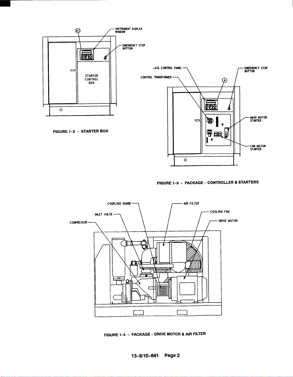
Starter Box . . . . . . . . . . . . . . . . . . . . . . . . . . . . . . . . . . . . . . . . . . . . . . . . . . . . . . . ., . . . ...2
Package -Controller&Starters . . . . . . . . . . . . . . . . . . . . . . . . . . . . . . . . . . . . . . . . . . ...2
Package -Drive Motor &Air Filter. . . . . . . . . . . . . . . . . . . . . . . . . . . . . . . . . . . . . . . . ...2
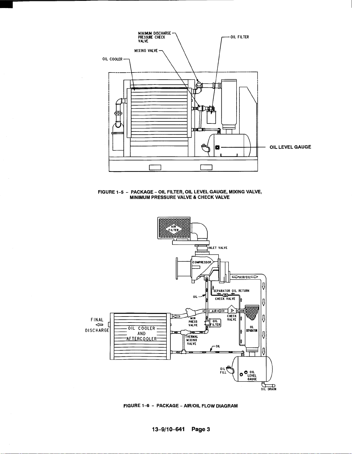
Package - Oil Filter, Oil Level Gauge, Mixing Valve, Minimum Pressure Valve
and Check Valve . . . . . . . . . . . . . . . . . . . . . . . . . . . . . . . . . . . . . . . . . . . . . . . . . . . . . . . . . .3
Package -Air/Oil Flow Diagram .,, . . . . . . . . . . . . . . . . . . . . . . . . . . . . . . . . . . . . . . . ...3
Typical Compressor Room . . . . . . . . . . . . . . . . . . . . . . . . . . . . . . . . . . . . . . . . . . . . . . . ...8
Air Flow Chart . . . . . . . . . . . . . . . . . . . . . . . . . . . . . . . . . . . . . . . . . . . . . . . . . . . . . . ...9
Cold Weather installation . . . . . . . . . . . . . . . . . . . . . . . . . . . . . . . . . ., . . . . . . . . . . . . ...10
inlet Line Lengths . . . . . . . . . . . . . . . . . . . . . . . . . . . . . . . . . . . . . . . . ., . . . . . . . . . . . . ...11
Heat Exchanger (Oil Cooler) Approximate Water Flow . . . . . . . . . . . . . . . . . . . . . . . . . 11
Aftercooler Approximate Water Flow . . . . . . . . . . . . . . . . . . . . . . . . .,, , . . . . . . . . . ...12
Series Piping . . . . . . . . . . . . . . . . . . . . . . . . . .. s. . . . . . . . . . . . . . . . . . . . . . . . . . . . . . ...13
Parallel Piping . . . . . . . . . . . . . . . . . . . . . . . . . . . . . . . . . . .’. . . . . . . . . . . . . . . . . . . . . . ...13
Auto Sentry-ES Display . . . . . . . . . . . . . . . . . . . . . . . . . . . . . . . . . . . . . . . . . . . . . . . . ...19
Schematic Tubing Diagram . . . . . . . . . . . . . . . . . . . . . . . . . . . . . . . . . . . . . . . . . . . . . ...27
Blowdown Valve . . . . . . . . . . . . . . . . . . . . . . . . . . . . . . . . . . . . . . . . . . . . . . . . . . . . . . . ...28
Minimum Discharge Pressure Valve . . . . . . . . . . . . . . . . . . . . . . . . . . . . . . . . . . . . . . ...28
Inlet Valve . . . . . . . . . . . . . . . . . . . . . . . . . . . . . . . . . . . . . . . . . . . . . . . . . . . . . . . . . . . ...29
Shuttle Valve . . . . . . . . . . . . . . . . . . . . . . . . . . . . . . . . . . . . . . . . . . . . . . ,,, . . . . . . . . . ...30
Turn Valve -Turn Valve Units Only . . . . . . . . . . . . . . . . . . . . . . . . . . . . . . . . . . . . . . . ...30
Control Schematic -Compressor Unloaded -Constant Speed Mode,
EBH&EBM Units Only . . . . . . . . . . . . . . . . . . . . . . . . . . . . . . . . . . . . . ., . . . . . . . . . . ...33
Control Schematic -Compressorat Full Load -Constant Speed Mode,
EBH&EBM Units Only .... . . . . . . . . . . . . . . . . . . . . . . . . . . . . . . . . . . . . . . . . . ...34
Control Schematic -Compressor Unloaded -LowDemand Mode orAuto Mode
EBH&EBM Units Only . . . . . . . . . . . . . . . . . . . . . . . . . . . . . . . . . . . . . . . . . . . . . . . . . ...35
Control Schematic-Compressor at Full Load, Turn Valve Units Only . . . . . . . . . . . . 36
Control Schematic -Compressor Fully Unload -Low Demand Mode Switch Off,
Turn Valve Units Only . . . . . . . . . . . . . . . . . . . . . . . . . . . . . . . . . . . . . . . . . . . . . . . . . . ...37
Control Schematic -Compressor Fully Loaded -Low Demand Mode Sw”tch On,
Turn Valve Units Only . . . . . . . . . . . . . . . . . . . . . . . . . . . . . . . . . . . . . . ., . . . . . . . . . . ...38
Wiring Diagram -207ECP546 . . . . . . . . . . . . . . . . . . . . . . . . . . . . . . . . . . . . . . . . . . ...39
Wiring Diagram -209ECP546 ... . . . . . . . . . . . . . . . . . . . . . . . . . . . . . . . , . . . . ...40
Wiring Diagram -202EAQ546 . . . . . . . . . . . . . . . . . . . . . . . . . . . . . . . , . . . . . . . . . ...41
Flow Diagram . . . . . . . . . . . . . . . . . . . . . . . . . . . . . . . . . . . . . . . . . . . . . . . . . . . . . . . . . ...43
Oil Flow Diagram -Remote Overhead Mounted . . . . . . . . . . . . . . . . . . . . . . . . . . . . . ,44
Cooler Drain Detail . . . . . . . . . . . . . . . . . . . . . . . . . . . . . . . . . . . . . . . . . . . . . . . . . . . . . ...45
Oil Level Gauge . . . . . . . . . . . . . . . . . . . . . . . . . . . . . . . . . . . . . . . . . . . .,, , . . . . . . . . ...47
Oil Change Interval . . . . . . . . . . . . . . . . . . . . . . . . . . . . . . . . . . . . . . . . . . . . . . . . . . . . ...47
Approximate Oil System Capacities . . . . . . . . . . . . . . . . . . . . . . . . . . . . . . . . . . . . . . ...48
Thermostatic Mixing Valve Element . . . . . . . . . . . . . . . . . . . . . . . . . . . . . . . . . . . . . . ...50
Water Control Valve.......,,, . . . . . . . . . . . . . . . . . . . . . . . . . . . . , . . . . . . . . . . . . . ...51
Dew Point Temperaturevs. Ambient Temperature, (100% Relative Humidity) . . . . . 51
Oil Separator . . . . . . . . . . . . . . . . . . . . . . . . . . . . . . . . . . . . . . . . . . . . . . . ., . . . . . . . . . ...52
Heavy Duty Air Filter (Standard), . . . . . . . . . . . . . . . . . . . . . . . . . . . . . . , . . . . . . . . . ...54
installation of Coupling Cushions . . . . . . . . . . . . . . . . . . . . . . . . . . . . . . . . . . . . . . . . ...56
13-9/10-841 Pageix

SECTION 1
GENERAL INFORMATION
FIGURE 1-1 - COMPRESSION CYCLE
COMPRESSOR - The Gardner Denver Rotary Screw
compressor is a single stage, positive displacement
rotary machine using meshing helical rotors to effect
compression. Both rotors are supported between high
capacity roller bearings located outside the compression chamber. Single width cylindrical roller bearings
are used at the inlet end of the rotors to carry part of the
radial loads. Tapered roller bearings at the discharge
end locate each rotor axially and carry all thrust loads
and the remainder of the radial loads.
COMPRESSION PRINCIPLE (FIGURE l-l) - Compression is accomplished by the main and secondaty
rotors synchronously meshing in a one-piece cylinder.
The main rotor has four (4) helical lobes 90° apart. The
secondary rotor has six (6) matching helical grooves
60° apart to allow meshing with main rotor lobes.
The air inlet port is located on top ofthe compressor cylinder near the drive shaft end. The discharge port is
near the bottom at the opposite end of the compressor
cylinder. Figure 1-1 is an invetted view to show inlet
and discharge ports. The compression cycle begins as
rotors unmesh at the inlet port and air is drawn into the
cavity between the main rotor lobes and secondary rotor grooves (A). When the rotors pass the inlet port cutoff, air istrapped in the interlobe cavity and flows axially
with the meshing rotors (B). As meshing continues,
more of the main rotor lobe enters the secondary rotor
grove, normal volume is reduced and pressure in-
creases.
Oil is injected into the cylinder to remove the heat of
compression and seal internal clearances. Volume reduction and pressure increase continues until the air/oil
mixture trapped in the interlobe cavity by the rotors
passes the discharge port and is released to the oil res-
v
v
ervoir (C). Each rotor cavity follows the same “fill–compress-discharge” cycle in rapid succession to produce
a discharge air flow that is continuous, smooth and
shock free.
AIR FLOW IN THE COMPRESSOR SYSTEM
(FIGURE 5-1, page 42) - Air enters the air filter and
passes through the inlet unloader valve to the compressor. After compression, the air/oii mixture passes
into the oil reservoir where most of the entrained oil is
removed by velocity change and impingement and
drops back into the reservoir. The air and remaining oil
passes into the separator and separator housing where
the oil is separated and passes through tubing connecting the separator housing and compressor. The air
passes through the minimum pressure valve, discharge check valve and cooler, then to the plant air
lines.
LUBRICATION, COOLING AND SEALING - Oil is
forced by air pressure from the oil reservoir through the
oil cooler, thermostatic mixing valve, and oil filter and
discharges into the compressor main oil gallery. A portion of the oil is directed through internal passages to
the bearings, gears and shaft oil seal. The balance of
the oil is injected directly into the compression chamber
to remove heat of compression, seal internal clearances and lubricate the rotors,
TURN VALVE (EAP UNITS ONLY) - The turn valve is
a rotary helical valve located on the discharge side of
the cylinder toward the inlet end, The valve opens and
closes ports in the cylinder which communicates with
the inlet passage. This varies the compressor rotor volume to match the demand for air, thus reducing the
part-load power requirement.
13-9/1 0-641
Page 1
EKRENCY STOP
rA’RF’LTERrc
SUTTON
FIGURE 1-2- STARTER BOX
LED. CONTROLPANEL~
TWSFORMER
CONTROL
FIGURE 1-3-
~ EMERGENCYSTOP
SLJTTON
~ FM MOTOR
o
PACXAGE - CONTROLLER & STARTERS
I
STARTER
COMPKSSOR
INLET VAVE ~
7
cOwL’N’G”MDl
\\
FIGURE 1-4- PACKAGE - DRIVE MOTOR & AIR FILTER
~lVE MOTOR
1/-
13-9/10-641 Page 2
1
MINIMUN OISCHARG[
PRESS~ CHECK
VALVE
OIL FILTER
r
\“’L::’:::L------L -------
o
1
I /
\
— OIL LEVEL GAUGE
FIGURE 1-5- PACKAGE - OIL FILTER, OIL LEVEL GAUGE, MIXING VALVE,
FINAL
-
DI
SCHAR
MINIMUM PRESSURE VALVE & CHECK VALVE
-NLETVAL’E
1
I
PRESS I
VALVE ‘
MIXINQ
VALVE
4
FIGURE 1-6 - PACKAGE - AIR/OIL FLOW DIAGRAM
13-9/1 0-641 Page 3

SAFETY PRECAUTIONS
Safety is everybody’s business and is based on your use of good common sense. All situations or circumstances
cannot always be predicted and covered by established rules. Therefore, use your past experience, watch out for
safety hazards and be cautious.
Some general safety precautions are given below:
~DANGER
Failure to observe these notices could result in injury to or death of personnel.
. Keep fingers and clothinq awav from revolving fan, drive coupling, etc.
● Donotuse the air discharge from this unit for breathing - not suitable for hu-
man consumption.
● Do not loosen or remove the oil filler plug, drain plugs, covers, the thermostat-
ic mixing valve or
tem until the unit is shut down and the air pressure
break any connections, etc., in the compressor air or oil sys-
has been relieved.
. Electrical shock can and may be fatal.
. Compressor unit must be carounded in accordance with the National Electrical
Code. Aground jumper equal to the size of the equipment ground conductor
must be used to connect the compressor motor base to the unit base.
. Fan motors must remain grounded to the main base through the starter
mounting panel in accordance with the National Electrical Code.
. Open main disconnect switch, tag and lockout before working on the control.
. Disconnect the compressor unit from its power source, tag and lockout be-
fore working on the unit
- this machine is automatically controlled and may
start at any time.
13-9/1 0-641 Page 4

WARNING
Failure to observe these notices could result in damage to equipment.
●
Stop the unit if any repairs or adjustments on or around the compressor are
required.
●
Disconnect the compressor unit from its power source, tag and lockout before working on the unit
start at any time.
●
An Excess Flow Valve should be on all compressed air supply hoses exceeding 1/2 inch inside diameter. (OSHA Regulation, Section 1926.302)
●
Do not exceed the rated maximum Pressure values shown on the nameplate.
●
Do not operate unit if safety devices are not operating properly. Check periodically. Never bypass safety devices.
- this machine is automatically controlled and may
13-9/10-641 Page 5
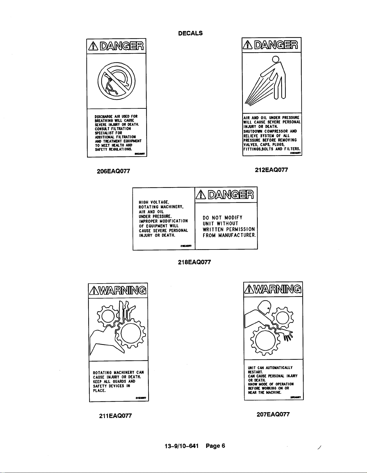
DECALS
DISCHARGEAIR USED FOR
BREATHINGWILL CAUSE
SEVERE INJURY ORDEATH.
CONSULTFILTRATION
SPECIALIST FOR
ADDITIONALFILTRATION
ANDTREATMENT EQUIPNENT
TO MEET HEALTH AND
SAFETY REGULATIONS.
206EAQ077
HIGH VOLTAGE,
ROTATING MACHINERY.
AIR AND OIL
UNDER PRESSURE.
IMPROPER MODIFICATION
OF EQUIPMENT WILL
CAUSE SEVERE PERSONAL
INJURY OR DEATH.
t-
218EAQ077
DO NOT MODIFY
UNIT WITHOUT
WRITTENPERMISSION
FROMMANUFACTURER.
T
1
AIR AND OIL UNDER PRESSURE
WILL CAUSE SEVERE PERSONA
INJURY OR DEATH.
SHUTDOWNCOMPRESSORAND
RELIEVE
SYSTEMOF ALL
PRESSUREBEFOREREMOVING
VALVES.CAPS,PLUGS,
FITTINGS, BOLTSANDFILTERS
-
212 EAQ077
ROTATING MACHINERY CAN
CAUSE INJURY OR DEATH.
KEEP ALL GUARDSAND
SAFETY DEVICES IN
PLACE.
211 EAQ077
13-9/10-641 Page 6
UNIT CANAUTOMATICALLY
RESTART.
CANCAUSEPERSONALINJURY
ORDEATH.
KNOWMODEOF OPERATION
BEFOREWORKINGON OR
NEARTHE MACHINE.
—
207 EAQ077
/’

ELECTRICAL SHOCK FROM
IMPROPER GROUNDING CAN
CAUSE INJURY OR DEATH.
GROUND UNIT AND RELATED
EQUIPMENT ACCORDING TO
NATIONAL ELECTRIC CODE
AND LOCAL REGULATIONS.
AIR AND OIL UNDER
PRESSURE.
CAN CAUSE SEVERE
PERSONAL INJURY
OR DEATH.
INSPECT OIL RESERVOIR
FOR CRACKS AT LEAST
ANNUALLY.
n-
216EAQ077
WARNING
DECALS
1 I
ELECTRICAL SHOCK CAN
CAUSE INJURY OR DEATH.
DISCONNECT ALL CIRCUITS
BEFORE WORKINQON THIS
CONTROL.
SEE WIRING DIAGRAM.
222EAQ077
217EAQ077
ELECTRICAL ARCING CAN
CAUSE A FIRE WHEN UNIT IS
MOUNTED ON A COMBUSTIBLE
SURFACE RESULTING IN
PERSONAL INJURY OR
PROPERTY OAMAGE.
UNIT MUST BE MOUNTEOON
A FLOOR PLATE EXTENDING
ON ALL SIDES.
SEE INSTALLATION
DRAWINGFOR PROPER
DIMENSIONS.
221EAQ077
@
MACHINE OAMAGEOR INJURY
CAN OCCURDUE TO IMPROPER
LIFTING.
DO NOT LIFT MACHINE WITH
THE MOTOR EYEBOLT.
208EAQ077
13-9/10-641 Page7

SECTION 2
INSTALLATION
GENERAL - On receipt of the unit, check for any damage that may have been incurred during transit. Report
any damage or missing parts as soon as possible.
~CAUTION
Do not electric weld on the compressor or base; bearings can be damaged
by passage of current.
LIFTING UNIT - Proper lifting and/or transporting
methods must be used to prevent damage. Lifting slotS
are provided in the base for towmotor use. The unitmay
also be moved into location by rolling on bars. -
~CAUTION
Lift compressor unit by base only. Do
not use other places such as motor,
compressor or discharge manifold
piping as lifting points.
~DANGER
The eyebolts or lugs provided on the
motor are for lifting the motor only
and should not be used to lift any
additional weight. All eyebolts must
be securely tightened. When lifting
the motor the lifting angle must not
exceed 15 degrees. Failure to observe
this warning may result in damage to
equipment or personal injury.
LOCATION - The compressor should be installed,
whenever possible, in a clean, well-lighted, well–venti-
Iated area with ample space all around for maintenance. Select a location that provides a cool, clean, dry
source of air. In some cases it may be necessary to
install the air filter at some distance from the compres-
sor to obtain proper air supply.
Both the air-cooled and water-cooled units require
cooling air as well as air to the compressor inlet. Proper
ventilation MUST be provided; hot air must be exhausted from the compressor operating area. Atypical
inlet–outlet air flow arrangement is shown in
FIGURE 2-1,
Air-Cooled Units - A combination oil/aftercooler is
supplied as standard equipment on all air-cooled units.
The air-cooled unit with the standard enclosure requires sufficient flow, FIGURE 2-2, page 9, for the
compressor oil/aftercooling system and for electric mo-
tor cooling. Air is drawn into the unit at the motor side
of the enclosure and is exhausted at the oil cooler side.
Do not block the air flow to and from the unit. Allow
three and one-half (3-1/2) feet (1. 1 M) to the nearest
obstruction on the starter end and control box end of
the unit. Allow three (3) feet (.9 M) to the nearest obstruction above and on other sides of unit. For continuous efficiency, oil cooler cores must be periodically
cleaned with either vacuum or compressed air. If wet
cleaning is required, shield motor and spray on a mild
soap solution and flush with clean water.
LO UVERFD
WINDOW WINDOW
/
EXHAUST FAN
LOUVERED
\
~DANGER
Compressor, air/oil reservoir, separa-
tion chamber and all piping and tub-
ing may beat high temperature during
and after operation.
13-9/10-641 Page 8
A75119
FIGURE 2-1 - TYPICAL COMPRESSOR ROOM

Minimum Air Flow * For Compression
And Cooling - Cubic Feet/Minute
(Cubic Meters/Minute)
HP (KW)
I
40& 50 HP
60-100 HP 12,500
(45-75 Kw)
* 80° F (27° C) Inlet Air
I Air Cooled ] Water Cooled I
6,500 1,400
1,700
(354)
(48)
~CAUTION
If the compressor unit base is raised
above floor level, the space between
the floor and the base bottom must be
closed with solid material all around
to prevent recirculation of hot air from
the oil cooler end and over temperature operation.
FIGURE 2-2 - AIR FLOW CHART
~wARNING
For aluminum oil coolers, do not use
any cleaning solution that is not compatible with aluminum. Use of improper solution may result in damage to
the cooler.
Water-Cooled Units - The water-cooled unit with the
standard enclosure requires sufficient air flow,
FIGURE 2-2, for electric motor cooling. Air is drawn
intothe unit at the top of the enclosure and is exhausted
at the motor side, Do not block airflow to and from unit.
Allow three and one-half (3-1/2) feet (1.1 M) to the
nearest obstruction on the starter end and control box
side of the unit. Allow three (3) feet (.9 M) to the nearest
obstruction above and on other sides of the unit.
FOUNDATION - The G-D Rotary Screw compressor
requires no special foundation, but should be mounted
on a smooth, solid surface. Whenever possible install
the unit near level. Temporary installation may be made
at a maximum 10° angle lengthwise or 10° sidewise.
Mounting bolts are not normally required. However,
installation conditions such as piping rigidity, angle of
tilt, or danger of shifting from outside vibration or moving vehicles may require the use of mounting bolts and
shims to provide uniform support for the base.
OIL RESERVOIR DRAIN - The oil drain is piped from
the bottom of the reservoir to the side of the frame. This
drain is approximately 4.50 inches(115 mm) above the
floor level, If this is not sufficient to conveniently drain
the oil some other methods of providing drain are:
1.
Elevate the compressor unit on a suitable struc-
ture to obtain the desired drain height.
2.
Construct an oil sump or trough below the floor
level and pump or bail the drained oil.
3. Pump oil from the reservoir filler opening or drain
to a container.
ENCLOSURE - The compressor, electric motor, oil
cooler and aftercooler are mounted inside the enclosure. Service doors are provided for maintenance access. Be sure to allow enough space around the unit
for the doors to open completely. Any of the enclosure
doors may be removed by opening the door and lifting
it up slightly to disengage the hinges.
I
~DANGER
Do not operate the compressor with
the fan and coupling guard removed.
Exposed fan and belts may cause
injury to personnel.
The motor inspection/air filter service panel is held by
two latches and lifts away from the enclosure, The air
outlet panel is attached by screws to the enclosure and
is not readily removable.
INSTALLATION FOR COLD WEATHER OPERA-
TION (FIGURE 2-3, page 10) - It is recommended
that the unit be installed inside a shelter that will be
heated to temperatures above freezing (32° F, O°C).
This will eliminate many of the problems associated
with operating units in cold climates where freezing
rain, drifting snow, freezing condensate and bitter cold
temperatures are encountered.
Refer to Engineering Data Sheet 13-9-411 for the advantages of using the heat recovered from rotary compressors. This heat recovery could easily pay for an adequate shelter for the unit,
When an outside installation must be made, the precautions required will depend on the severity of the environment. The following are general guidelines for
outside installations:
13-9/10-841 Page 9

@FT PLWOW FENCC
(2.4 M)
~LLMffl wlANT 2+LEMEN1
tEATER (OR EcUAL)
RH400 WITH ~ RH4~
ELEMENTS - Z SfOD
3200 wATTS EACH
WLLMN WINT 2-ELEMENT
HLATER (OR EOUAL)
RH7~ WITH 121 RH7W
ELWEN1.S -2 REOD
6ZC4 WATTS EACH
4
/“
LJ
3 FT
MOTOR
,m
‘\
AWAY FROM PREVAIL ING WIND
\ _COMPKSS~
+“ 4
FIGURE 2-3- COLD WEATHER INSTALLATION
Cold Weather (Down To +IO” F, -12°C)
1.
Be sure all drains, traps, and control lines, including pressure transducer lines are heated to avoid
freezing of condensate. Heat tape with thermostat control is generally satisfactory for this purpose and can be obtained at various local plumbing or hardware outlets at nominal cost.
2.
If an air-cooled aftercooler is to be used, provisions to bypass the aftercooler must be made.
Since cold air contains very little moisture, successful operation can be achieved without the af-
tercooler.
3.
Provide at least some simple shelter such as a ply-
wood windbreak to protect against drifting snow.
4,
Use only Gardner Denver@ AEON 9000 SP lu-
bricant.
Monitor the unit carefully during start-up and op-
5,
eration to be sure it is functioning normally.
6.
Specify NEMA 4 enclosure for electrical devices.
Extreme Cold Weather Operation (Down To -40° F,
-40° c)
In addition to the above, the following should be pro-
vided:
1.
It will be necessary to provide shutters or to block
off part of the cooler in some manner since the
cooler is greatly oversized for operation in these
low temperatures. Since shutters are not provided as a factory option, blocking off a portion of
the cooler with plywood should be satisfactory.
8 FT. (2.4M)
PLYWOOD ““F ENCEoo
4 FT.
~’(1.2M)
ELEVATION VIEW
Auto operation should not be used in extreme en-
2.
vironments.
Some means of providing heat during shutdown
3.
should be provided. There are various methods
to accomplish this, but since openings are not provided for sump heaters, the use of radiant heaters
is recommended, The heaters should be sized to
provide at leasta+1O”F(-12°C) environment for
coolers, motor and sump. FIGURE 2-3, page 10,
shows how these might be located in a typical
installation and sizes required.
Remember unsheltered (outside) installations should
be avoided where possible. Installation next to a
heated building where enough heat can be used to
keep the compressor room above freezing will save
many complications in the operation and installation of
the unit.
Refer to Engineering Data Sheet 13-9-411, available
from an authorized Gardner Denver distributor, for the
advantages of using the heat recovered from rotary
compressors. This heat recovery could easily pay for
an adequate shelter for the unit.
AUXILIARY AIR RECEIVER - An auxiliary air receiver
is notrequired ifthe piping system is large and provides
sufficient storage capacity to prevent rapid cycling.
When used, an air receiver should be of adequate size,
provided with a relief valve of proper setting, a pressure
gauge and a means of draining condensate. A means
of draining condensate will need to be provided for.
MOISTURE SEPARATOR/TRAP - Since the unit is
equipped with a built–in aftercooler, a combination
moisture separator and trap is furnished with the unit.
13-9/10-641 Page 10
Length of Inlet Line
Diameter of Pipe Size
OtolOFeet (Oto3 Meters) . . . . . . . . . . . . . . . . . . . . . . . . . . . . . . . . . . .
10 to 17 Feet (3 t05 Meters) . . . . . . . . . . . . . . . . . . . . . . . . . . . . . . . . . . One Size LargerThan Inlet Opening
17 t038Feet (5 toll,5 Meters). . . . . . . . . . . . . . . . . . . . . . . . . . . . . .
FIGURE 2-4 - INLET LINE LENGTHS
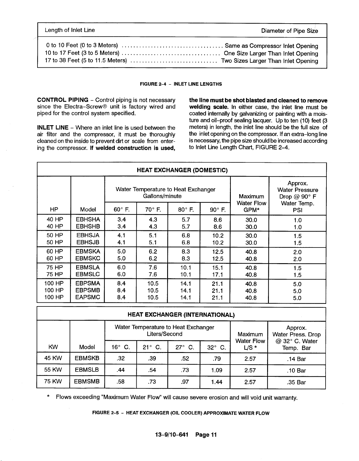
CONTROL PIPING - Control piping is not necessary
since the Electra–Screw@ unit is factory wired and
piped for the control system specified.
INLET LINE - Where an inlet line is used between the
air filter and the compressor, it must be thoroughly
cleaned on the inside to prevent dirtor scale from enter-
ing the compressor. If welded construction is used,
HEAT EXCHANGER (DOMESTIC)
Water Temperature to Heat Exchanger
HP
Model
the line must be shot blasted and cleaned to remove
welding scale. In either case, the inlet line must be
coated internally by galvanizing or painting with a moisture and oil-proof sealing lacquer, Up to ten (1O)feet (3
meters) in length, the inlet line should be the full size of
the inletopening on the compressor. If an extra-long line
isnecessary, the pipe size should be increased according
to Inlet Line Length Chart, FIGURE 2-4,
Same as Compressor Inlet Opening
Two Sizes Larger Than Inlet Opening
Approx.
Water Pressure
Drop @ 90° F
Water Temp.
Psl
40 HP
40 HP
50 HP
50 HP
60 HP
60 HP
75 HP
75 HP
100 HP
100 HP
100 HP
Kw
45 Kw
55 Kw
75 Kw
EBHSHA
EBHSHB
EBHSJA
EBHSJB
EBMSKA
EBMSKC
EBMSLA
EBMSLC
EBPSMA
EBPSMB
EAPSMC
Model 16° C. 21° c. 27° C,
EBMSKB
EBMSLB .44 .54
EBMSMB
3.4 I 4.3 I 5.7 I 8.6 I 30.0
3.4
4.1
4.1 5,1
5.0
5.0 6.2
6,0 7,6
6.0 7,6
8.4 10.5
8.4 10.5
8,4 10,5
HEAT EXCHANGER (INTERNATIONAL)
Water Temperature to Heat Exchanger
.32 .39
.58
4.3
I
5,1
I
6.2
I
Liters/Second Maximum
.73 .97
I
I
5.7
6.8
6.8
8.3
8.3
10.1
10,1
14.1
14.1
14.1
.52
.73
8.6
I
10.2
10.2 30.0
I
12.5
I
12.5 40.8
15.1 40.8
17.1
21.1 40.8
21.1 40.8
21.1 40,8
32° C. L/s * Temp. Bar
.79 2,57 .14 Bar
1.09 2.57 .10 Bar
1.44 2.57 .35 Bar
30.0
I
30.0
I
,
40.8
I
40.8
Water Flow
Approx.
Water Press. Drop
@ 32° C. Water
1.0
1.0
1,5
1.5
2.0
2.0
1.5
1.5
5.0
5.0
5.0
* Flows exceeding “Maximum Water FIow" will cause severe erosion and will void unit warranty.
FIGURE 2-5- HEAT EXCHANGER (OIL COOLER) APPROXIMATE WATER FLOW
13-9/1 0-641 Page 11

AFTERCOOLER (DOMESTIC)
I I
Water Temperature to Heat Exchanger
Gallons/minute
HP Model 600 F.
40 HP EBHSHA
40 HP
50 HP EBHSJA .7 .9
50 HP EBHSJB .7 .9 1.2
60 HP
60 HP
75 HP EBMSIA 1.2
75 HP EBMSLC
100 HP EBPSMA 1.7 2.1 2.8
100 HP EBPSMB 1.7
100 HP EAPSMC 1.7
Kw Model 16° C.
EBHSHB .5 .7 .9
EBMSKA
EBMSKC .8 1.0 1.4
.5 .7 .9 1.3
.8
1.2
Water Temperature to Heat Exchanger
70° F. 80° F, 90° F.
1.2 1.8
1.0 1.4
1,5 2.0 3.0
1.5 2.0
2.1 2.8
2.1 2.8 4.1
AFTERCOOLER (INTERNATIONAL)
Liters/Second
210 c. 27° C.
Maximum
Water Flow
GPM*
26.0
1,3
1.8
2.1
2.1
3.0
4.1
4.1
32° C. L/s *
26.0
26.0
26.0
26.0
26.0
26.0
3
26.0
26.0
26.0
26.0
Maximum
Water Flow
Approx.
Water Pressure
Drop @ 90° F
Water Temp.
Psl
Less than 1 PSI
for any flow rate
shown in the table.
I
Approx.
Water Press. Drop
@ 32° C. Water
Temp. Bar
45 Kw EBMSKB .05 ,06 .09
55 Kw EBMSLB ,08 .09 ,13
75 Kw EBMSMB .11 .13 .18
* Flows exceeding “Maximum Water Flow" will cause severe erosion and will void unit warranty,
FIGURE 2-6- AFTERCOOLER APPROXIMATE WATER FLOW
Accessibility for inlet air filter servicing must be considered when relocating the filters from the unit to a remote
location,
DISCHARGE SERVICE LINE - The discharge service
line connection on both water-cooled and air-cooled
units is made at the right hand corner of the unit, viewed
from the opposite end from control panel side. When
manifolding two or more rotary screw units on the same
line, each unit is isolated by the check valve in the unit
discharge line. If a rotary screw unit is manifolded to
another compressor, be sure the other compressor has
a check valve in the line between the machine and the
manifold. If a rotary screw and a reciprocating compressor are manifolded together, an air receiver must
be located between the two units. Iation requires, the muffler may be removed and the
I
Discharge air used for breathing will
cause severe injury or death.
Consult filtration specialists for addi-
tional filtration and treatment equip-
ment to meet health and safety standards.
BLOWDOWN VALVE PIPING - The blowdown valve
isfitted with a muffler for operation indoors. Ifthe instal-
.13
.19
.26
1.64
1.64
1.64
~DANGER
Less than .1 Bar
for any flow rate
shown in the table.
13-9/10-641 Page 12

OILWT
OILIN
C76683
THERMOSTATIC
~
MIXING WLVE
4------------4~ -----
tiEAT EXCHAMER
I
I
AIR
IN
* (OPTIONAL) WATER CONTROL VALVE AND WATER
FIGURE 2-7 - SERIES PIPING
blowdown valve piped to the outside with a pipe size the
same as the blowdown valve outlet connection.
WATER PIPING (Water-Cooled Heat Exchanger
Models Only) - On machines equipped with watercooled heat exchangers, the water inlet and outlet connections are located in the unit base flange on the left
side of the unit.
T
*WATER CmTROL
VATER WOFF WLVE
L
WATER
OUT
WVE
C76682
~wATER C~TROL VALVE
WATER ~UTOFF WLVE
‘wATE R
HEAT ExCJiAffiER
WAT EQ
CUT
L
***~.T,.c::v
I
AlR
IN
SHUTOFF VALVE MUST BE ORDERED SEPARATELY,
FIGURE 2-8 - PARALLEL PIPING
(43° C). If water cooler than 60° F is used, high water
outlet temperatures (over 110° F, 43° C) will be experienced along with shortened heat exchanger life caused
bytube fouling and corrosion. Ifwater warmer than 90°
F (32° C) is used, higher compressor oil inlet temperatures and high water usage will result.
Most water systems will require control of impurities:
filtration, softening or other treatment. See “Compressor Oil Cooler - Water-Cooled Heat Exchanger” for
more information on the water system.
~:~?
‘&SEPARATOR/TRAP
~WARNING
It is mandatory that any water cooled
unit be installed in a shelter heated to
temperatures above freezing (32° F.,
0°c).
The water source should be capable of supplying up to
the maximum flow shown in FIGURE 2-5, page 11,
and FIGURE 2-6, page 12, at a minimum pressure of
40 psig (2.8 Bars); maximum allowable water pressure
is 150 psig (10.3 Bars). The water flow rates shown are
approximate and a guide to sizing piping, cooling tower
and other water system equipment.
The heat exchanger system is designed to operate with
water inlet temperatures from 60° to 90° F (16° to 32°
C) and a water outlet temperature not to exceed 11O°F
13-9/10-841 Page 13
SERIES PIPING (FIGURE 2-7) - Water flow must be
through aftercooler first for effective cooling of discharge air and is so piped on the standard watercooled unit.
PARALLEL PIPING (FIGURE 2-8) - A separate water control valve is required to control the discharge air
temperature. If a remote (externally mounted) watercooled aftercooler is piped in parallel with the heat exchanger, provide a separate water control valve for the
aftercooler and pipe separate inlet water lines to both
the aftercooler and heat exchanger,
The water control valve isto be adjusted to maintain oil
out of the heat exchanger within the 140° to 150° F
(60° to 66° C) range regardless of inlet water flow or
temperature as long as a minimum flow for a given temperature is met (FIGURE 2-5, page 11, and
FIGURE 2-6, page 12. See Section 5, page 41, for ad-

justment instructions and maximum allowable lubricant
temperature.
~wARNING
ELECTRICAL WIRING - Standard Units - The Elec-
tra-Saver@ compressor is factory wired for all starter
to motor and control connections for the voltage specified on the order. It is necessary only to connect the unit
starter to the correct power supply. The standard unit
is supplied with an open drip-proof motor, a NEMA 12
starter and control enclosure. See “Location” para-
graph, page 8, for distance to the nearest obstruction
on starter and control box sides of the unit.
Lower operating voltages (200/208) require that the
unit starter be remote mounted since the starter is too
large to be mounted within the control enclosure. If not
supplied with the compressor unit, the starter is to be
a size 6 full voltage non-reversing type in NEMA
(CEMA) enclosure suitable for the environment, with
two (2) rejection type control circuit fuses (size accord-
ing to motor starter manufacturer’s standard), a 200
(208) volt coil, and three (3) overload heaters for 200
(208) volt 100 HP (75 KW), 1.15 service factor motor.
The overload heaters are to be selected according to
starter manufacturer’s tables based on motor nameplate full load amperage.
Failure to properly ground the compressor package could result in con-
troller malfunction.
MOTOR LUBRICATION - Long time satisfactory operation of an electric motor depends in large measure
on proper lubrication of the bearings. The following
charts show recommended grease qualities and regressing intervals for ball bearing motors. For additional information refer to the motor manufacturer’s
instructions. The following procedure should be used
in regressing:
1.
Stop the unit.
2.
Disconnect, tag and lockout the unitfrom the power supply.
3.
Remove the relief plug and free hole of hardened
grease.
4.
Wipe lubrication fitting clean and add grease with
a hand-operated grease gun, Only enough
grease should be added to replace the grease
used by the bearing. Too much grease can be as
harmfull as insufficient grease. The grease cavity
should be about 1/2 full.
~wARNING
Electrical shock can cause injury or
death. Open main disconnect switch,
tag and lockout before working on
starter/control box.
GROUNDING - Equipment must be grounded in accordance with Table 250-95 of the National Electrical
Code.
5.
Leave the relief plug temporarily off. Reconnect
the unit and run for about 20 minutes to expell the
excess grease.
6.
Stop the unit. Replace the relief plug,
7.
Restart the unit.
~wARNING
Rotating machinery can cause injury
or death. Open main disconnect, tag
and lockout power supply to the starter
before working on the electric motor.
13-9/10-841 Page 14

ELECTRIC MOTOR GREASE RECOMMENDATIONS (-30° to 50° C)
Type of Service
Standard
MANUFACTURER
CHEVRON
SHELL
EXXON
EXXON
ELECTRIC MOTOR REGRESSING INTERVAL
Typical Examples
One- or Two-Shift Operation
I
150 HP(112KW)
Above 150 HP (112 KW)
TRADE NAME
SRI #2
DOLIUM R
UNIREX #2
POLYREX
Rating
Relubrication
Interval
18 Months
12 Months
Severe
Very Severe Dirty Locations, High
Continuous Operation
Ambient Temperature
1
150 HP(112KW)
Above 150 HP (112 KW)
150HP (112 KW)
Above 150 HP (112 KW)
I
9 Months
6 Months
4 Months
2 Months
I
13-9/10-841 Page 15
SECTION 3
STARTING & OPERATING PROCEDURES
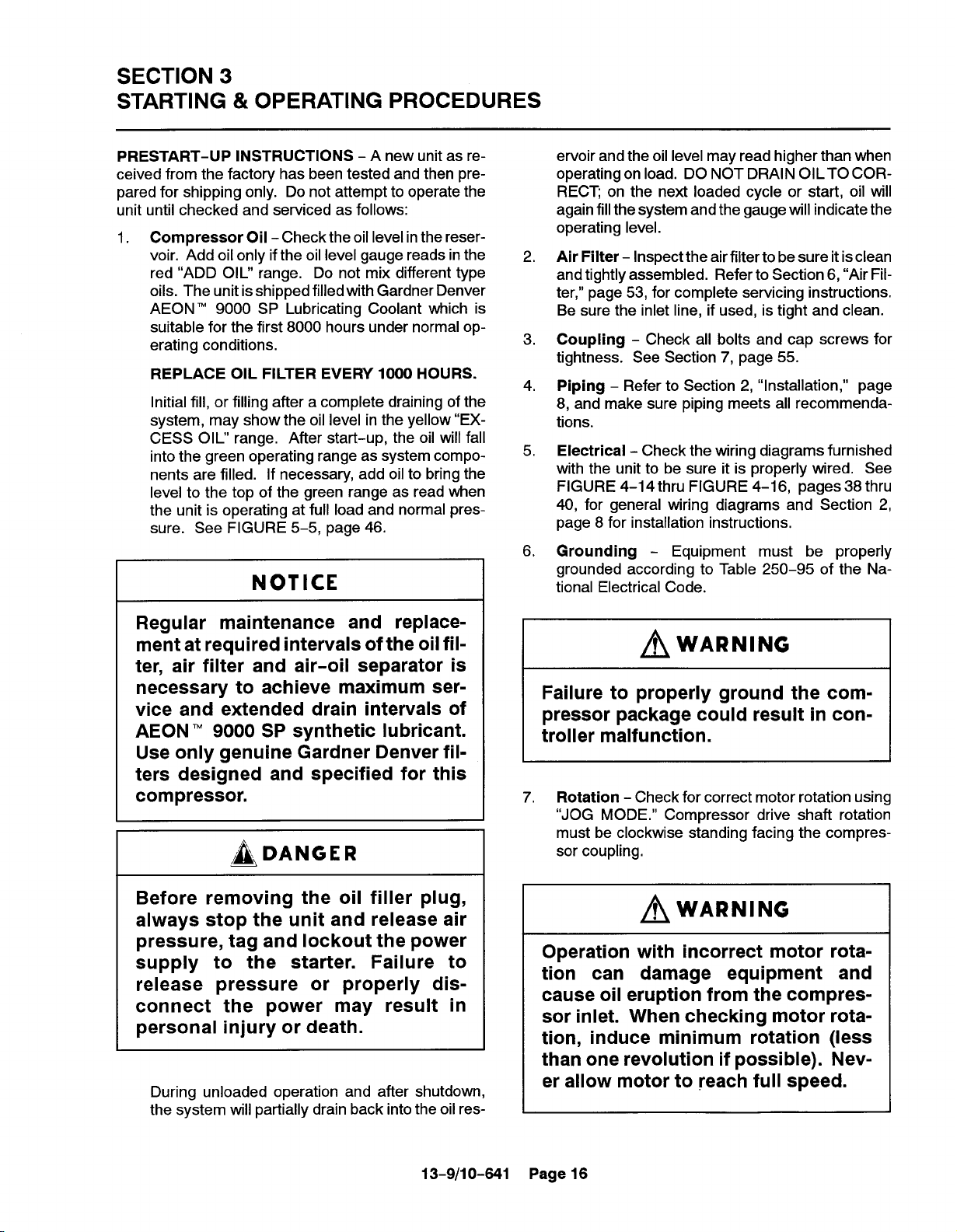
PRESTART-UP INSTRUCTIONS - A new unit as re-
ceived from the factory has been tested and then pre-
pared for shipping only. Do not attempt to operate the
unit until checked and serviced as follows:
1. Compressor Oil - Check the oil level inthe reservoir. Add oil only ifthe oil level gauge reads in the
red “ADD OIL” range. Do not mix different type
oils. The unit is shipped filled with Gardner Denver
AEON 9000 SP Lubricating Coolant which is
suitable for the first 8000 hours under normal operating conditions.
REPLACE OIL FILTER EVERY 1000 HOURS.
Initial fill, or filling after a complete draining of the
system, may show the oil level in the yellow “EXCESS OIL” range. After start-up, the oil will fall
into the green operating range as system components are filled. If necessary, add oil to bring the
level to the top of the green range as read when
the unit is operating at full load and normal pres-
sure. See FIGURE 5–5, page 46.
NOTICE
ervoir and the oil level may read higher than when
operating on load. DO NOT DRAIN OIL TO CORRECT; on the next loaded cycle or start, oil will
again fillthe system and the gauge will indicate the
operating level.
2. Air Filter - Inspect the air filter to be sure it is clean
and tightly assembled. Refer to Section 6, “Air Filter,” page 53, for complete servicing instructions.
Be sure the inlet line, if used, is tight and clean.
3. Coupling - Check all bolts and cap screws for
tightness. See Section 7, page 55.
4. Piping - Refer to Section 2, “installation,” page
8, and make sure piping meets all recommendations.
5, Electrical - Check the wiring diagrams furnished
with the unit to be sure it is properly wired. See
FIGURE 4-14thru FIGURE 4-16, pages 38 thru
40, for general wiring diagrams and Section 2,
page 8 for installation instructions,
6. Grounding - Equipment must be properly
grounded according to Table 250-95 of the National Electrical Code.
Regular maintenance and replacement at required intervals of the oil fil-
ter, air filter and air-oil separator is
necessary to achieve maximum service and extended drain intervals of
AEON ‘M9000 SP synthetic lubricant.
Use only genuine Gardner Denver filters designed and specified for this
compressor.
DANGER
Before removing the oil filler plug,
always stop the unit and release air
pressure, tag and lockout the power
supply to the starter. Failure to
release pressure or properly dis-
connect the power may result in
personal injury or death.
During unloaded operation and after shutdown,
the system will partially drain back into the oil res-
~wARNING
Failure to properly ground the compressor package could result in con-
troller malfunction.
7. Rotation - Check for correct motor rotation using
“JOG MODE.” Compressor drive shaft rotation
must be clockwise standing facing the compressor coupling,
~wARNING
Operation with incorrect motor rota-
tion can damage equipment and
cause oil eruption from the compres-
sor inlet. When checking motor rotation, induce minimum rotation (less
than one revolution if possible). Nev-
er allow motor to reach full speed.
13-9/1
0-641
Page 16

8. System Pressure - Set the controls to the desired load pressure. DO NOT EXCEED THE
MAXIMUM OPERATING PRESSURE ON THE
COMPRESSOR NAMEPLATE. See Section 4,
“Controls and Instruments” for procedure.
~WARNING
Operation at excessive discharge air
pressure can cause personal injury or
damage to equipment. Do not adjust
the full discharge air pressure above
the maximum stamped on the unit
nameplate.
Check all screws and latches for tightness. Be
sure doors are closed and latched.
STARTING THE UNIT - Observe the following starting
procedures.
Unit Cold - If the unit is a water-cooled heat exchanger model, open any manual water inlet valves wide
open. Start the unit by pushing either the “CONSTANT
RUN” button or one of the “AUTO” buttons. Since the
unit is equipped with a minimum (65 psig, 4.5 Bars)
pressure discharge valve, no special procedure to
maintain unit reservoir pressure is required.
Unit Hot - No warm-up period is required. If the unit
is a water-cooled heat exchanger model, open any
manual water inlet valves wide open. Start the unit by
pushing either the ‘(CONSTANT RUN” button or one of
the “AUTO buttons.
DAILY CHECK - Refer to Section 8, ‘iMaintenance
Schedule,” page 56.
Operating Mode - Refer to Section 4 for detailed
9.
information on the control system.
Enclosure - Check for damaged panels or doors.
10.
STOPPING THE UNIT - Press “STOP-RESET” button. The oil reservoir will automatically blow down as
the motor stops. If the unit is a water-cooled heat exchanger type, close any manual water inlet valves.
13-9/10-641 Page 17
SECTION 4
CONTROLS & INSTRUMENTATION
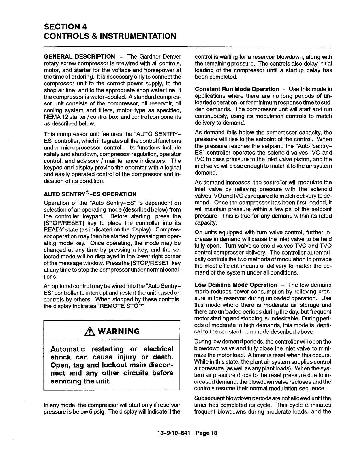
GENERAL DESCRIPTION - The Gardner Denver
rotary screw compressor is prewired with all controls,
motor, and starter for the voltage and horsepower at
the time of ordering. It is necessary only to connect the
compressor unit to the correct power supply, to the
shop air line, and to the appropriate shop water line, if
the compressor is water-cooled. A standard compressor unit consists of the compressor, oil reservoir, oil
cooling system and filters, motor type as specified,
NEMA 12 starter /control box, and control components
as described below.
This compressor unit features the “AUTO SENTRY-
ES controller, which integrates allthe control functions
under microprocessor control. Its functions include
safety and shutdown, compressor regulation, operator
control, and advisory / maintenance indicators. The
keypad and display provide the operator with a logical
and easily operated control of the compressor and indication of its condition.
AUTO SENTRY'-ES OPERATION
Operation of the “Auto Sentry-ES’ is dependent on
selection of an operating mode (described below) from
the controller keypad.
[STOP/RESET] key to place the controller into its
READY state (as indicated on the display). Compressor operation may then be started by pressing an operating mode key. Once operating, the mode may be
changed at any time by pressing a key, and the se-
lected mode will be displayed in the lower right corner
ofthe message window. Press the [STOP/RESET] key
at anytime to stop the compressor under normal conditions,
An optional control maybe wired into the “Auto Sentry-
ES controller to interrupt and restart the unit based on
controls by others. When stopped by these controls,
the display indicates “REMOTE STOP”.
Before starting, press the
~WARNING
Automatic restarting or electrical
shock can cause injury or death.
Open, tag and lockout main disconnect and any other circuits before
servicing the unit.
control is waiting for a reservoir blowdown, along with
the remaining pressure, The controls also delay initial
loading of the compressor until a startup delay has
been completed.
Constant Run Mode Operation - Use this mode in
applications where there are no long periods of unloaded operation, orfor minimum response time to sudden demands. The compressor unit will start and run
continuously, using its modulation controls to match
delivery to demand.
As demand falls below the compressor capacity, the
pressure will rise to the setpoint of the control. When
the pressure reaches the setpoint, the “Auto Sentry-
ES controller operates the solenoid valves IVO and
IVC to pass pressure to the inlet valve piston, and the
inlet valve willclose enough to match itto the air system
demand.
As demand increases, the controller will modulate the
inlet valve by relieving pressure with the solenoid
valves IVO and IVC as required to match delivery to demand. Once the compressor has been first loaded, it
will maintain pressure within a few psi of the setpoint
pressure. This is true for any demand within its rated
capacity.
On units equipped with turn valve control, further increase in demand will cause the inlet valve to be held
fully open. Turn valve solenoid valves TVC and TVO
control compressor delivery. The controller automatically controls the two methods of modulation to provide
the most efficient means of delivery to match the demand of the system under all conditions.
Low Demand Mode Operation - The low demand
mode reduces power consumption by relieving pressure in the reservoir during unloaded operation. Use
this mode where there is moderate air storage and
there are unloaded periods during the day, but frequent
motor starting and stopping is undesirable. During peri-
ods of moderate to high demands, this mode is identical to the constant-run mode described above.
During Iowdemand periods, the controller will open the
blowdown valve and fully close the inlet valve to minimize the motor load. A timer is reset when this occurs.
While inthis state, the plant air system supplies control
air pressure (as well as any plant loads). When the system air pressure drops to the reset pressure due to increased demand, the blowdown valve recloses and the
controls resume their normal modulation sequence.
In any mode, the compressor will start only if reservoir
pressure is below5 psig. The display will indicate ifthe
13-9/1
0-641
Subsequent blowdown periods are not allowed untilthe
timer has completed its cycle. This cycle eliminates
frequent blowdowns during moderate loads, and the
Page 18

energy required to re pressurize the reservoir. It also
eliminates the problems of oil foaming and carryover
that can occur if the oil reservoir of an oil-flooded com-
pressor is blown down too often. The timer is adjust-
able from 5 to 20 minutes.
Automatic Mode Operation - This mode provides
automatic start and timed stop, and is best used in applications with long unloaded periods and adequate
storage to allow stopping the compressor for periods.
Operation during periods of moderate to heavy demands is identical to the low demand mode described
above.
The automatic time delay is adjustable from 5 to 20
minutes. Ifthe controller operates unloaded for this period with no demand, the compressor drive motor is
halted to eliminate its power consumption. The controls will remain in this state until demand is again indicated by a drop in pressure.
Sequence Mode Operation - This mode provides for
communication between controllers, operating only as
many as are required for economical operation. Use
this on applications with large storage capacity and diverse loads. The lead unit will operate identically to the
automatic mode; operation will be automatically staged
for each lag unit (up to 8 total). For more information,
refer to the sequencing instructions later inthis chapter.
Communication between controllers is achieved by interconnection of a communication cable to circuit board
connectors. A “unit number” must be assigned to each
unit in this mode, but the display will indicate the unit’s
actual operating ranking.
AUTO-SENTRY@ -ES CONTROL DISPLAY
The display above the keypad is used to provide oper-
ating information to the user.
During normal operation, the display will show the sys-
tem pressure, compressor discharge temperature, total running hours, and operation mode. If one of the operating modes has been selected, the green “RUN”
indicator will be lit.
Alternate displays are available by pressing keypad
cursor keys, and will be identified on the display. These
include system pressure, reservoir pressure, separator
differential pressure, total hours, compressor discharge temperature, and reservoir temperature. In
Low Demand, Automatic, and Sequence modes, alternate displays also include the appropriate remaining
FIGURE 4-1 - AUTO SENTRY -ES DISPLAY
13-9/10-841 Page 19
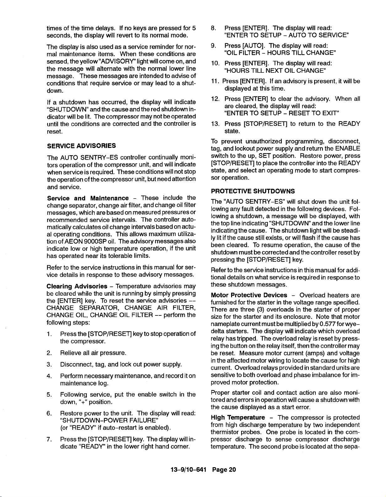
times of the time delays. If no keys are pressed for 5
seconds, the display will revert to its normal mode.
The display is also used as a service reminder for nor-
mal maintenance items. When these conditions are
sensed, the yellow “ADVISORY” light will come on, and
the message will alternate with the normal lower line
message. These messages are intended to advise of
conditions that require service or may lead to a shutdown.
If a shutdown has occurred, the display will indicate
“SHUTDOWN” and the cause and the red shutdown indicator will be lit. The compressor may not be operated
until the conditions are corrected and the controller is
reset.
SERVICE ADVISORIES
The AUTO SENTRY-ES controller continually moni-
tors operation of the compressor unit, and will indicate
when service is required. These conditions willnot stop
the operation of the compressor unit, but need attention
and service.
Service and Maintenance - These include the
change separator, change air filter, and change oil filter
messages, which are based on measured pressures or
recommended service intervals. The controller automatically calculates oilchange intervals based on actual operating conditions. This allows maximum utiliza-
tion of AEON 9000SP oil. The advisory messages also
indicate low or high temperature operation, if the unit
has operated near its tolerable limits.
Refer to the service instructions in this manual for ser-
vice details in response to these advisory messages.
Clearing Advisories - Temperature advisories may
be cleared while the unit is running by simply pressing
the [ENTER] key. To reset the service advisories -CHANGE SEPARATOR, CHANGE AIR FILTER,
CHANGE OIL, CHANGE OIL FILTER -- perform the
following steps:
1.
Press the [STOP/RESET] key to stop operation of
the compressor.
2.
Relieve all air pressure.
3.
Disconnect, tag, and lock out power supply.
4.
Perform necessary maintenance, and record it on
maintenance log.
5.
Following service, put the enable switch in the
down, “+” position.
6.
Restore power to the unit. The display will read:
“SHUTDOWN-POWER FAILURE”
(or “READY” if auto-restart is enabled).
Press the [STOP/RESET] key. The display will in-
7.
dicate “READY’ in the lower right hand corner,
Press [ENTER], The display will read:
8.
“ENTER TO SETUP - AUTO TO SERVICE
Press [AUTO]. The display will read:
9.
“OIL FILTER - HOURS TILL CHANGE
Press [ENTER]. The display will read:
10.
“HOURS TILL NEXT OIL CHANGE
Press [ENTER]. If an advisory is present, it will be
11.
displayed at this time.
Press [ENTER] to clear the advisory. When all
12.
are cleared, the display will read:
“ENTER TO SETUP - RESET TO EXIT”
Press [STOP/RESET] to return to the READY
13.
state.
To
prevent unauthorized programming, disconnect,
tag,”and lockout power supply and return the ENABLE
switch to the up, SET position. Restore power, press
[STOP/RESET] to place the controller into the READY
state, and select an operating mode to start compressor operation.
PROTECTIVE SHUTDOWNS
The “AUTO SENTRY-ES” will shut down the unit fol-
lowing any fault detected in the following devices, Following a shutdown, a message will be displayed, with
the top line indicating “SHUTDOWN” and the lower line
indicating the cause, The shutdown lightwill be steadily litifthe cause stillexists, or will flash if the cause has
been cleared. To resume operation, the cause of the
shutdown must be corrected and the controller reset by
pressing the [STOP/RESET] key.
Refer to the service instructions in this manual for addi-
tional details on what service is required in response to
these shutdown messages.
Motor Protective Devices - Overload heaters are
furnished for the starter in the voltage range specified.
There are three (3) overloads in the starter of proper
size for the starter and its enclosure. Note that motor
nameplate current must be multiplied by 0.577 for wyedelta starters. The display will indicate which overload
relay has tripped. The overload relay is reset by pressing the button on the relay itself, then the controller may
be reset, Measure motor current (amps) and voltage
in the affected motor wiring to locate the cause for high
current. Overload relays provided in standard units are
sensitive to both overload and phase imbalance for improved motor protection.
Proper starter coil and contact action are also moni-
tored and errors in operation will cause a shutdown with
the cause displayed as a start error.
High Temperature - The compressor is protected
from high discharge temperature by two independent
thermistor probes. One probe is located in the com-
pressor discharge to sense compressor discharge
temperature. The second probe is located at the sepa-
13-9/10-641
Page 20

rator discharge and senses the temperature of the air
at the oil separator. The “AUTO SENTRY-ES will shut
the compressor down if temperature exceeds 225° F
(or lower per user adjustment) or if rapid temperature
rise is detected. The location of the high temperature
fault will be displayed.
Thermistor probes are also checked for open or
shorted circuits, or extreme low temperature, and the
display will indicate the location of the defective probe.
~cAuTI0N
diagnostic checks of its own operation and the sensors
to which it is connected. Refer to the service section
for a complete listing of shutdowns and remedial actions.
PROGRAMMING AND SETUP INSTRUCTIONS
FOR THE AUTO SENTRY”-ES CONTROLLER
All compressor control adjustments are made through
the controller keypad. This provides a single location
for alladjustments, coordinates all related controls, and
eliminates the need for additional gauges and meters.
The controller stores all adjustments digitally. These
are permanent unless changed by further program-
ming.
Machine damage will occur if compressor is repeatedly restarted after
high temperature stops operation.
Find and correct the malfunction be-
fore resuming operation.
Separator Differential Pressure - The “AUTO
SENTRY-ES continually monitors the pressure drop
across the oil separator. The unit shuts down at a differential pressure of approximately 15 psid. This becomes active only after the compressor has been running and pressures have had time to stabilize.
High Pressure - The “AUTO SENTRY-ES will first
attempt to unload and blow down the unit if excessive
pressures are detected inthe reservoir or the plant system, If unsuccessful, a shutdown will occur.
Shut down will also occur if a defective transducer is
detected. The display will indicate the location of the
high sensed pressure or transducer (xducer) error.
Check that all adjustments have been properly made,
and all connections are secure.
General - Programming and setup is accomplished
with the PROGRAM keys. In all steps, the [ENTER]
key willcause the controller to accept the displayed val-
ue into memory and advance to the next programming
function. The plus [+] and minus [-] keys will increase
and decrease displayed numeric values, or step
through menu selections. During numeric adjust-
ments, the right [ < ] and left [ > ] arrow keys, move
the cursor (flashing digit) to the position desired. The
number at the cursor will be the number that is changed
bythe [+] and [-] keys. At any point inthe programming
and setup routine, press the [STOP-RESET] key to
exit and return to the READY state without altering the
adjustment.
In all steps of the programming routine, the top line of
the display will give a description of the parameter to be
programmed, while the bottom line shows the variable
that is capable of being altered by programming.
The following is a step by step guide to programming
the “AUTO SENTRY-ES controller.
I
NOTICE
Low Oil Pressure - The “AUTO SENTRY-ES will
shutdown the unit if inadequate oil reservoir pressure
is detected after starting and loading. If this occurs,
check the wiring and piping to the solenoid valves.
Emergency Stop - Pressing the emergency stop button will shut down the unit and the controller. To restart,
pull the button out to its normal position and reset the
controller. Use this for emergency purposes only -use the keypad [STOP/RESET] key for normal controlled stopping.
Power Failure - Following power interruptions, the
controller will remain in a shutdown state (unless programmed for auto restart).
High Vibration (optional) - This optional feature will
shut down the unit if abnormally high vibration is detected.
Other Shutdowns - The controller runs continuous
13-9/10-641 Page 21
Between each step it is necessary to
press the “ENTER” key to restore the
new value and advance to the next
step.
Programming Steps:
1. Stop the compressor before making any adjustments. Ifthe unit is running, press the [STOP/RESET] key to place the control in the “READY”
state. Adjustments can also be performed while
in the “SHUTDOWN” state.
2. Press the [ENTER] key to begin programming. if
the enable switch on the circuit board is in the set
(up) position, the control proceeds to step 7 below.
If the switch is in the “+” (down) position, the controller willdisplay “ENTER TO SETUP - AUTO TO

SERVICE”. Press [ENTER] to go directly to step
7 below, Press [AUTO] to perform the following
steps.
3. The display shows “OIL FILTER” and the hours remaining until the next advisory are displayed on
the bottom line, Press [ENTER] to go to step 4
without any change.
Press [AUTO] only if the oil filter change has been
performed early. This will reset this timer back to
the oil filter interval (see step 19).
4. The display shows “OIL CHANGE and the hours
remaining until the next advisory are displayed on
the bottom line. Press [ENTER] to go to step 5
without any change.
Press [AUTO] only if the oil change has been performed early. This will reset this timer back to the
oil change interval (see step 20).
5. If any service advisories are in effect (yellow ADVISORY indicator is on), they will be displayed.
Press [ENTER] to clear the advisory.
The display will indicate “ENTER TO SETUP -
6.
RESET TO EXIT”. This indicates that all the main-
tenance adjustments have been completed.
Press [STOP/RESET] to go back to the READY
state, or press [ENTER] to go on to step 7.
7. The top line shows “DISPIAY UNITS. The bottom line indicates “ENGLISH” (PSIG, Fahrenheit)
or “METRIC (Bars, Celsius) units of measurement, Select the desired display units and press
[ENTER] to proceed.
8. The top line displays “NUM OF SEQ UNITS. The
bottom line indicates a number inthe range of one
through eight. This will be factory set at “l”. Set
this to a number corresponding to the number of
compressors that are currently installed on this air
system that also have AUTO SENTRY-ES con-
trollers. It should be noted that all” AUTO
SENTRY-ES compressors on the system must
have the same number programmed hereto oper-
ate correctly in SEQUENC-E mode.
NOTICE
Setting the value instep 8 to one indicates that no sequencing is to take
place. Consequently, steps 9, 10, and
11, which relate to sequencing, are
skipped by the
ES”; Programming commences at
step 12.
“AUTO SENTRY-
9. The top line displays “UNIT NUMBER”, The bottom line will again indicate a number of one
through eight and be factory set at “1”. Each
“AUTO SENTRY-ES in a sequenced system
must have a unique number here. The sequence
mode will not function iftwo or more compressors
have the same UNIT NUMBER. Use low numbers
for the most efficient machine-to-machine com-
munications. Example: Use 1, 2, and 3 for a three
compressor installation,
10. The top line displays “TRANSFER INTERVAL”.
The bottom line indicates a number of hours from
1to 5000. It is factory set at 24. This is the number
of hours that this machine will stay in the role of
‘[master” or “lead compressor. Normally it is desirable to set this to the same value on all sequenced units to equalize running hours.
11. The top line displays "LAG START DELAY”. The
bottom line indicates a number from 15 to 600 seconds. It is factory set at 30. This is the length of
time this machine will wait before starting when
the pressure drops below the reset point, Set this
to the same value for all sequenced units. Its setting will depend on the amount of air storage volume in the system. Too small a number will result
in more compressors being started than is necessary to satisfy demand. See “SEQUENCING
COMPRESSORS WITH THE AUTO SENTRY-
ES” for more details on optimizing a sequenced
installation.
12.
The top line displays “BLOWDOWN TIME. The
bottom line indicates a time between 5 and 20 minutes. It is factory set at 10 minutes. This is the
minimum time interval between blowdowns. A
longer blowdown time minimizes wasteful dumping of compressed air when loading is likely to occur ina short time. Longer periods also have been
shown to prevent oil foaming.
13,
The top line displays “AUTO TIME. The bottom
line indicates a time between 5 and 20 minutes.
It too, is factory set at 10 minutes. Its function is
to prevent frequent motor starting, and to allow the
motor a ‘cool-down’ period before stopping.
14.
The top line displays “START TIMER”. The bottom line indicates a time between 3 and 10 seconds. This is the time that the controller spends
in the unloaded ‘start’ mode. On units with facto-
ry-furnished wye-delta starters, this is the time
that the starter is in its ‘start’ mode. Set this for the
time when the motor reaches its maximum speed.
On all other starter types, this should be set for the
time that the motor takes to reach full speed. Ifthe
setup switch is in the up position, the controller re-
turns to the READY state after this adjustment.
13-9/10-641 Page 22

NOTICE
Unit setup adjustments are normally
required only atthetime of unit instal-
lation. To prevent accidental access,
these will not be available if the “SET”
switch is in the up position. The .
“SET” switch is located beneath the
power transformer mounting plate on
the left edge of the main circuit board.
15,
Ifthe switch isinthe down position, “HI SYS PRES
LIM” is displayed on the top line, The bottom line
indicates a value that is factory set 20-25 PSI
above name plate. This is the pressure that will
cause a forced blowdown if approached due to a
malfunction such as a stuck inlet valve or broken
control line. The controller will shut down if this
pressure is exceeded.
The upper limits for the following two adjustments
are based on the setting of the high system pressure limit, If necessary, the controller automatically reduces them following this step, and the display will briefly indicate “ADJUSTING PSET AND
PRES”
16,
The top line displays’’SET PRESSURE. The bottom line indicates a pressure value. Set at the
nameplate rating of the compressor for normal operation. Under NO circumstances, is this adjustment to be set more than the compressor nameplate pressure.
17,
The top line displays, “RESET PRESSURE, The
bottom line indicates a pressure value. This setting determines the point at which machine startup
occurs in AUTO and SEQUENCE modes and
when the compressor will load up from the blown
down condition. Note that RESET PRESSURE
cannot be set within 5 PSI of the SET PRESSURE. It is necessary that all machines to be sequenced have the same SET and RESET PRESSURE setpoints,
The top line displays “REMOTE STOP. The bot-
18,
tom line indicates either “TIMED or “lMMEDlATE. Select the desired response to the remote
input and press [ENTER] to proceed.
19,
The top line displays “FILTER CHNG INTERVAL”.
The bottom line indicates a time interval of 500 to
1000 hours. After the machine has run for the programmed setting, an advisory
requesting an oil filter change.
and press [ENTER] to go on.
will be displayed,
Adjust as desired
The top line displays “OIL CHANGE INTERVAL”.
20,
The bottom line indicates a time interval of 1000
to 8000 hours. After the machine has run for the
programmed setting, an advisory will be displayed, requesting an oil change. Adjust as desired and press [ENTER] to proceed. 8000 hours
is the proper change interval for AEON 9000SP
synthetic oil. See section 5 for proper setting for
AEON lubricants.
21.
The top line displays “HI TEMP LIMIT”. The bottom line indicates 225 degrees F. This isthe maximum (and proper) setting for compressor operation. It may be temporarily lowered to verify the
function of the temperature shutdown system.
22.
The top line displays “FAN TYPE. The bottom
line indicates either “AIR COOLED or “WATER
COOLED”. Select aircooled to place the fan un-
der thermostatic control. This is the preferred setting for air cooled units, Select water cooled to run
the (enclosure vent) fan whenever the main motor
runs. This is the mandatory setting for water
cooled compressors or compressors with remote
elevated coolers. Select the type according to the
type of compressor model.
23.
The top line displays “AUTO RESTART”. The bottom line indicates either “OFF or “ON”. Set this
feature to ON when it is necessary to have the
compressor automatically restart after a power interruption. This feature shall only be enabled
when the owner determines that it is safe to do so,
It is recommended that compressor access be
limited to only trained service personnel when this
feature is used.
24,
This step happens only if the AUTO RESTART
function was set to ON in step 23, The top line displays “RESTART TIME. The bottom line indicates a time between 5 and 60 seconds. It is factory set at 10 seconds. This isthe amount of delay
introduced before restarting after power has been
restored to ensure a stable supply and staggered
starting. Adjust to any value per user preference,
25.
The top line displays “AIR END TYPE. The bottom line indicates either “TURNVALVE or “NON
TURN VALVE. Set as appropriate for the compressor.
26.
In the top line, “SYSTEM VOLUME is displayed.
The bottom line may be selected as “SMALL”,
“MEDIUM”, or “lARGE. This tunes the response
of the modulation control loops to optimize loop
stability. It is factory set to MEDIUM. Set as fol-
lows:
SMALL ifestimated volume is less than ,25 gallon
per CFM.
MEDIUM if estimated volume is between .25 and
1.0 gallon per CFM.
13-9/10-841 Page 23

LARGE if estimated volume is greater than 1.0
gallon per CFM.
~
This setting is not critical. When set to
its most appropriate value, the controller will maintain discharge at the
closest possible value. If not set cor-
rectly, pressure will vary from the de-
sired setpoint to a somewhat greater
degree but the compressor and its
components will not be adversely af-
fected.
27. The top line displays “REMOVE SYS PRESS.
The bottom line displays the current pressure being sensed at the package discharge. At this point
steps must be taken to ensure that system pressure is really zero psig. Remove the line to the
system pressure transducer. Pressing [ENTER]
will now cause the “AUTO SENTRY-ES to calibrate the transducer output to zero PSIG. Obviously, pressure measurement errors will occur if
‘zeroing’ is done with pressure at the transducer.
If large errors are detected, the controller will de-
mand that the transducer be checked.
28. The top line shows "REMOVE RES PRESS. The
bottom line displays the current pressure being
sensed in the reservoir. The reservoir pressure
transducer may now be ‘zeroed’ by following the
steps outlined in 27 above.
29. The display now reads “PRESS CNST RUN TO
JOG MOTOR,” Press the [CONSTANT RUN] key
to briefly energize the starters, and rotate the
compressor 1/4 to 1-1/2 revolutions to allow a
rotation check, This is limited to three tests.
30. This completes the programming and setup procedures for the “AUTO SENTRY-ES controller.
Press the [STOP/RESET] key to return the com-
pressor to the READY state.
SEQUENCING COMPRESSORS WITH THE AUTO
SENTRY-ES
Sequencing compressors with the AUTO SENTRY-
ES controller is as simple as plugging in a telephone to
a wall jack. The only item required to make the system
functional is a standard telephone cable similar to
cables that connect nearly every telephone to its wall
jack. One less cable than the number of compressors
to be sequenced is required. For example, four com-
pressors require three cables. A kit, 200 EAP752, is
available that contains all material needed to sequence
up to five compressors. This kit contains 500 feet of
cable, eight modular connectors, and a crimping tool to
install the connectors. Note that this cable is designed
specifically for this type of communication, and is a
higher grade than most standard phone cables.
In spite of the fact that it is a standard feature and its
inherent installation simplicity, the sequencing function
of a multi-compressor “AUTO SENTRY-ES system is
the most fully featured, functionally complete available
today.
Installation
A proper sequencing installation requires two or more
Gardner Denver rotary air compressors complete with
“AUTO SENTRY-ES controllers, piped into a com-
mon air system, interconnected as described above.
For best performance, pipe the units directly to the re-
ceiver, without any intervening check valves, dryers, or
other restrictions. Size the receiver to prevent exces-
sive drops or rapid rises in pressures during the opera-
tion as described below. All standard practices com-
mon to sound air compressor installations such as
proper sizing of discharge piping, proper electrical sup-
ply and conductor sizing, and grounding are to be ob-
served. The serial communications interface meets
RS-485 standard. This is the most widely used interface in harsh, industrial environments today. However,
communications cables should be routed through metallic conduit to provide them with both mechanical
protection and electromagnetic shielding.
Each control circuit board has two modular jacks that
accept RJ-12 telephone plugs, One jack is vacant; the
other has a short pigtail plugged into it. To interconnect
two compressors, plug the cable into the vacant jack on
each controller. For installations of more than two
units, disconnect the pigtail plug on all controllers except the two at each end of the line. The order of interconnection has no effect on the system operation. The
following conditions are necessary and sufficient for
proper operation:
1, Every compressor must have a cable connecting
itto another compressor. One less cable than the
number of units sequenced must be used.
2. Each board that has only one cable connected to
it must have its pigtail plugged into the unused
jack. All installations will have two such units.
Operation
1. ESTABLISHING THE INITIAL SEQUENCE
Operation of compressors in sequence requires only a
press of the ‘sequence’ key on each compressor in the
system. Since the sequencing algorithm includes provisions for automatic replacement of a failed master or
‘lead’ compressor, it is important for the operator to be
aware of the hierarchy of events when starting the system.
13-9/1
0-841
Page 24
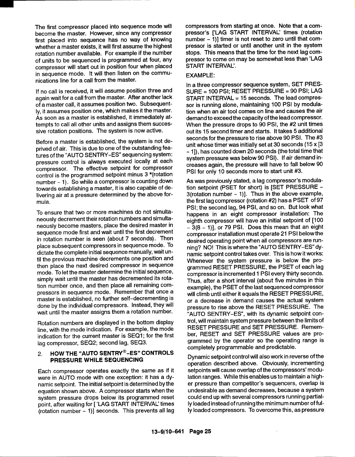
The first compressor placed into sequence mode will
become the master. However, since any compressor
first placed into sequence has no way of knowing
whether a master exists, itwill first assume the highest
rotation number available. For example if the number
of units to be sequenced is programmed at four, any
compressor will start out in position four when placed
in sequence mode.
nications line for a call from the master.
If no call is received, it will assume position three and
again wait for a call from the master. After another lack
of a master call, it assumes position two. Subsequently, it assumes position one, which makes itthe master.
As soon as a master is established, it immediately attempts to call all other units and assigns them successive rotation positions. The system is now active.
Before a master is established, the system is not deprived of air. This is due to one of the outstanding fea-
tures of the “AUTO SENTRY-ES sequencing system:
pressure control is always executed locally at each
compressor. The effective setpoint for compressor
control is the programmed setpoint minus 3 *(rotation
number – 1). So while a compressor is counting down
towards establishing a master, it is also capable of delivering air at a pressure determined by the above formula.
To ensure that two or more machines do not simulta-
neously decrement their rotation numbers and simultaneously become masters, place the desired master in
sequence mode first and wait until the first decrement
in rotation number is seen (about 7 seconds). Then
place subsequent compressors in sequence mode. To
dictate the complete initial sequence manually, wait until the previous machine decrements one position and
then place the next desired compressor in sequence
mode. To let the master determine the initial sequence,
simply wait until the master has decremented its rota-
tion number once, and then place all remaining com-
pressors in sequence mode. Remember that once a
master is established, no further self-decrementing is
done by the individual compressors. Instead, they
wait until the master assigns them a rotation number.
Rotation numbers are displayed in the bottom display
line, with the mode indication. For example, the mode
indication for the current master is SEQ1; for the first
lag compressor, SEQ2; second lag, SEQ3.
2. HOW THE “AUTO SENTRY-ES” CONTROLS
PRESSURE WHILE SEQUENCING
Each compressor operates exactly the same as if it
were in AUTO mode with one exception: it has a dy-
namic setpoint. The initial setpoint is determined by the
equation shown above. A compressor starts when the
system pressure drops below its programmed reset
point, after waiting for [ ‘LAG START INTERVAL’ times
(rotation number - 1)] seconds. This prevents all lag
It will then listen on the commu-
will
compressors from starting at once. Note that a com-
pressor’s ['LAG START INTERVAL’ times (rotation
number - 1)] timer is not reset to zero until that compressor is started or until another unit in the system
stops. This means that the time for the next lag compressor to come on may be somewhat less than ‘LAG
START INTERVAL’.
EXAMPLE:
In a three compressor sequence system, SET PRES-
SURE = 100 PSI; RESET PRESSURE= 90 PSI; LAG
START INTERVAL = 15 seconds. The lead compressor is running alone, maintaining 100 PSI by modula-
tion when an air tool comes on line and causes the air
demand to exceed the capacity of the lead compressor.
When the pressure drops to 90 PSI, the #2 unit times
out its 15 second timer and starts. It takes 5 additional
seconds for the pressure to rise above 90 PSI. The #3
unit whose timer was initially set at 30 seconds (15x [3
- 1]), has counted down 20 seconds (the total time that
system pressure was below 90 PSI). If air demand increases again, the pressure will have to fall below 90
PSI for only 10 seconds more to start unit #3.
As was previously stated, a lag compressor’s modulation setpoint (PSET for short) is [SET PRESSURE 3(rotation number the first lag compressor (rotation #2) has a PSET of 97
PSI; the second lag, 94 PSI, and so on. But look what
happens in an eight compressor installation: The
eighth compressor will have an initial setpoint of [100
- 3(8 - l)], or 79 PSI. Does this mean that an eight
compressor installation must operate 21 PSI below the
desired operating point when all compressors are running? NO! This is where the “AUTO SENTRY–ES dynamic setpoint control takes over, This is how itworks:
Whenever the system pressure is below the pro-
grammed RESET PRESSURE, the PSET of each lag
compressor is incremented 1 PSI every thirty seconds.
Thus, after a short interval (about five minutes in this
example), the PSET of the last sequenced compressor
will climb until either it equals the RESET PRESSURE,
or a decrease in demand causes the actual system
pressure to rise above the RESET PRESSURE. The
“AUTO SENTRY-ES, with its dynamic setpoint con-
trol, will maintain system pressure between the limits of
RESET PRESSURE and SET PRESSURE. Remember, RESET and SET PRESSURE values are programmed by the operator so the operating range is
completely programmable and predictable.
Dynamic setpoint control will also work in reverse of the
operation described above. Obviously, incrementing
setpoints will cause overlap of the compressors’ modulation ranges. While this enables us to maintain a higher pressure than competitor’s sequencers, overlap is
undesirable as demand decreases, because a system
could end up with several compressors running partiallyloaded instead of running the minimum number of fully loaded compressors. To overcome this, as pressure
1)], Thus in the above example,
13-9/1 0-641
Page 25

rises through the range between RESET and SET, the
lag compressors’ PSET’S are now decremented. This
reverses the effect described above during periods of
high demand. The “AUTO SENTRY-ES keeps track
of all functions so there is never any mix-up of setpoints and the proper rotation sequence is always
maintained.
The Automatic Sequence Change
After the master (lead) compressor has served for the
duration programmed (TRANSFER INTERVAL), it relinquishes control and assigns itself the highest available rotation number. The lag compressors detect the
loss of the master and decrement their rotation numbers. Number 2 becomes number 1, the new master;
number 3 becomes number 2, etc.
Whenever the master detects a missing rotation num-
ber, such as when a compressor is turned off that was
previously in the rotation, it will automatically ‘close the
gap’ by decrementing the rotation numbers of all com-
pressors whose rotation numbers were greater than
the missing number. Likewise, if for whatever reason,
the master compressor fails to carry out its role, all lag
compressors begin decrementing their rotation num-
ber until a new master is established. Regardless of
the scenario, the result will always be that the compressors that remain in rotation will always end up with the
lowest possible rotation numbers.
Other Features
Any air system will exhibit pressure differences from
one point to the next.
compressor installation will show ‘minor’ pressure variations between one compressor’s discharge point and
another compressor’s discharge. These points will
also vary from the central system (normally the air storage receiver). The “AUTO SENTRY-ES sequencing
system is designed to tolerate minor variations. These
pressure differences wreak havoc with conventional
sequencers. Central sequencers sense a lower pressure than is seen at each compressor. With such sys-
tems, there is always a chance that the sequencer
could cause a compressor to over pressure due to this
pressure drop. The alternative has been to set the cen-
tral sequencer to a lower pressure to prevent this or al-
low local override of the sequencer by the local pressure control, neither of which is desirable in the scheme
of maintaining plant pressure efficiently with sequencing. The “AUTO SENTRY-ES sequencing system will
automatically adjust the system to prevent over pressures in any individuals.
The “AUTO SENTRY-ES” sequencing system lets
each compressor control itself independently about a
setpoint (PSET) derived to cause staggered operation,
or sequencing. The aforementioned pressure drops
can also cause derogatory effects (main!y skewed, or
Even a well-designed multi-
out of sequence operation) to the sequencing algorithm
used by the “AUTO SENTRY-ES.
Since these pressure variations are not constant (they
willvary due to demand changes, compressor load percentage changes, and number of compressors run-
ning), any scheme to compensate for the pressure variations must be dynamic.
setpoint control feature accomplishes this error correction scheme rather easily.
Here’s how it works: The master continually receives
system pressure values from every machine in the se-
quence rotation. The values are averaged and this average is distributed to all lag compressors. All compressors, lead and lag, then compare their local
pressure reading to the average and adjust their PSET
by the amount of error. The effect is that all compressors are controlling to a single pressure reading, a
reading that is not one that is picked up somewhere removed from the compressor, but an average of actual
discharge pressures.
The pressure displayed on the top line by all sequenced
compressors is this average,
CONNECTION TO EXTERNAL CONTROLS
The “AUTO SENTRY-ES controller offers intercon-
nection points for external controls and indicators. This
allows simple connection to remote controls and indicators, or integration into any plantwide controls system.
Remote On/ Off - Remote on-off control of the sys-
tem requires only a simple two-wire control, with an
isolated contact suitable for 120 volts, 1 amp. This may
be a switch, a timer contact, a relay contact, or a PLC
output. To connect, simply run the two wires to the control enclosure, remove the jumper between terminal 6
and terminal 9 on the terminal strip, and connect the
two wires to terminal 6 and terminal 9.
The air compressor will operate normally in its selected
mode whenever this contact is closed (turned on).
Note that the keypad is always the master control; the
operating mode must be selected at the keypad, and
the remote is not capable of starting a unit after the
STOP/RESET key has been pressed to place the con-
troller inthe READY state. When the contact isopened
(turned off), operation depends on how the controller
has been programmed and what it is doing prior to
opening the contact.
If the compressor was already stopped in automatic or
sequence modes, itwill remain stopped and will not restart until the contact is closed. The display will flash
the message “REMOTE STOP to indicate that it is
waiting for the remote signal.
If the compressor was running in any mode when the
contact was opened, and the remote response is programmed for “IMMEDIATE, the compressor will im-
The exclusive dynamic
13-9/10-641 Page 26

PUR
MINIMUM
PRESSURE
)
FIGURE 4-2- SCHEMATIC TUBING DIAGRAM
mediately unload, blowdown and stop the motors. The
unit isthen in the “REMOTE STOP mode as indicated
above.
If the compressor was running in any mode when the
contact was opened, and the remote response is programmed for “TIMED UNLOAD, the compressor will
immediately unload and blowdown. Itwillthen continue
to run unloaded for whatever period has been programmed for “AUTO TIME (or will complete the remaining auto time if already blown down). After
completion, the motors will stop, and the unit will be in
the “REMOTE STOP mode as indicated above, This
is the preferred setting for automatic remote controls
that may cycle in less than 1/2 hour, as the motor is always cooled evenly and rapid start cycles are prevented.
Alarm Relay - The “AUTO SENTRY-ES controller
provides an alarm relay that maybe connected to a remote mounted indicator light, horn, or into a PLC input
of a plantwide control system. The contact is commercial rated 2 amps at 120 volts. The relay turns on whenever there is a shutdown condition requiring service at
the compressor, and remains off during normal operation, stopping, or power off conditions. The external
connections from the controller are from an isolated
form C (single-pole, double-throw) contact. This al-
lows control of either a “compressor okay” or a “compressor shutdown” remote indicator,
To use this relay, connect the supply wire for the remote
circuit to terminal 21 (relay common) on the terminal
strip. Connect a wire to the indicator from either termi-
nal 19 (normally open) or from terminal 20 (normally
closed). Connect the other side of the indicator to its
neutral.
Serial Communications
If units are NOT connected in sequence, the serial port
is available for communications of compressor data to
external monitoring systems. Data available include all
pressures and temperatures, and a report of internat
service data. This is accessible with a PC or PLC with
an RS-485 communications port. For protocol information, request drawing 200 EAP1255.
OTHER CONTROL DEVICES
Besides the electronic controller noted above, the fol-
lowing components are also used to control operation
of the compressor unit.:
Relief Valve - A pressure relief valve(s) is (are)
installed in the final discharge line and set to approximately 120-1 25% of the unit’s full load operating pres-
13-9/10-641
Page 27

O-RI N
MAIN SPRING
CV SPRING
G
.,/
/
FIGURE 4-3- BLOWDOWN VALVE
sure for protection against over pressure. Periodic
checks should be made to ensure its (their) operation.
The relief valve should be tested for proper operation
at least once every year. To test the relief valve, raise
the system operating pressure to 75% of the relief valve
set pressure and manually open the valve with the hand
lever. Hold the valve open for a few seconds and allow
it to snap shut,
Cv AS
SEMBL
Y
FIGURE 4-4- MINIMUM DISCHARGE PRESSURE /
CHECK VALVE
~WARNING
Operation of unit with improper relief
valve setting can result in severe personal injury or machine damage.
Insure properly set valves are installed and maintained.
/
wARNING
When the relief valve opens, a stream
of high velocity air is released, resulting in a high noise level and possible
discharge of accumulated dirt or oth-
er debris. Always wear eye and ear
protection and stand clear of the discharge port when testing the relief
valve to prevent injury.
~CAUTION
I
Never paint, lubricate or alter a relief
I
I valve. Do not plug vent or restrict dis- I
charge.
I
13-9/1
0-641 Page 28
Blowdown Valve (FIGURE 4-3) - This valve normally is used for control functions, but also serves to relieve
reservoir pressure following a shutdown. The blowdown valve is a two-way solenoid valve which is piped
into the oil reservoir outlet ahead of the minimum pressure valve, When the solenoid is de-energized, the
valve opens and the coolant system is blown down.
When the solenoid is energized, the valve closes to al-
low the coolant system to pressurize. A control air
check valve is provided to ensure that the inlet valve is
closed during blowdown.
Oil Level Gauge (FIGURE 1-6, Section 1, page 3) This gauge is located on the oil reservoir and indicates
the oil level. See section 5 for information on how to
correctly read the gauge and proper lubrication.
I
Minimum
(FIGURE 4-4) - An internal spring-loaded minimum
I
pressure valve is used in the final discharge line to provide a positive pressure on the coolant system of the
I
compressor even ifthe air service valve is fully open to
Discharge Pressure/Check Valve

FROM
AIR FILTER
n~ll
II
VALVE
IFICE.
BLOW DOW
VALVE
,—!
‘0 -1
SEPARATOR
HOUSING
INLET VALVE
! k%
FIGURE 4-5 - INLET VALVE
atmospheric pressure. This valve also functions asa
check valve to prevent back flow of air from the shop
air line when the unit stops, unloads, or is shut down.
The valve incorporates a spring-loaded piston which
maintains approximately 65 psig in the oil reservoir.
When the air pressure on the upstream (reservoir) side
of the valve rises above 65 psig, the spring is overridden and the valve opens to full porting.
The valve does not require maintenance or adjustment,
If the valve fails to function, check the valve stem Oring for sealing, valve orifices for restriction, or valve
and valve seat for burrs and dirt.
The valve is adjustable within a small range. It is adjusted by a screw on the side of the valve. By turning
the screw, the minimum pressure to open the valve increases.
Conversely, backing it out decreases the
minimum pressure required to open the valve,
–SOLENOIO
HOUSING
VALVE
224ECM797
(Ref. Drawing)
inlet Valve (FIGURE 1-4, page 2, and FIGURE 4-5)
- The Inlet valve restricts the inlet to control delivery
and closes to unload the compressor. At shutdown, the
inlet valve closes to prevent the back flow of air.
The inlet valve position is controlled by air pressure in
its piston cylinder, which is controlled by the “Auto
Sentry-ES” through solenoid valves IVC and IVO. As
Pressure to the piston is increased, the valve closes to
restrict air flow and compressor delivery.
Solenoid Valves IVC and IVO - These valves control
position of the inlet valve in response to signals from
the “Auto Sentry -ES.
With both valves de-energized, the normally open IVC valve allows control pressure to the inlet piston to close the valve. If IVC only
is energized, the inlet valve is held in its current posi-
tion. If both valves are energized, control pressure is
relieved from the inlet piston to allow the valve to open.
To service the valve, unscrew the valve cap from the
body. The internal parts will come out after the cap has
been removed, Repair kits are available from your local
authorized Gardner Denver Machinery distributor,
13-9/10-641 Page 29
Pressure Regulator - The pressure regulator is used
to supply a constant and low control pressure to prevent damage to the inlet valve from “slamming.” The
regulator should be set for 25-30 psig.

FIGURE 4-6- SHUITLE VALVE
Shuttle Valve (FIGURE 4-6) - Also known as a
double check valve, the shuttle valve is a device which
will take two (2) supply signals and allow the one with
the highest pressure to pass through. The shuttle valve
is used to provide control air pressure from either the
reservoir or plant air system, as required during different operating conditions.
Purge Air Valve - The purge valve isa normally closed
two-way air actuated valve that admits purge air from
the final discharge manifold to the compressor to counteract the oil knock that occurs in oil-flooded rotary
screw compressors when they are completely unloaded with pressure in the oil reservoir. This valve is
controlled by the same control pressure which controls
the inlet valve.
Turn Valve (Electra-Saver only) (FIGURE 4-7)- The
turn valve isa helical valve which, when rotated, opens
and closes a series of ports cast into the compressor
cylinder. When these ports are open, they direct some
of the air which would otherwise be compressed back
to the inlet, reducing both capacity and power consumption.
Turn Valve Actuator (Electra-Saver only) - The turn
valve actuator is a rotary rack and pinion device which
positions the turn valve according to system demand.
Filtered oil from the compressor sump is directed to the
outboard end of the two actuating cylinders to move the
rack and rotate the valve. Located on the ends of the
cylinders are adjusting screws which limit the travel of
the actuator. When looking at the rear of the compressor, the adjusting screw on the right on the compressor
adjusts the fully closed (full-load) position of the valve.
The full load position of the actuator may be checked
by removing the adjusting screw at the unloaded end
of the actuator (left side of the compressor) and using
a rod to push the pistons to the full load position. The
rod must be clean and free of burrs and scale. Take
care not to scrape the cylinder walls when moving the
pistons.
4
J I
I I I
I I
FIGURE 4-7- TURN VALVE - ELECTRA-SAVER ONLY
13-9/10-641 Page 30
SOLENOID VALVE
-lvc-
213ECM797
(Ref. Drawing)

Solenoid Valves TVC and TVO (Electra-Saver only)
- These valves control the position of the turn valve in
response to signals from the “AUTO SENTRY-ES
controller. With both valves de-energized, equal pressure is applied to both ends of the actuator to hold it in
its present position. If TVC only is energized, the right
side of the turn valve actuator is exhausted to the compressor inlet cavity, causing the turn valve to move towards the full load position. If TVO only is energized,
the left end of the turn valve actuator is exhausted to
the compressor inlet cavity, causing the turn valve to
move towards the unload position.
SENTRY-ES OPERATION” in this section for a description of how the turn valve position iscontrolled during normal operation.
System Pressure Transducer - This transducer is
connected after the minimum pressure valve. It converts the pressure in the plant air system into an electrical signal for use by the “Auto Sentry-ES controller for
modulation and control.
Reservoir Pressure Transducer - This transducer
is connected to the coolant system. Its signal is used
to prevent loaded starts, monitor reservoir pressure,
and monitor the condition of the air/oiI separator.
Air Filter Vacuum Switch - This switch is used to
monitor air filter condition and alert the user if the filter
requires service or replacement.
Discharge Thermistor - This sensor is located directly in the compressor discharge. Its signal is used
to monitor compressor temperature and shut down the
compressor if a coolant problem is detected.
Reservoir Thermistor - This sensor is located near
the separator and is used to monitor temperature and
shut down the compressor if high temperatures are detected.
Emergency Stop Push-Button - This is a maintained push-button, and removes power from the controller outputs regardless of controller status. It is located on the upper section of the panel, next to the
keypad. This should be used for emergency purposes
only - use the keypad “STOP/RESET” for normal controlled stopping.
See “AUTO
~WARNING
Automatic restarting or electrical
shock can cause injury or death.
Open, tag and lockout main discon-
nect and any other circuits before
servicing the unit.
Vibration Switch - The “Auto Sentry-ES controller
has one additional input available for dealer or user
installed optional shutdown switches. The switch is
simply wired in place of the jumper between terminals
7 and 9 of the terminal strip, If the contact is opened,
the compressor will be shut down, and will display
“SHUTDOWN - HIGH VIBRATION”.
The vibration shutdown switch is to be mounted on the
compressor coupling cover, and detects an increase in
vibration that could bean indication of impending dam-
age to the unit. The switch actuates when the selected
level of vibration is exceeded.
The switch must be adjusted when the unit is first
installed. Refer to the switch manufacturer’s instruction manual for complete details.
Control Transformer the incoming power voltage to 110-120 volts for use by
all unit control devices. The transformers employed
are usually connectable for several input voltages, refer to the transformer label for connection prior to ener-
gizing. Two primary and one secondary fuse are provided. Refer to adjacent labeling for replacement
information.
Terminal Strip - This provides connections for all
110-120 volt devices not contained within the enclosure.
Fan Starter - The starter is used to provide control
and overload protection for the cooling fan or the ventilation fan of water-cooled units with enclosure. Over-
load heaters should be selected and adjusted based on
the motor nameplate amps and the instructions located
inside the cover of the electrical enclosure. Three
fuses are provided. Refer to adjacent labeling for re-
placement information.
Main Starter - This starter is used to provide control
and overload protection for the main drive motor. Full
voltage starters employ a single contactor, overload
heaters should be selected and adjusted based on the
motor nameplate amps and the instructions located inside the cover of the enclosure. Wye-delta starters
employ three contractorswhich are controlled sequentially to provide low current starting. For wye-delta
starters, the motor nameplate amps must be first multi-
plied by 0,577 before using the heater table.
Optional Switches - The “Auto Sentry-ES control-
ler has one additional input available for dealer or user
installed optional shutdown switches. If the contact is
opened, the compressor will be shutdown, and will dis-
play “HIGH VIBRATION.”
This control device changes
13-9110-641
Page 31
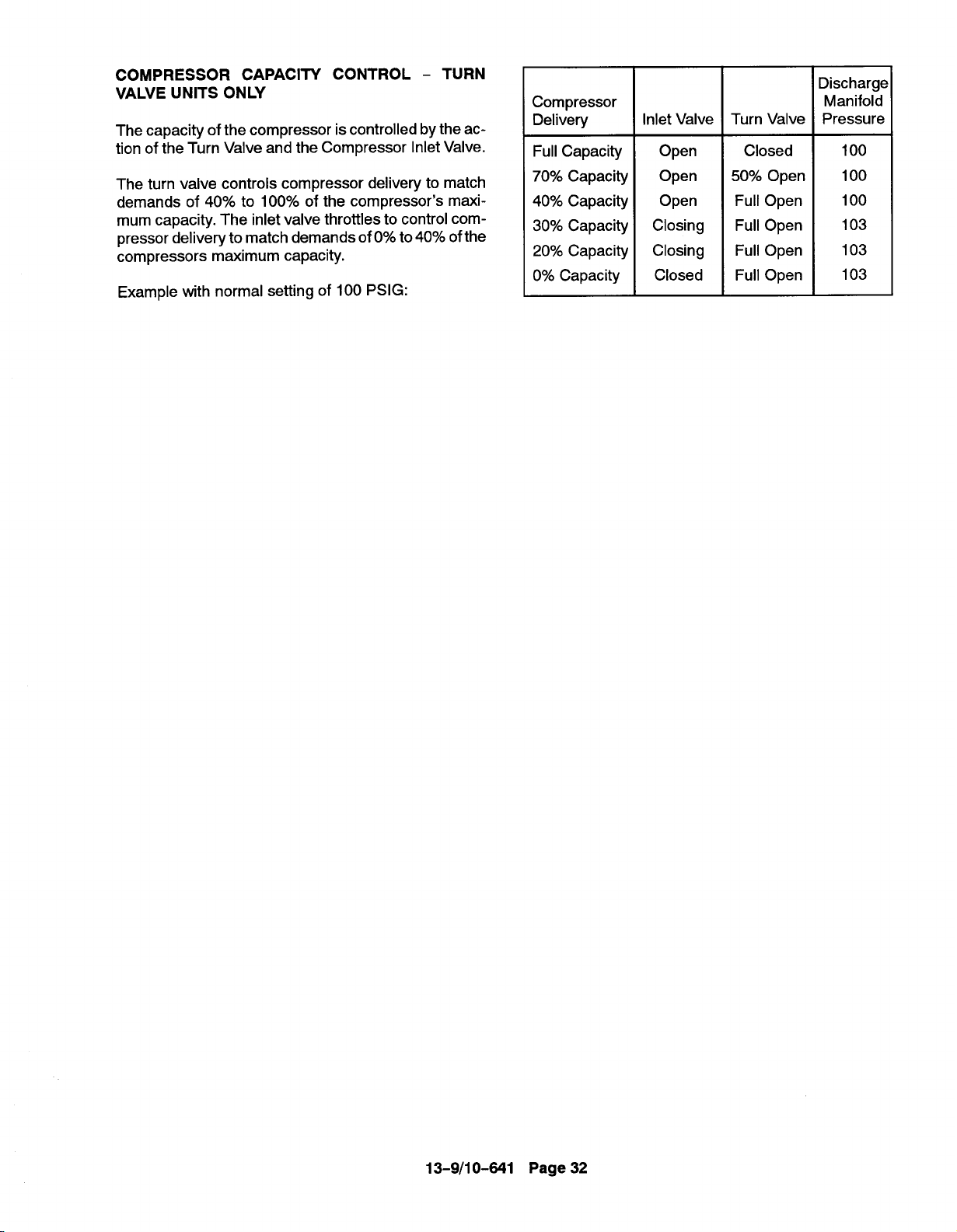
COMPRESSOR CAPACITY CONTROL - TURN
VALVE UNITS ONLY
The capacity of the compressor iscontrolled by the action of the Turn Valve and the Compressor Inlet Valve.
The turn valve controls compressor delivery to match
demands of 40% to 100% of the compressor’s maximum capacity. The inlet valve throttles to control compressor delivery to match demands of O% to 40% ofthe
compressors maximum capacity.
Example with normal setting of 100 PSIG:
Compressor
Delivery
Full Capacity
70% Capacity
40% Capacity
30% Capacity
20% Capacity
0% Capacity
Inlet Valve I Turn Valve
Open
Open
Open
Closing
Closing
Closed
Closed
50% Open
Full Open
Full Open
Full Open
Full Open
Discharge
Manifold
Pressure
100
100
100
103
103
103
13-9/1 0-641 Page 32

ORIFICE
CHECK VALVE
EXHAUST MUFFLER
SOLENOID VALVE ~
BDV” (ON)
SOLENOIDVALVE_
‘IVO” (OFF)
SOLENOIDVALVE>
“IVC-(OFF)
PRESSURE REGWATOR>
SHUTTLE VALVE_
*
SERVICE
VALVE
MINIMUM DISCHARGE
PRESSURE CHECK
II \ / I I
D
D
~
v
VALVE VALVE
ORIFICE
B
c
c
B
c
R
SYSTEM
PRESSK
TRANSDUCER
RESERVOIR
PRESSW
TRANSDUCER
AIR FILTER
VACW WITCH
x
B
7
[
B
B
.
AIR INLET CLOSEO
225ECM797
(Ref. Drawing)
A. FULL OIL PRESSURE
B. FULL AIR PRESSURE
C. CONTROL AIR PRESSURE (15-20 PSI)
D. ATMOSPHERIC PRESSURE OR EXHAUSTING
FIGURE 4-8 - CONTROL Schematic- COMPRESSOR UNLOADED -CONSTANT SPEED MODE
OIL
RESERVOIR
m
EBH & EBM UNITS ONLY
A
OIL
FILTER
REAR VIEW OF COMPRESSOR ‘

EXHAUST MUFFLER>
OR IFICL
lr
1 / I
CHECK VALVE
/-- ORIFICE
B
SOLENOID VALVE~
%DV” (ON)
SOLENOID VALVE=
“IVO”(ON)
SOLENOID VALVE>
“IVC”(ON)
PRESSUREREGULATOR
SHUTTLE VALVE>
+
u
SERVICC
VALVE
A, FULL OIL PRESSURE
B. FULL AIR PRESSURE
C. CONTROL AIR PRESSURE
D. ATMOSPHERIC PRESSURE
B
n
u
MINIMUM
PRESSURE
VALVE VALVE
(15-20 PSI)
OR EXHAUSTING
DISCHARGE
A
CHECK
D
(
SYSTEM
B
B
PRESSURE
TRANSDUCER
_ RESERVOIR
PRESSURE
TRANSDUCER
‘AIR FILTER
VACUUM SWITCH
,U
AIR INLET OPEN
B
-
B
II
-
FILTER
A
226ECM797
(Ref. Drawing)
REAR VIEW OF COMPRESSOR
FIGURE 4-9 - CONTROL SCHEMATIC - COMPRESSOR AT FULL LOAD - CONSTANT SPEED MODE
EBH & EBM UNITS ONLY
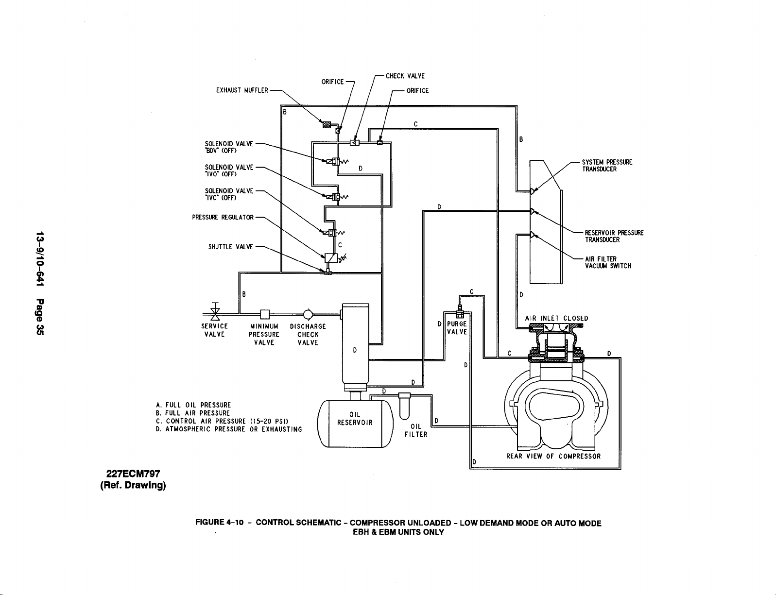
EXHAUST MUFFLER
ORIFICE
CHECKVALVE
ORIFICE
SOLE
BDV’
SOLE
“Ivo”
SOLE
“Ivr
PRESSm
SHU
*
SERVICE
VALVE
A. FULL OIL PRESSURE
B. FULL AIR PRESSURE
C. CONTROL AIR
D. ATMOSPHERIC
PRESSURE (15-20 PSI)
PRESSURE OR EXHAUSTING
B
n A
MINIMUM
PRESSURE
VALVE
B
DISCHARGE
CHECK
VALVE
u
/ / I
[
D
OIL
RESERVOIR
SYSTEM PRESS~E
TRANSMtCER
K
> ~sERvolR p~’jsuRE
TRAN$DUC[R
> AIR FILTER
VACUW SWITCH
AIR INLET CLOSED
D
Ir
D
OIL
FILTER
227ECM797
(Ref. Drawing)
FIGURE 4-10-
CONTROL SCHEMATIC - COMPRESSOR UNLOADED - LOW DEMAND MODE OR AUTO MODE
EBH & EBM UNITS ONLY
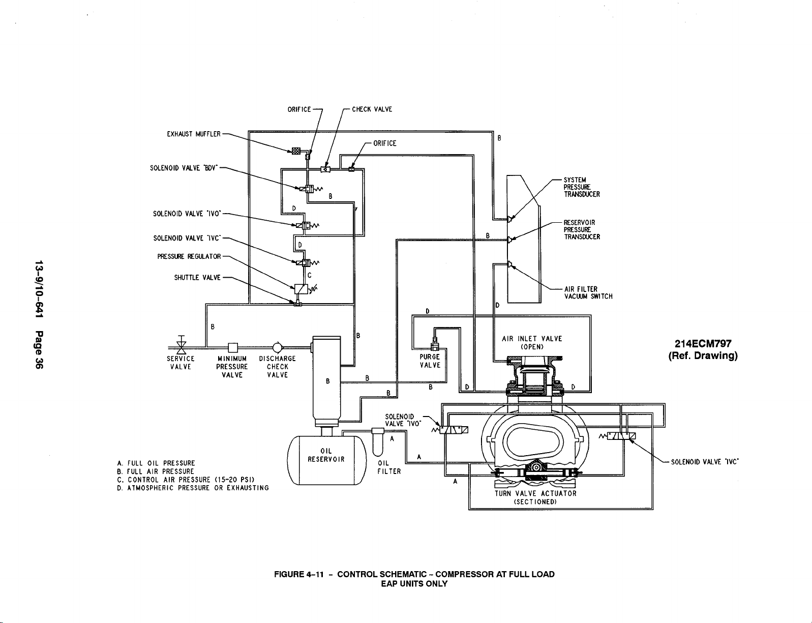
EXHAUSTMUFFLER_
SOLENOIDVALVE ~V”~
SOLENOID VALVE “lV&~
SOLENOIOVALVE “IV’”~
~SS~E KGULATOR
SHUTTLE VALVE>
—
B
+ I n
SERVICE MINIMUM DISCHARGE
VALVE PRESSURE CHECK
II 1 I II.
w
u
VALVE VALVE
‘R’F’CE7rcHEcKvMvE
I /
ORIFICE
IJ
B
o
II
D
A
v
i
5
PURGE
VALVE
B D
.
AIR INLET VALVE
(OPEN)
~ SYSTEM
PRESSURE
TRANS~ER
- RESERVO1’
PRESSUK
TRANSWER
‘AIR FILTER
VACWM SWITCH
214ECM797
(Ref. Drawing)
FULL OIL PRESSURE
A.
FULL AIR PRESSURE
B,
CONTROL AIR PRESSURE (15-20 PSI)
c.
ATMOSPHERIC PRESSURE OR EXHAUSTING
D.
[
II
(SECTIONED)
FIGURE 4-11 - CONTROL SCHEMATIC - COMPRESSOR AT FULL LOAD
EAP UNITS ONLY
- SOLENOID VWVE “IVC”
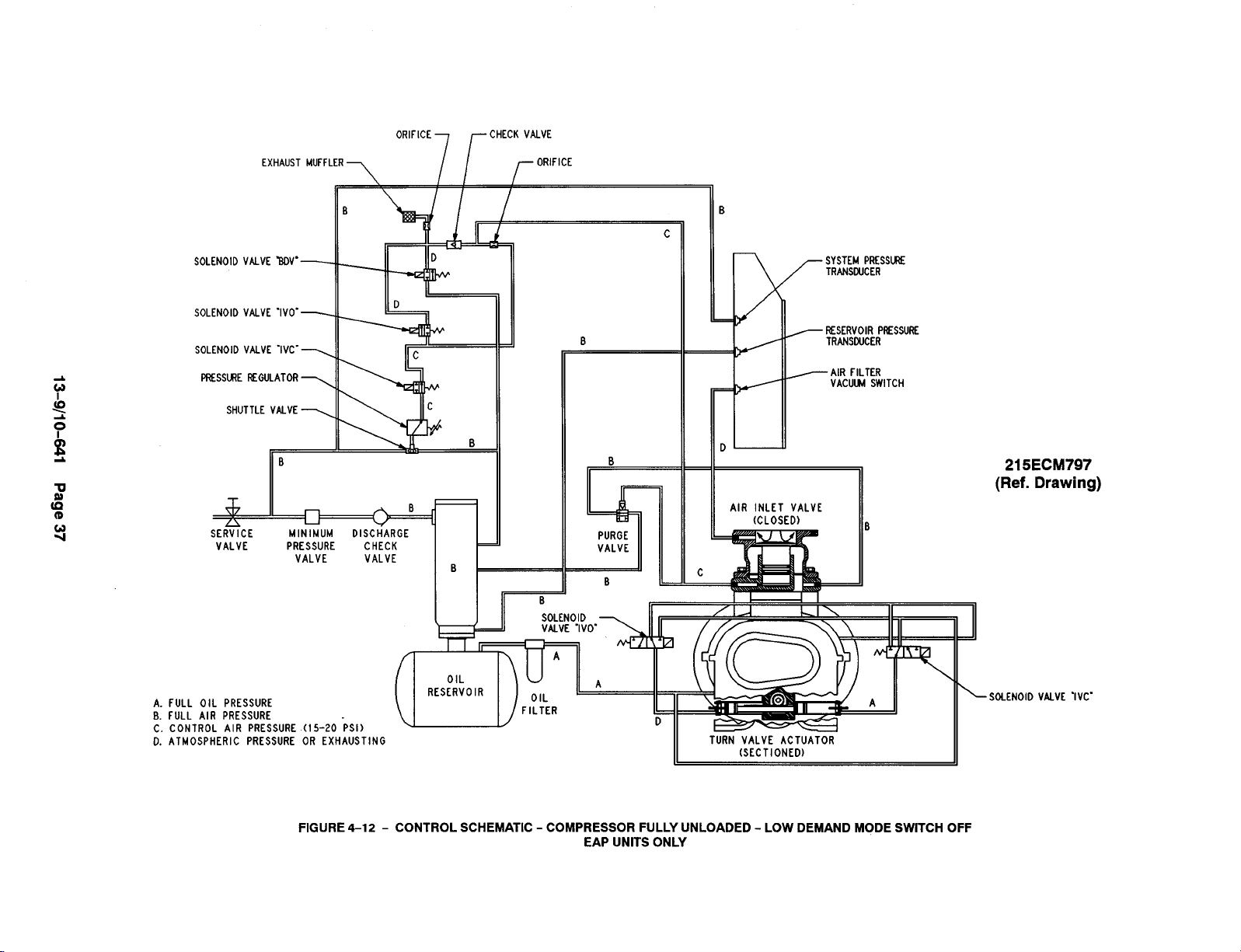
ORIFICE
CHECKVALVE
EXHAUST MUFFLER
[r \ I t I
B
SOLENOID
SOLENOID
VALVE WV”—
VALVE ‘IVO”—
D
‘OLENO’D‘“vE‘lVC”Wrr
PRESSmE REGULATOR>
SHUTTLE VALVEy
h,
Sk
VALVE
PRESSURE CHEC
VALVE VALV
ORIFICE
IL
D
I
(
B
B
B
c
~ ESERVOIR PRESSURE
TRMSOUCER
~ AIR FILTER
VACUM SWITCH
.
215 ECM797
(Ref. Drawing)
AIR INLET VALVE
PURGE
VALVE
5
B
c
L
(CLOSED)
A. FULL OIL PRESSURE
B. FULL AIR PRESSURE
C. CONTROL AIR PRESSURE
D. ATMOSPHERIC PRESSURE
(15-20 Psi)
OR EXHAUSTING
FIGURE 4-12- CONTROL SCHEMATIC - COMPRESSOR FULLY UNLOADED - LOW DEMAND MODE SWITCH OFF
EAP UNITS ONLY
TURN VALVE ACTUATOR
II
(. SECTIONED)
II
SOLENOID
VALVE “IVC”

EXHAUST MUFFLER~
SOLENOIO VAIVE BDV”~
SOLENOID VALVE “lVO-~
SOLENOID VALVE “IVC”_
PRESS~E REGU-ATOR -
SHUTTLE VALVE_
ORIFICE~ /- CHECK VALVE
ORIFICE
i,
*
D
u
SYSTEM PRESSURE
TRANSDUCER
w
- RESERVOIRPRESSURE
TRNSWCER
c AIR FILTER
VACU SWITCH
A
SERVICE
VALVE PRESSURE
A. FULL OIL PRESSURE
B. FULL AIR PRESSURE
C. CONTROL AIR PRESSURE
D. ATMOSPHERIC PRESSURE
MINIMUM OISCHARGE
VALVE VALVE
)
n
u
A
v
CHECK
{
7
D
PURGE
VALVE D
2[ W1_
*‘>
(15-20 PSI)
OR EXHAUST I
FIGURE 4-13- CONTROL SCHEMATIC - COMPRESSOR FULLY LOADED - LOW DEMAND MODE SWITCH ON
EAP UNITS ONLY
.
L
AIR INLET VALVE
c
(CLOSED)
D
216ECM797
(Ref. Drawing)
— SOLENOID VflVE “IVC”

•1 .CON”[,TIWTocam vOARO.
0. ?*,1 1U221NN Uocw
Lcmb
WV - AIR flLIU VM WITCH
WV - K- SOL~lD VMK
Ivc - 1=1 VALE U02c $Wllolb vAlv2
IVO - lVLtT VkVt OUll SOL9101D VM~
L2M C~CC1lti FOR WVi-LthV UOTO~
LOU VOLTAV2 H14H VWIU
Collmcllws Cmtcllans
,,
,2Ivc
, Iv
M
w ,@
10
I
FIGURE 4-14 - WIRING DIAGRAM - 207ECP546
(WYE-DELTA - EBH & EBM UNITS ONLY)
1
I
l~&P
CoNlmLmlznnlw $1!
.“,

NOIC If FM C CONTACT FM M BY 0TH2M,
CWIAC1 0K~72S F~LOMN@ CCU~SSOR WTOOH
RATlll@ 1’20VAC. 2 M.
NOIE Z Fm u82 WITH WTIONN. vIMATIOH WITCIA
KMOVE .BNIKR 42~[N ~l12Al$ 7 & 9, COk
NCC1 4.2, V14RA110N SAllCH C0N7ACT TO T2W
INNS 719.
N07C 9 fOR CU21ROL IV R2MOK COMIAC1, R2K0v2
MtR X~# ~lKNS 6 1 !. CONN2C7 CON-
TACT TO T2RNIIIALS 6 & +.
N07t 4 W*A & mb m FOR M OF WTIMN
cqlcATlw$ CMLL
MOT1 $ V’t12MA WA~ COMTROl $0L2N01b VUVC
1$ u420. WIK 10 rmlnu$ 1; A 10,
s CONUECTIM TO CONTROL 20~.
•1
o s PAN,, 72MlNAl 4L0CKS
M42nb
AIV - AIR FILER VACU92 $MICH
Wv - W*W sm0201B VMV[
lVC - 12U27 Vuvl ao$c $012M01b VUVE
lvo - lKC1 VALV2 m $OL2NOID VNV[
-—
+
J
,1mv ,0
IVC ,0
,2
,3 Ivo
M
W ‘“
FIGURE 4-15 - WIRING DIAGRAM - 209ECP546
(FULL VOLTAGE - EBH & EBM UNITS)
I
—-
co R

•1 .
cow,,,,,” TO CO”m mm.
0. Pm lCRNINU NOcu
If.M CONECIIOM FOR ~Vi-llAO II070RS
LOW VOLTA= H16tl V017A0f
Cwccllws
11 14
t
A
Cwuiclfluls
~t-KLTA
4
8
J
,. -
‘“0
0
uOTOM
FIGURE 4-16- WIRING DIAGRAM - 206EAP546
(WYE-DELTA - EAP UNITS ONLY)
SECTION 5
LUBRICATION
OIL COOLER, OIL FILTER & SEPARATOR
COMPRESSOR OIL SYSTEM (FIGURE 5-1, page
43) cools the compressor, lubricates moving parts and
seals internal clearances in the compression chamber.
~CAUTION
The oil inlet line is connected at the bottom of the oilreservoir. Air pressure inthe oil reservoir forces oilthrough
the oil cooler, thermostatic mixing valve, oil filter and
into the compressor main oil gallery.
The oil passes through internal passages for lubrication, cooling and sealing. The air-oil mixture is then
discharged to the oil reservoir where a large part of
the entrained oil drops out of the air stream; the air
then passes through the final oil separator where most
of the remaining oil is removed. The separated oil is returned to the compressor and the air passes to the final
discharge line.
RECOMMENDED LUBRICANT - Gardner Denver
compressors are factory filled with AEON lubricants.
These lubricants are formulated to the highest quality
standards and are factory authorized, tested and ap-
proved for use in rotary screw compressors. AEON lu-
bricants are available through your authorized Gardner
Denver compressor distributor.
OIL SPECIFICATIONS (Domestic and International) The factory fill compressor lubricant is Gardner Denver
AEON m 9000 SP lubricating coolant which can be
used for year-round operation. AEON m 9000 SP is a
synthetic, extended life lubricant which can extend lu-
bricant change intervals up to 4 times that of a petroleum based lubricant.
Improper equipment maintenance
with use of synthetic lubricants will
damage equipment. Oil filter and oil
separator change intervals remain
the same as for AEON m 4000 -- See
Maintenance Schedule, page 57.
HIGH TEMPERATURE OPERATION - Gardner Denver AEON 9000 SP lubricating coolant will operate at
a sustained discharge temperatureupto210° F (99°C)
when unusually high ambient air temperature is encountered.
I
~DANGER
Air/oil under pressure will cause
severe personal injury or death. Shut
down compressor, relieve system of
all pressure, disconnect, tag and
lockout power supply to the starter
before removing valves, caps, plugs,
fittings, bolts, and filters.
A lubricant analysis program for a periodic check of lubricant quality and remaining life can maximize the
change interval,
~CAUTION
Use of improper lubricants will cause
damage to equipment. Do not mix different types of lubricants or use infe-
rior lubricants.
13-9/10-641 Page 42
~wARNING
High temperature operation can
cause damage to equipment or personal injury. Do not repeatedly restart
the unit after high temperature stops
operation. Find and correct the mal-
function before resuming operation.
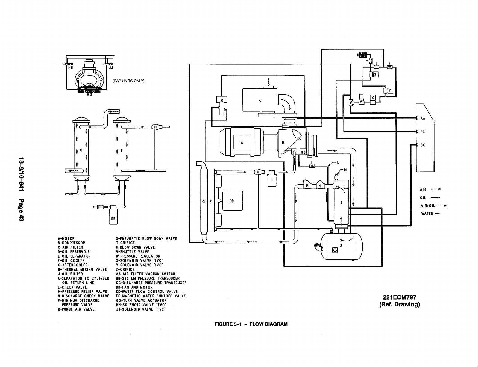
(EAP UNITSONLY)
GG
I
1
I,&
A-MOTOR
B-COMPRESSOR
C-AIR FILTER
D-OIL RESERVOIR
E-OIL SEPARATOR
F-OIL COOLER
G-AFTERCOOLER
H-THERMAL MIXING VALVE
J-OIL FILTER iA:AIR ilLTER VACUUMSWITCH
K-SEPARATOR TO CYLINDER
OIL RETURN LINE
L-CHECK VALVE
M-PRESSURE RELIEF VALVE
N-OISCHARGE CHECK VALVE
P-NINIMUN DISCHARGE
PRESSURE VALVE
R-PURGC AIR VALVE
S-PNEUMATIC BLOW DOWN VALVE
T-ORIFICE
U-BLOW DOWN VALVE
V-SHUTTLE VALVE
W-PRESSURE REGULATOR
X-SOLENOID VALVE “IVC”
V-SOLENOID VALVE “IVO’
Z-ORIFICE
BB-SYSTEM PRESSURE TRANSDUCER
CC-OISCHARGEPRESSURE TRANSDUCER
DO-FANAND MOTOR
EE-WATER FLOW CONTROL VALVE
FF-MAGNETIC WATER SHUTOFF VALVE
GG-TURN VALVE ACTUATOR
HH-SOLENOID VALVE “TVOJJ-SOLENOID VALVE “TVC”
+
1-
—
<
BB
cc
L
1
AIR ----o
F
DD
OIL —
AIR/OIL ----D
WATER ~
P
—
a----
+---
4
)
221 ECM797
(Ref. Drawing)
FIGURE 5-1 - FLOW DIAGRAM

&
‘~A’EV~mE:[O
K- /cOOL’NG ‘OmE
/
2“ HARDPIPE
SUPPLIEDBY CUSTOMER ~lNIF’RE$$ cHECK VAVE)
II
$b
~.<~q~
‘“’’-”- “’’’’” AIR DISCHARGE
KLMUVL rnvm
t ,,8. 7,-I
ACTC1
LIIIL IU w ,LACOOLER
\ /
7
OIL FILL TEE
WITH PLUG
CLOSE TO COOLER
FROM
OIL COOLE~ OIL STOP VALVE
OIL COOLER
L
GATE VALVE
r
SUGGESTED CUSTOMER SUPPLIED
PIPING ARRANGEMENT
TO
1-1/2 HARDPIPE
SRLIEDBY CUSTOMER
201 EAP797
(Ref. Drawing)
o----AIR
-OIL
- AIR/OIL
L
—
-1
c
G
-.,
‘$
+
A - HAIN HOTOR
B - COMPRESSOR
C - INLET FILTER
D - OIL RESERVOIR
E - OIL SEPARATOR
F - OIL COOLER
Q - AFTERCOOLER
H- HIXIN6 VALVE BODY
J- OIL FILTER
K - OIL STOP VALVE
L - CHECKVALVE
M - RELIEF VALVE
N - CHECKVALVE
P - HIN PRESS VALVE
R - PNEUMATIC3 WAYVALVE
AIR FLOW
I
F
t
I,&
—
GATEVALVE
ELEVATED COOLERS
“
/
FIGURE 5-2- OIL FLOW DIAGRAM - REMOTE OVERHEAD MOUNTED
13-9/10-641 Page 44
218ECM797
(Ref. Drawing)

~wARNING
—___--—--
All materials used in Gardner Denver@
compressor units are compatible with
AEON” 9000 SP Lubricating Coolant.
Use caution when selecting downstream components such as air line
lubricating bowls, gaskets and valve
trim.
AEON” 9000 SP Synthetic Lubricant
is not compatible with Iownitrile Buna
Nor acrylic paints. AEON” 9000 SP is
compatible with most air system
downstream components.
Material Safetv Data Sheets (MSDS) are available for
all AEON Iubricants from your authorized Gardner
Denver distributor or by calling 217-222-5400.
REMOTE MOUNTED ELEVATED COOLER ASSEMBLY PROCEDURE - The Compressor package
will be built and tested with the coolers mounted on the
package. On enclosed units, the fan motor will be disconnected after test and the vent fan motor connected
in its place. The vent fan will be mounted in the enclosure. A contactor (starter) will be shipped loose and remote mounted with the cooler by others upon start-up
at the job site. The control box will be wired for remote
elevated coolers at the factory.
NOTICE
AFTERCOOLER
-
,/’
,/
/
/
I
I
1,
0
w
--
--—-.—--.-—
*
\
‘\\
\
i
I
)
/
+ .50
\ R(,339) DR[LL THRu
1/8 NPT
ONE HOLE
k
FIGURE 5-3 - COOLER DRAIN DETAIL
the sys-AFTERCOOLER PIPING - At shutdown of
tern, all units should be drained completely of conden-
sate if there is any possibility of freezing or corrosion
damage. To help remove the condensate, the cooler
may be tapped per FIGURE 5-3 and a drain cock
installed. After opening the drain cock, blow air into the
cooler from a connection on the opposite side of the
cooler. At the same time the connection on the drain
side of the cooler should be plugged. The drain cock
should be left open until the machines are ready for
start-up,
All requirements of local codes
should be followed.
When connecting pipe fittings to the cooler, support the
threaded coupling with a pipe wrench when tightening
the connection. Use silicone sealant on all steel to alu-
minum threaded connections. All piping should be firmIy supported to avoid strain on the cooler manifold and
connections. Flexible connections should be installed
in all interconnecting piping, adjacent to the cooler, to
avoid transmitting piping weight or vibrations to the
cooler elements. Before beginning installations, check
to be sure that no debris or foreign matter remains in
the couplings or cooler bodies.
necting piping is clean to avoid clogging the cooler passages.
Be certain intercon-
13-9/10-641 Page 45
, WARNING
A
Failure to remove condensate from an
idle cooler in freezing temperatures
will cause permanent cooler damage.
Drain condensate after system shutdown. It is the owner/operator’s responsibility to ensure that condensate has been drained and cooler
dried out to prevent cooler damage.
HEAT EXCHANGER (OIL) PIPING - All remote ele-
vated cooler applications must be sent through Engi-
neering for approval and for recommending pipe size.
When the cooling module is removed from the pack-

age, the thermal mixing valve (H) remains on the package. Control group part number 200 ECM4002 will be
mounted on package at the factory. This group controls
the oilstop valve as well as not allowing machine to run
blowndown. See FIGURE 5-2, page 44.
NOTICE
Remote mounted elevated coolers
have a maximum pipe length of 30feet
(9 M) (each way) and a maximum
height of 20 feet (6 M) with a minimum
of fittings. Engineering will review all
remote elevated cooler applications
and recommend pipe size on an individual basis.
should include the engineering recommendation in the special order
sent to Engineering.
Customer Service
ADDITION OF OIL BETWEEN CHANGES
made when the oil level is in
as read while the unit is on. To add oil, follow these
steps:
Be sure the unit is completely off and that no air
1.
pressure is in the oil reservoir.
Disconnect, tag and lockout the power supply to
2.
the starter.
Wipe away all dirt around the oil filler plug.
3.
Remove the oil filler plug and add oil as required
4.
to return the oil level to the center of the green
range on the ,gauge.
Install the oil filler plug, restore power, run and
5.
check for leaks.
DO NOT OVERFILL. The quantity required to raise the
oil level from the red range center of the green range
is shown in FIGURE 5-4, page 47. Repeated addition
of oil between oil changes may indicate excessive oil
:arry-over and should-be investigated.
the red range on the gauge
must be
~DANGER
Kit number EAQ68330 includes the oil stop valve,
check valve and flanges and must be installed on all remote elevated coolers per See FIGURE 5-2, page 44,
and the following instructions.
1. Mount the check valve (90J1 13) as shown.
Mount the drain valves in the lowest section of the
2.
pipe on each side of the cooler connections.
Mount the oil stop valve (90AR243) in the line after
3.
the thermal mixing valve as shown.
Modifications to the control Iines willbe made at the fac-
tory per 288 ECM81 Oschematic. Air to the oilstop valve
must come from the upper fitting inthe separator housing, then pass through the 3-way pneumatic valve.
Control air to the valve must be from the line between
the tee and the orifice in the blowdown muffler line per
FIGURE 5-2, page 44.
down, itwill activate the pneumatic valve and itwill shut
offthe air and vent the line between the pneumatic controlvalve and the oil stop valve to atmosphere. This will
shut the oil stop valve and prevent excessive oil from
running into the reservoir.
Failure to install these parts could result in high oil carryover and cause the machine to shutdown on high discharge temperature.
When the machine blows
Air/oil under pressure will cause
severe personal injury or death. Shut
down compressor, relieve system of
all pressure, disconnect, tag and
lockout power supply to the starter
before removing valves, caps, plugs,
fittings, bolts, and filters.
~DANGER
Compressor, air/oil reservoir, separa-
tion chamber and all piping and tub-
ing may beat high temperature during
and after operation.
~CAUTION
Excessive oil carry-over can damage
equipment. Never fill oil reservoir
above the “FULL” marker.
COLD AMBlENT OPERATION - See “installation for
Cold Weather Operation,” page 9.
13-9/10-641 Page 46
LUBRICANT CHANGE PROCEDURE - Upgrading to
a longer life lubricant is essentially a very worthwhile
practice. Following are the primary steps to be com-

pleted when upgrading or changing the type of lubricant.
Thoroughly drain system:
1.
Drain oil from air end and cooler while hot.
Break low point connections and drain oil
from pipe runs.
—
Dump oil from the filter and reinstall used fil-
ter.
Fillthe system with a 50 percent charge of the new
2.
lubricant:
—
Start the machine and stay there to observe.
Allow the machine to run about five minutes
at temperature, or until temperature stabilizes, then shut down.
3. Thoroughly drain the machine.
Change to a new filter and separator.
4.
FIGURE 5-4- OIL LEVEL GAUGE
5, Fill the system with a full charge of the new lubri-
cant, then reinstall drain plug.
Machine should then be run normally, however,
6.
total run time after the initial changeout should be
50 percent of normal anticipated service life of the
new lubricant.
Drain all lubricant from the system, change
the filter and separator, and replace with a full
charge of the new lubricant.
7. Subsequent lubricant changeouts should be at
normal intervals. (See “Oil Change Interval” and
chart below.)
OIL LEVEL GAUGE (FIGURE 1-6, page 3, and
FIGURE 5-4) indicates the amount of oil in the oil reservoir. Read oil level only when unit is on. In operation
the oil level will fluctuate as the compressor loads and
unloads. Add oil only when the oil is at the bottom of
the red range on the gauge as read when the compres-
sor is on. Drain oil only when the oil level is above the
Discharge
Temperature
center of the green range on the gauge as read when
the compressor is on.
MOISTURE IN THE OIL SYSTEM - In normal humidity and with normal operating temperatures and pressures, the thermal mixing valve controls the oil temperature and prevents moisture contamination of the oil.
Unusual cooling of the oil reservoir, short loaded cycle
in high humidity or malfunctions of the thermal valve
may result in moisture in the oil system which is detrimental to compressor lubrication and could cause oil
carryover. If moisture is observed in the oil reservoir,
drain the moisture and correct the condition causing
the accumulation. See “Compressor Oil System
Check,” page 53 and “Thermal Control (Thermostatic
Mixing) Valve,” page 49.
OIL CHANGE INTERVAL - Recommended oil change
intervals are based on oil temperature. FIGURE 5-5,
shows how the change interval is affected by tempera-
ture.
AEON 4000 AEON 9000 SP
Change Interval Change Interval
to 180°F (82”C)
Up
180° to 190°F (82° to 88°C)
190° to 200° F (88° to 93°C)
200° F+ (93'C)
6000 hrs. 8000 hrs.
4500 hrs. 6000 hrs.
3000 hrs. 4000 hrs.
1500 hrs. 2000 hrs.
FIGURE 5-5- OIL CHANGE INTERVAL
13-9/10-841 Page 47

When operating conditions are severe (very dusty, high
humidity, etc.), it will be necessary to change the oil
‘ more frequently. Operating conditions and the appear-
ance of the drained oil must be surveyed and the oil
change intervals planned accordingly by the user.
Gardner Denver@ offers a free oil analysis program
with the AEON ~ lubricants and we recommend a sam-
ple be sent in at 100 hours on a new unit,
DRAINING AND CLEANING OIL SYSTEM
~DANGER
drain reservoir through the oil filler opening or from
the drain valve.
2.
Ifthe unit is elevated so that the oil reservoir drain
can be used, empty the oil reservoir through the
drain valve to a suitable container or sump.
3.
If the drained oil and/or the oil filter element are
contaminated with dirt, flush the entire system:
reservoir, oil cooler, mixing valve and lines, inspect the oil separator elements for dirt accumulation; replace if necessary. If a varnish deposit exists, contact the factory for recommendations
for removal of the deposit and prevention of varnish.
Air/oil under pressure will cause
severe personal injury or death. Shut
down compressor, relieve system of
all pressure, disconnect, tag and
lockout power supply to the starter
before removing valves, caps, plugs,
fittings, bolts, and filters.
~DANGER
Compressor, air/oil reservoir, separa-
tion chamber and all piping and tub-
ing may beat high temperature during
and after operation.
Always drain the complete system, Draining when the
hot will help to prevent varnish deposit< and carry
oil is
away impurities.
To drain the system, use one of the following methods:
if the unit is not elevated high enough to use the
1.
oil reservoir drain line to drain oil, a small hand,
electric or air operated pump should be
used to
FILLING
OIL RESERVOIR
~DANGER
Air/oil under pressure will cause
severe personal injury or death. Shut
down compressor, relieve system of
all pressure, disconnect, tag and
lockout power supply to the starter
before removing valves, caps, plugs,
fittings, bolts, and filters.
1.
Be sure the unit is completely off and that no air
pressure is in the oil reservoir.
2.
Disconnect, tag and lockout the power supply to
the starter.
3.
Wipe away all dirt around the oil filler plug.
4.
Remove the oil filler plug and add oil as required
to return the oil level to the center of the green
range on the gauge.
5.
Install the oil filler plug and operate the unit for
about a minute allowing oil to fill all areas of the
system. Check for leaks.
6.
Shut down unit, allowing the oil to settle, and be
certain all pressure is relieved.
60, 75& 100 HP
40& 50 HP
(45, 55& 75 Kw)
Refill Capacity For Normal Oil Change . . . . . . . 5.5 U.S. Gallons 8.5 U.S. Gallons
(32 Liters)
Redto Yellow Range . . . . . . . . . . . . . . . . . . . . . . . 1.25 U.S. Gallons
2.0 U.S. Gallons
(7.5 Liters)
FIGURE 5-6- APPROXIMATE OIL SYSTEM CAPACITIES
13-9/10-641 Page 48

7. Add oil, if necessary, to bring level to the center of
the green range on the gauge.
On unloaded operation and after shutdown some oilwill
drain back into the oil reservoir and the oil level gauge
will read “FULL.” DO NOT DRAIN OIL TO CORRECT.
On the next start, oil will again fill the system and the
gauge will indicate operating at the proper level. DO
NOT OVERFILL as oil carryover will result. The quantity of oil required to raise the oil level from “ADD to
“FULL” is shown in FIGURE 5-6, page 48. Repeated
addition of oil between changes may indicate excessive oil carryover and should be investigated.
Use only CLEAN containers and funnels so no dirt en-
ters the reservoir. Provide for clean storage of oils.
Changing the oil W-llbe of little benefit if done in a careless manner.
~CAUTION
Excessive oil carry-over can damage
equipment.
above the “FULL” marker.
Never fill oil reservoir
~DANGER
Air/oil under pressure will cause
severe personal injury or death. Shut
down compressor, relieve system of
all pressure, disconnect, tag and
lockout power supply to the starter
before removing valves, caps, plugs,
fittings, bolts, and filters.
~DANGER
Compressor, air/oil reservoir, separa-
tion chamber and all piping and tub-
ing may beat high temperature during
and after operation.
1.
Stop the unit and be sure no air pressure is in the
oil reservoir.
COMPRESSOR OIL FILTER (FIGURE 5-1) - This
screw on oil filter is a vital part in maintaining a trouble-
free compressor, since it removes dirt and abrasives
from the circulated oil. The oil filter relief valve is located
in the oil filter head. The relief valve opens in the event
the element becomes dirty enough to block the flow of
oil.
~cAuTlON
Improper oil filter maintenance will
cause damage to equipment. Replace
filter element every 1000 hours of op-
eration. More frequent replacement
could be required depending on operating conditions. A filter element left
in service too long may damage
equipment.
Use onlv the replacement element shown on the filter
tag or refer to the parts list for the part number. Use the
following procedure to
not disturb the piping,
replace the filter element. Do
2.
Remove the spin-on element.
3.
Clean the gasket face of the filter body.
4.
Coat the new element gasket with clean lubricant
used in the unit.
5.
Screw the new element on the filter body and tighten by hand. DO NOT OVERTIGHTEN THE ELEMENT.
5.
Run the unit and check for leaks.
COMPRESSOR OIL COOLER - RADIATOR TYPE
(FIGURE 1-5, page 3) - The oil cooler motor and fan
is mounted on the oil cooler module; air is exhausted
through the oil cooler and away from the unit. Do not
obstruct air flow to and from the oil cooler. Allow a minimum of three (3) feet clearance around the cooler.
Keep both faces of cooler core clean for efficient cooling of compressor oil.
THERMAL CONTROL (THERMOSTATIC MIXING)
VALVE (FIGURE 5-7, page 50) is installed in system
as shown in FIGURE 5-1, page 43. This valve is used
to control temperature of the oil in both air-cooled radiator and water-cooled heat exchanger type oilcooler
systems, On start-up with unit cold, element is open to
bypass, allowing oil to pass directly from the reservoir
to compressor during warm-up. As oil warms, element
gradually closes to the bypass allowing more of the oil
from the cooler to mix with oil from the bypass.
13-9/10-641 Page 49
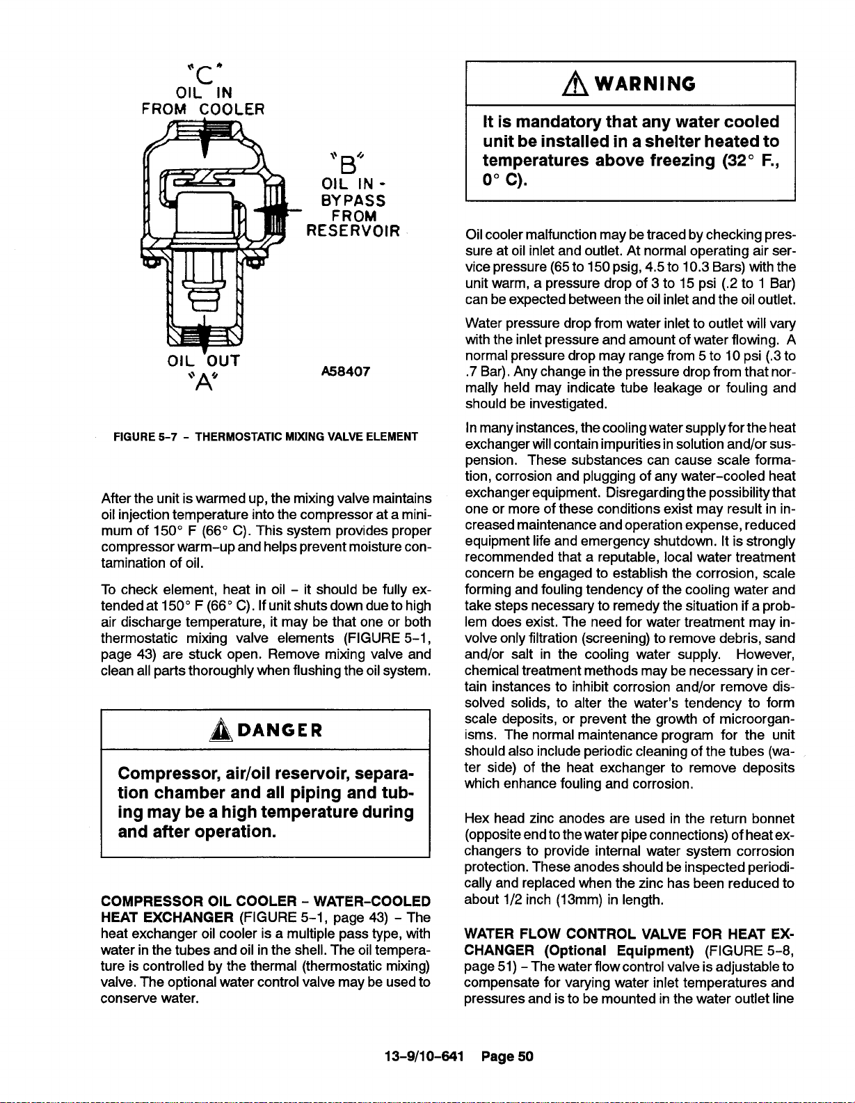
OIL”lN
FROM COOLER
“B’
OIL lN B;:~~S
~wARNiNG
It is mandatory that any water cooled
unit be installed in a shelter heated to
temperatures above freezing (32° F.,
0°c).
RESERVOIR
OIL ‘OUT
A58407
“A’
FIGURE 5-7 - THERMOSTATIC MIXING VALVE ELEMENT
After the unit is warmed up, the mixing valve maintains
oil injection temperature into the compressor at a mini-
mum of 150° F (66° C). This system provides proper
compressor warm-up and helps prevent moisture contamination of oil.
To check element, heat in oil - it should be fully extended at 150° F (66° C). If unit shuts down due to high
air discharge temperature, it may be that one or both
thermostatic mixing valve elements (FIGURE 5-1,
page 43) are stuck open. Remove mixing valve and
clean all parts thoroughly when flushing the oil system.
~DANGER
Compressor, air/oil reservoir, separa-
tion chamber and all piping and tub-
ing may be a high temperature during
and after operation.
COMPRESSOR OIL COOLER - WATER-COOLED
HEAT EXCHANGER (FIGURE 5-1, page 43) - The
heat exchanger oil cooler is a multiple pass type, with
water in the tubes and oil in the shell. The oil temperature is controlled by the thermal (thermostatic mixing)
valve. The optional water control valve may be used to
conserve water.
Oil cooler malfunction may be traced by checking pressure at oil inlet and outlet. At normal operating air service pressure (65 to 150 psig, 4,5 to 10.3 Bars) with the
unit warm, a pressure drop of 3 to 15 psi (.2 to 1 Bar)
can be expected between the oil inlet and the oil outlet.
Water pressure drop from water inlet to outlet will vary
with the inlet pressure and amount of water flowing. A
normal pressure drop may range from 5 to 10 psi (.3 to
.7 Bar). Any change in the pressure drop from that normally held may indicate tube leakage or fouling and
should be investigated.
In many instances, the cooling water supply for the heat
exchanger will contain impurities in solution and/or suspension. These substances can cause scale formation, corrosion and plugging of any water-cooled heat
exchanger equipment. Disregarding the possibility that
one or more of these conditions exist may result in increased maintenance and operation expense, reduced
equipment life and emergency shutdown. It is strongly
recommended that a reputable, local water treatment
concern be engaged to establish the corrosion, scale
forming and fouling tendency of the cooling water and
take steps necessary to remedy the situation if a problem does exist. The need for water treatment may involve only filtration (screening) to remove debris, sand
and/or salt in the cooling water supply. However,
chemical treatment methods may be necessary in cer-
tain instances to inhibit corrosion and/or remove dis-
solved solids, to alter the water’s tendency to form
scale deposits, or prevent the growth of microorganisms, The normal maintenance program for the unit
should also include periodic cleaning of the tubes (wa-
ter side) of the heat exchanger to remove deposits
which enhance fouling and corrosion,
Hex head zinc anodes are used in the return bonnet
(opposite endtothe water pipe connections) of heat ex-
changers to provide internal water system corrosion
protection. These anodes should be inspected periodi-
cally and replaced when the zinc has been reduced to
about 1/2 inch (13mm) in length.
WATER FLOW CONTROL VALVE FOR HEAT EXCHANGER (Optional Equipment) (FIGURE 5-8,
page 51) - The water flow control valve is adjustable to
compensate for varying water inlet temperatures and
pressures and is to be mounted in the water outlet line
13-9/10-641 Page 50
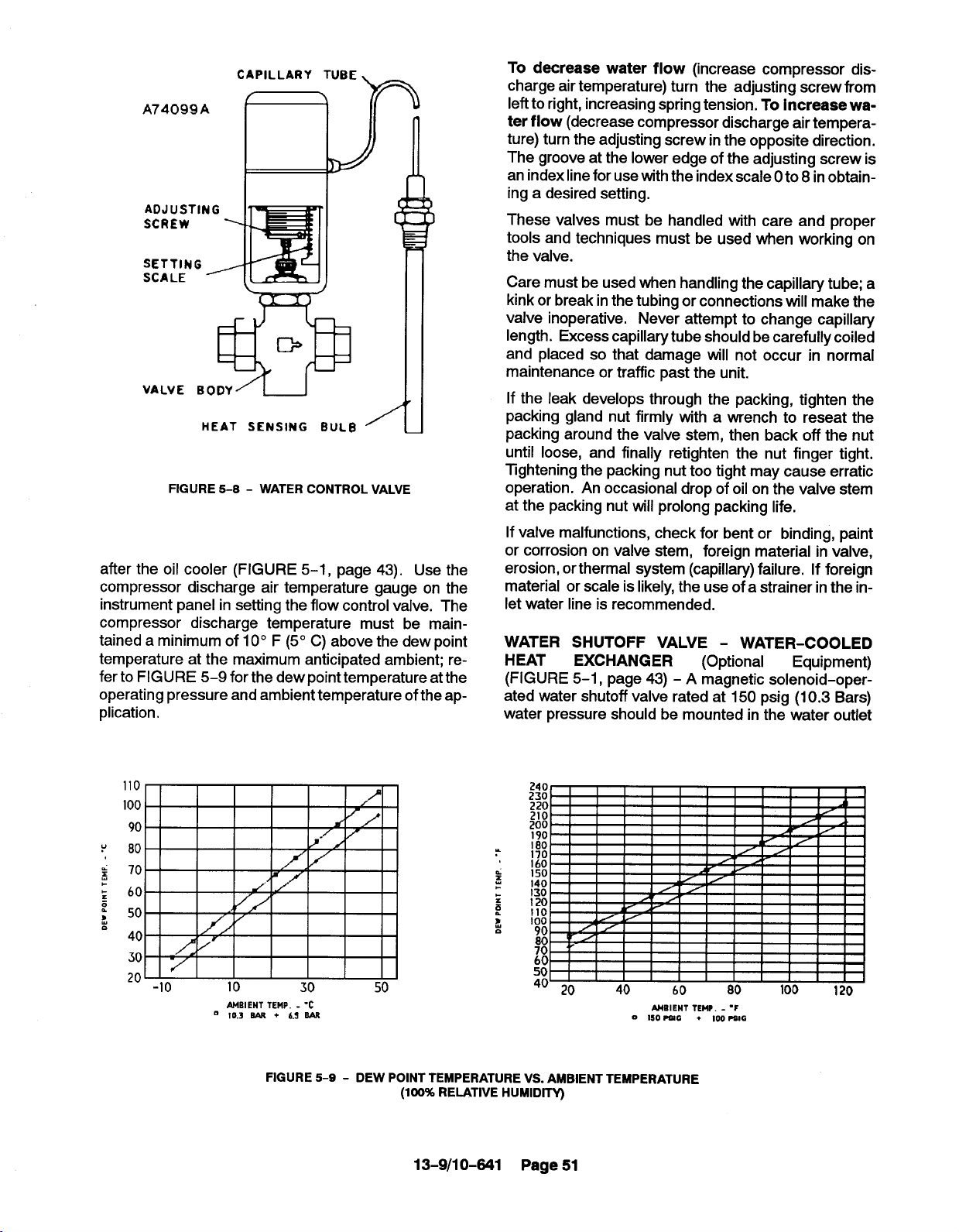
CAPILLARY TUBE
A74099A
v
ADJUSTING
SCREW
SETTING
SCALE -
VALVE BODY= I j
HEAT SENSING BULB
FIGURE 5-8- WATER CONTROL VALVE
❑!
To decrease water flow (increase compressor discharge air temperature) turn the adjusting screw from
left to right, increasing spring tension. To increase water flow (decrease compressor discharge air temperature) turn the adjusting screw in the opposite direction.
The groove at the lower edge of the adjusting screw is
an index line for use with the index scale Oto 8 inobtain-
.
I
[
1
/
ing a desired setting.
These valves must be handled with care and proper
tools and techniques must be used Men wor~ng. on
the valve.
Care must be used when handling the capillary tube; a
kink or break in the tubing or connections will make the
valve inoperative. Never attempt to change capillary
length. Excess capillary tube should be carefully coiled
and placed so that damage will not occur in normal
maintenance or traffic past the unit.
If the leak develops through the packing, tighten the
packing gland nut firmly with a wrench to reseat the
packing around the valve stem, then back off the nut
until loose, and finally retighten the nut finger tight,
Tightening the packing nut too tight may cause erratic
operation. An occasional drop of oil on the valve stem
at the packing nut W-IIprolong packing life.
after the oil cooler (FIGURE 5-1, page 43). Use the
compressor discharge air temperature gauge on the
instrument panel in setting the flow control valve. The
compressor discharge temperature must be maintained a minimum of 10° F (5° C) above the dew point
temperature at the maximum anticipated ambient; referto FIGURE 5-9 for the dew point temperature at the
operating pressure and ambient temperature of the application.
If valve malfunctions, check for bent or binding, paint
or corrosion on valve stem, foreign material in valve,
erosion, orthermal system (capillary) failure. If foreign
material or scale is likely, the use of a strainer inthe inlet water line is recommended.
WATER SHUTOFF VALVE - WATER-COOLED
HEAT
(FIGURE 5-1, page 43) - A magnetic solenoid-operated water shutoff valve rated at 150 psig (10.3 Bars)
water pressure should be mounted in the water outlet
EXCHANGER (Optional
Equipment)
MBIENT TEMP. - ‘C
m 10.3 - + 6.3 EAR
FIGURE 5-9- DEW POINT TEMPERATURE VS. AMBlENT TEMPERATURE
(100% RELATIVE HUMIDITY)
13-9/10-841 Page 51
MBIENT TEMP. - “F
0 150 ?81G
+ 100 =lG

OIL SEPARATOR
PLATE
COVER
separator housing to the compressor cylinder is not
clogged or pinched off, the check valve in the oil return
line is functioning properly, and there is not water or an
oil/water emulsion in the oil.
OIL SEPARATOR—
HOMING
FIGURE 5-10- OIL SEPARATOR
line after the oil cooler. The valve should be wired into
the compressor control circuit so that the
valve opens
to allow water to flow any time the compressor is running. When compressor stops under automatic control, or isshut off manually, the valve should close, stopping water flow through the system. See Wiring
Diagrams in Section 4, pages 39 through 41.
OR
NE
Oil carryover malfunctions of the oil separator are usually due to using elements too long, heavy dirt or varnish deposits caused by inadequate air filter service,
use of improper oil or using oil too long for existing
conditions. A ruptured or collapsed separator element
is usually due to heavy dirt or varnish buildup in the filtering material. Excessive tilt angle of the unit will also
hamper separation and cause oil carryover.
Oil separator element life cannot be predicted; it will
vary greatly depending on the conditions of operation,
the quality of the oil used and the maintenance of the
oil and air filters. The condition of the separator can be
determined by pressure differential gauging or by inspection.
Pressure Differential Gauging - The “CHANGE
SEPARATOR” advisory will flash when the pressure
differential across the oil separator reaches approximately 8 PSID (.55 Bar). Replace the oil separator element at this time. If ignored, the unit will shut down and
the advisorv will illuminate steadily when the pressure
differential reaches 15 PSID (1 Bar).
OIL RESERVOIR - The oil reservoir-separator combines multiple functions into one vessel. The lower half
isthe oil reservoir, providing oil storage capacity for the
system and the top portion, a primary oil separation
means. The reservoir also provides limited air storage
for control and gauge actuation.
COMPRESSOR (GD ELIMINATOR) OIL SEPARATOR located in a separate housing, consists of a renewable cartridge-type separator element and pro-
vides the final removal of oil from the air stream
(FIGURE 5-10).
impinging on the inside of the separator element
Oil
drains directly back into the oil reservoir by gravity, Oil
collected outside the element is returned through tubing to the compressor cylinder.
Oil carryover through the service lines may be caused
by a faulty oil separator, faulty minimum pressure
valve, over-filling ofthe oil reservoir, oilthat foams, oil
return line malfunction or water condensate in the oil,
If oil carryover occurs, inspect the separator only after
it is determined that the oil level is not too high, the oil
is not foaming excessively, the oil return line from the
~CAUTiON
Using an oil separator element at excessive pressure differential can
cause damage to equipment. Replace
the separator when the “Change Separator” advisory appears.
NOTICE
A sudden drop of zero pressure differential or sudden heavy oil carryover
may indicate a ruptured element.
Inspection - After removal of separator element,
shine alight inside the element to reveal areas of heavy
dirt or varnish deposits or breaks (ruptures) in the element media.
13-9/10-841 Page 52

Removal Of Oil Separator For Inspection Or Replacement:
condition. Compressor should beat operating temperature at the time of checks. One-half hour of loaded op-
eration is usually sufficient to reach level-out operating
temperatures.
~DANGER
Air/oil under pressure will cause
severe personal injury or death. Shut
down compressor, relieve system of
all pressure, disconnect, tag and
lockout power supply to the starter
before removing valves, caps, plugs,
fittings, bolts, and filters.
1.
Be certain unit is completely off and that no air
pressure is in the oil reservoir.
2.
Disconnect, tag and lockout power supply to the
starter.
3.
Remove screws holding the top pIate to the separator housing. Liftthe top plate from the separator
housing.
4.
Lift the separator from the separator housing.
5.
Inspect and/or replace the separator as neces-
sary. Be sure the o-ring is not damaged. Before
installing (or reinstalling) any separator apply
grease to the o-ring. Oil will be wiped off by the
chamfer and the o-ring could be damaged.
6.
Remove any gasket material adhering to top plate
or separator housing, and install new gasket.
Air and Oil Discharge Temperature -165° to 195°
F (74° to 910 C) - Read at gauge on the instrument
panel or check with a thermometer at the discharge
housing.
Compressor Oil Inlet Temperature -150° to 160° F
(66° to710 C) - Install a tee at the oil filter outlet and
check with a thermometer.
Oil Inlet Pressure - Check at the fitting in the line near
the compressor oil inlet. With air receiver pressure at
100 psi (6.9 Bar), oil inlet pressure should be 55-60
psig(3.8-4.l Bar).
Oil Cooler Oil Pressure Differential (Air-Cooled
Radiator) - Check differential across oil system by
measuring oil inlet pressure as described above.
Oil Cooler Oil Pressure Differential (Water-Cooled
Heat Exchanger) -2 to 25 PSID (,1 to 1.7 Bar) (65 to
150 PSIG, 4.5 to 10.3 Bars Receiver Pressure) Check that oil inlet pressure is corrector measure the
differential between drains on the oil cooler shell.
Oil Cooler Temperature Differential (Air-Cooled
Radiator) - The oil temperature differential depends
on the temperature of the air at the oil cooler fan and
cleanliness of core faces, As ambient temperatures
and core restrictions increase, the oilcooler outlet tem-
perature will increase. The oil inlet temperature is
approximately the same as air discharge temperature
- see the gauge on the instrument panel. The outlet oil
temperature may be checked by installing a tee at the
oil filter outlet.
7.
Lower the separator into the housing and center
the separator on the chamfer. Press separator
down into the housing. Do not use excessive
force as separator damage can occur.
8.
Place the spacer on the indent in the separator.
Seat the top plate to the separator, spacer and
separator housing.
screws.
9,
Run the unit and check for leaks.
COMPRESSOR OIL SYSTEM CHECK - The following readings are based on ambient temperature of 80°
F (27° C) for air-cooled oil cooler and 80° F inlet water
on water–cooled oil cooler, with the system in good
Install and tighten all cap
13-9/10-641 Page 53
Oil Cooler Temperature Differential (Water-Cooled
Heat Exchanger) - The oiltemperature differential de-
pends on the inlet water temperature and the water flow
rate permitted by the water flow control valve setting.
The oil inlet temperature is approximately the same as
the air discharge temperature - see the gauge on the
instrument panel. The oil outlet temperature may be
checked by installing a tee at the oil filter outlet.
Oil Cooler Water Pressure Differential (Water-
Cooled Heat Exchanger) - The water pressure differ-
ential through the heat exchanger will depend on the
supply pressure, flow rate, cooler tube cleanliness and
outlet pressure. The inlet and outlet water pressure
may be checked at the pipe fittings supplied by the cus-
tomer.

SECTION 6
AIR FILTER
AIR OUTLET +
q
AIR INTLET
*
3.
Wash the element by soaking about 15 minutes in
warm water with a mild nonsudsing detergent.
Rinse the element thoroughly with clean water; a
hose may be used if the water pressure does not
exceed 40 psig (2.8 Bars).
4. Inspect the element for ruptures or cracks in the
pleated media; replace the element if any are
found. Inspect the gasket on the bottom (outlet
end) of the element; replace the entire element if
the gasket is damaged. A spare element will keep
down time to a minimum.
AUTOMATIC UNLOAOER
FIGURE 6-1 - HEAW DUTY AIR FILTER (STANDARD)
HEAVY-DUTY AIR FILTER (FIGURE 6-1) furnished
as standard equipment on units with an enclosure is a
heavy-duty washable element dry type air filter. The
air filter must receive proper maintenance ifmaximum
service is to be obtained from the unit. Establishing adequate and timely filter service is MOST IMPORTANT.
An improperly maintained air filter can cause a loss of
compressor air delivery.
Filter Element - Service the air filter element when the
“CHANGE AIR FILTER” LED is illuminated. Clean every 50 to 150 operating hours depending on dust con-
ditions.
NOTICE
Use only genuine Gardner Denver air
filter elements on Gardner Denver
compressor units. Genuine parts are
available through your authorized
Gardner Denver distributor.
5. Allow the element to air dry COMPLETELY. Do not
expose the element to heat over 1500 F (66° C).
Install the element in the filter body and fasten se-
curely with the wing nut.
WARNING
Do not oil this element. Do not wash
in inflammable cleaning fluids. Do
not use solvents other than water. improper cleaning may damage the element.
NOTICE
I
Never operate the unit without the element. Never use elements that are
damaged, ruptured or wet. Never use
gaskets that won’t seal. Keep spare
elements and gaskets on hand to reduce downtime. Store elements in a
protected area free from damage, dirt
and moisture. Handle all parts with
care.
To service:
1. Remove the wingnut and pull out the filter element,
2. Visually inspect the element. If cleaning is not necessary, reinstall the filter element. If the element
requires cleaning, follow steps 3, 4 and 5.
13-9/10-641 Page 54
Filter Element Life - The element should be replaced
after six (6) cleanings or if:
1. Visual inspection indicates a rupture, crack or pin
hole in the pleated media. Inspection should be
done by placing a bright light inside the element.

2. Pressure drop through a filter with a freshly
cleaned element is below three (3) inches (76
mm) of water with the compressor running at full
Ioad - this would indicate a rupture or crack.
Inlet Tube - Inspect the inlet screen and tube for dirt
accumulation each time the filter is serviced. Clean the
tube when required by ramming a clean dry cloth
through the tube. Wipe the inside of the filter body to
remove any dirt falling from the inlet tube before reinstalling the element.
Causes of short element life include: severe dust
conditions, infrequent servicing, improper cleaning, or
contamination by oil or chemical fumes.
13-9/10-641 Page 55

SECTION 7
COUPLING
RADIUS EDGE
UP TOWARO OUTSIDE
DIAMETER OF COUPLING
~co”” ‘CR’”
8
L
-1
23 FT-LBS
(17 N-M)
SET SCREUS
50 FT-LBS
(37 N-M)
*
DOWN TOWARD SHAFT
FIGURE 7-1 - INSTALLATION OF COUPLING CUSHIONS
~DANGER
Rotating
machinery
personal injury or death. Turn the unit
completely off, open the main
disconnect, tag and lockout before
servicing the coupling.
COUPLING - The motor and compressor are direct
connected by a resilient type flexible coupling with several individual cushions. The coupling does not require
lubrication.
Ifmaintenance on mating parts is requires, reassemble
coupling as follows:
Individual Cushion Design (FIGURE 7-1)
can cause
4L
3.4.Working through the coupling guard opening, center the coupling over the gap between the shafts,
maintaining the gap as shown in FIGURE 7-1 between the ends of the jaws on one coupling body
and the flange on the opposite coupling body.
Tighten set screws in each coupling body.
Insert individual cushions as shown in
FIGURE 7-1 and slide the collar over the cushions and secure with cap screws. Reinstall the
cover plate.
1/16 MIN 1/8 MAX
(1,6 mm to 3.2 mm)
/~\ DANGER
Rotating machinery can cause person-
al injury or death. Do not operate unit
with either the coupling guard or the
collar removed. All bolts and screws
must be properly tightened.
1. Slide coupling halves over shaft extensions. Be
sure the collar is installed on the shaft behind one
coupling body,
Assemble the motor to the compressor.
2.
13-9/10-641
Alignment - The coupling is permanently
the flanges on the compressor and motor.
Page 56
aligned by
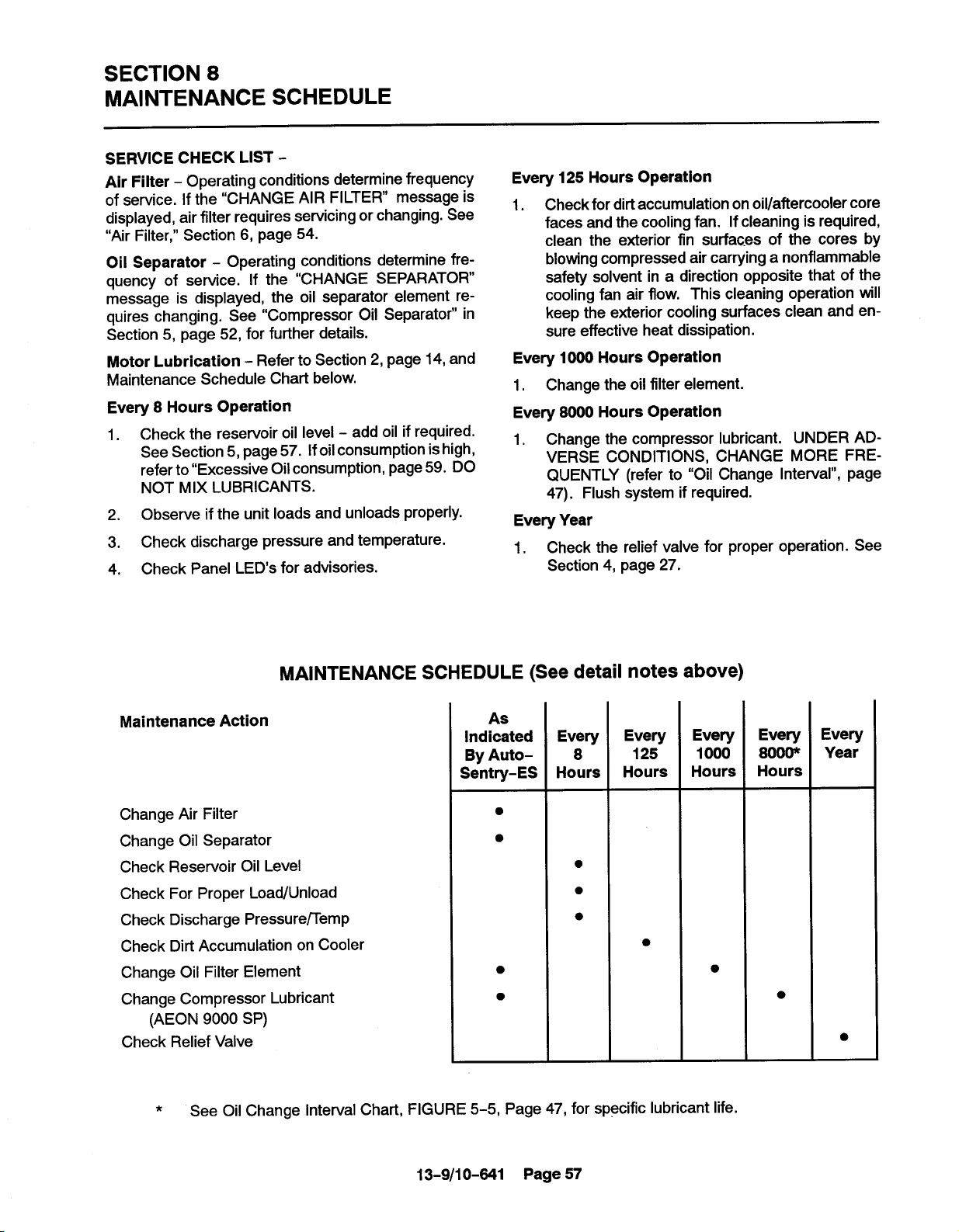
SECTION 8
MAINTENANCE SCHEDULE
SERVICE CHECK LIST Air Filter - Operating conditions determine frequency
of service. If the “CHANGE AIR FILTER” message is
displayed, air filter requires servicing or changing. See
“Air Filter,” Section 6, page 54.
Oil Separator - Operating conditions determine frequency of service. If the “CHANGE SEPARATOR”
message is displayed, the oil separator element requires changing. See “Compressor Oil Separator” in
Section 5, page 52, for further details.
Motor Lubrication - Refer to Section 2, page 14, and
Maintenance Schedule Chart below.
Every 8 Hours Operation
1. Check the reservoir oil level - add oil if required.
See Section 5, page 57. Ifoil consumption is high,
refer to “Excessive Oil consumption, page 59. DO
NOT MIX LUBRICANTS.
2. Observe if the unit loads and unloads properly.
3. Check discharge pressure and temperature.
4. Check Panel LEDs for advisories.
Every 125 Hours Operation
Check for dirt accumulation on oil/aftercooler core
1.
faces and the cooling fan. If cleaning is required,
clean the exterior fin
surfaces Of the cores by
blowing compressed air carrying a nonflammable
safety solvent in a direction opposite that of the
cooling fan air flow, This cleaning operation will
keep the exterior cooling surfaces clean and en-
sure effective heat dissipation.
Every 1000 Hours Operation
Change the oil filter element.
1.
Every 8000 Hours Operation
Change the compressor lubricant. UNDER AD-
1.
VERSE CONDITIONS, CHANGE MORE FRE-
QUENTLY (refer to “Oil Change Interval”, page
47). Flush system if required.
Every Year
Check the relief valve for proper operation. See
1.
Section 4, page 27. “
MAINTENANCE SCHEDULE (See detail notes above)
Maintenance Action
Change Air Filter
Change Oil Separator
Check Reservoir Oil Level
Check For Proper Load/Unload
Check Discharge Pressure/Temp
Check Dirt Accumulation on Cooler
Change Oil Filter Element
Change Compressor Lubricant
(AEON 9000 SP)
Check Relief Valve
*
See Oil Change Interval Chart, FIGURE 5-5, Page 47, for specific lubricant life.
As
Indicated
By Auto-
Sentry-ES
●
●
●
●
Every
8
Hours
●
●
●
Every
125
Hours
●
Every
1000
Hours
Every
8000*
Hours
●
Every
Year
●
13-9/10-841 Page 57

SECTION 9
TROUBLE SHOOTING
SYMPTOM
Compressor fails to start. 1.
Compressor starts but
stops after a short time.
POSSIBLE CAUSE
Wrong lead connections.
Blown fuses in control
2.
box.
Motor starter overload
3,
heaters tripped.
Pressure in reservoir.
4.
Read error message on
5.
control panel.
6,
Remote Contact is open
(terminals 6 & 9).
1.
High discharge temperature.
REMEDY
Change leads.
1.
Replace fuse,
2.
Reset and investigate
3.
cause of overload.
Inspect blowdown valve.
4.
and muffler.
Take appropriate action.
5.
See Section 4.
6.
Replace switch or jumper.
See “High Discharge
1.
Air Temperature,” this
section, page 59.
Compressor does not
unload (or load).
Compressor cycles from
load to unload excessively.
High discharge
2.
temperature switch
malfunction.
3.
Blown fuse in starter/
control box.
4.
Motor starter overload
heaters trip.
Improperly adjusted
1.
control.
2,
Air leak in control
lines.
3.
Restricted control line.
4,
Blowdown valve malfunction.
1.
Insufficient receiver capacity.
2.
Restriction in control tubing.
Replace switch.
2.
3.
Replace fuse
(investigate if fuses
continue to blow).
Reset and investigate
4.
cause of overload.
1.
Refer to Section 4
and adjust control.
2.
Determine source of
leak and correct.
3.
Clean control lines.
4.
Repair, clean or replace
valve.
1.
Increase receiver size.
2.
Inspect and clean control
tubing.
13-9/10-841 Page 58

SYMPTOM
Compressor is low on
delivery and pressure.
High discharge air
temperature.
POSSIBLE CAUSE
Restricted air filter.
1.
Sticking inlet valve.
2.
Unload pressure adjusted
3,
too low,
Minimum pressure valve
4.
stuck closed.
1,
Thermostatic mixing
valve stuck
2,
Dirty
3.
Insufficient cooling
air flow.
Clogged oil filter or
4.
cooler (interior).
5.
Low compressor oil.
open.
or clogged cooler face.
REMEDY
Clean or replace filter.
1.
Inspect and clean inlet
2.
valve.
Adjust the unload pressure.
3.
See Section 4, page 18.
Disassemble and clean
4.
valve.
Repair or replace valve.
1.
Clean cooler.
2.
Provide unrestricted supply
3.
of cooling air.
Replace filter or clean
4.
cooler.
Add oil to proper level.
5.
See “Oil Carryover”, below.
Excessive Oil Consumption
Oil Carry-Over
1.
Oil carryover through lines.
Oil leaks at all fittings
2.
and gaskets.
Overfilling the reservoir.
1.
1.
Tighten or replace fittings
2.
or gasket.
Drain excess oil from
1.
system.
~DANGER
Air/oil under pressure will cause severe personal injury or death. Shutdown com-
pressor, relieve system of all pressure, disconnect, tag and lockout power supply
to the starter before removing valves, caps, plugs, fittings, bolts, and filters.
Clogged, broken or loose
2.
oil return lines
Ruptured oil separator
3.
element.
Loose assembly.
4.
Foam caused by use of 5.
5.
incorrect oil.
Inoperative minimum 6,
6.
pressure valve.
2.
Tighten or replace faulty
lines.
3.
Replace element.
4.
Tighten all fittings and
gaskets.
Use Gardner Denver@
AEON m 9000 SP
Lubricating Coolant.
Clean out or replace valve.
13-9/10-641 Page 59

SYMPTOM
Oil Carry-Over (Continued)
POSSIBLE CAUSE REMEDY
7, Operation atelevated
discharge temperatures.
8. Scavenge line check
valve failure.
9. Water condensate in oil.
7,
8.
9.
Reduce temperature. See
High Discharge Air
Temperature, page 59,
this section.
Replace check valve.
Check oil reservoir temperature and if low, change”
thermal mixing valve element
to higher temperature.
I
NOTICE
Gardner Denver factory remanufactured replacement compressor air end units
are available from your authorized distributor, on an exchange basis, for all rotary
screw compressor units.
I
13-9/10-641 Page 60
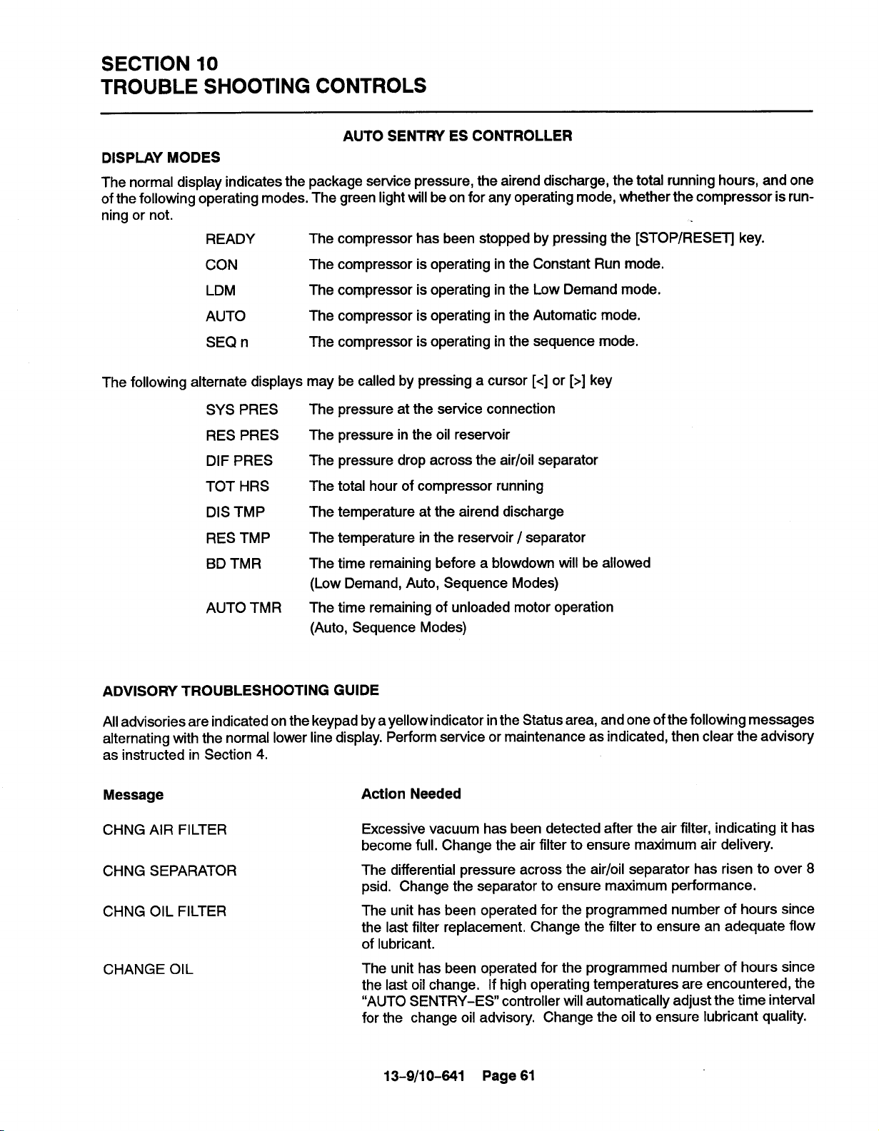
SECTION 10
TROUBLE SHOOTING CONTROLS
AUTO SENTRY ES CONTROLLER
DISPLAY MODES
The normal display indicates the package service pressure, the airend discharge, the total running hours, and one
of the following operating modes, The green lightwill be on for any operating mode, whether the compressor is run-
ning or not.
READY
The compressor has been stopped by pressing the [STOP/RESET] key.
CON
LDM
AUTO
SEQ n
The following alternate displays may be called by pressing a cursor [<] or [>] key
SYS PRES
RES PRES
DIF PRES
TOT HRS
DIS TMP
RES TMP
BD TMR
AUTO TMR
The compressor is operating in the Constant Run mode.
The compressor is operating in the Low Demand mode.
The compressor is operating in the Automatic mode.
The compressor is operating in the sequence mode.
The pressure at the service connection
The pressure in the oil reservoir
The pressure drop across the air/oil separator
The total hour of compressor running
The temperature at the airend discharge
The temperature in the reservoir/ separator
The time remaining before a blowdown will be allowed
(Low Demand, Auto, Sequence Modes)
The time remaining of unloaded motor operation
(Auto, Sequence Modes)
ADVISORY TROUBLESHOOTING GUIDE
All advisories are indicated on the keypad by a yellow indicator in the Status area, and one of the following messages
alternating with the normal lower line display. Perform service or maintenance as indicated, then clear the advisory
as instructed in Section 4.
Message
CHNG AIR FILTER
CHNG SEPARATOR
CHNG OIL FILTER
CHANGE OIL
Action Needed
Excessive vacuum has been detected after the air filter, indicating it has
become full. Change the air filter to ensure maximum air delivery.
The differential pressure across the air/oil separator has risen to over 8
psid. Change the separator to ensure maximum performance.
The unit has been operated for the programmed number of hours since
the last filter replacement, Change the filter to ensure an adequate flow
of lubricant.
The unit has been operated for the programmed number of hours since
the last oil change. If high operating temperatures are encountered, the
“AUTO SENTRY-ES controller will automatically adjust the time interval
for the change oil advisory. Change the oil to ensure lubricant quality.
13-9/10-641 Page 61

ADVISORY TROUBLESHOOTING GUIDE (Continued)
Message
HIGH TEMP OPER
LOW AMB TEMP
SHUTDOWN TROUBLESHOOTING GUIDE
All shutdowns are indicated on the keypad by the word “SHUTDOWN on the top line of the display, and one of the
following messages on the lower line of the display. The red indicator in the Status area will be steadily lit while the
conditions exist, and will flash after the condition has been corrected. Perform service as indicated. Press the
[STOP/RESET] key to clear the shutdown.
Message
CHANGE SEPARATOR
CHECK CN7
Action Needed
The temperature was greater than 210° F (99° C) at the airend discharge
or the separator. Ensure that the compressor receives adequate cooling
air or water, and that the coolers are not plugged.
The temperature was less than 40° F (4° C) at the airend discharge or the
separator, Ensure that the compressor is located in a room kept above
freezing.
Action Needed
The differential pressure across the air /oil separator has risen to over 15
psid. Change the separator to ensure maximum compressor performance.
All inputs at connector 7 of the controller are off. The most common cause
for this isthat the connector plug has been pulled out. Plug the connector
back in firmly.
CHECK CN8
EMERGENCY STOP
FAN OVERLOAD
FAN START ERROR
(while stopped)
FAN START ERROR
(while running)
120 volts has been removed from ALL inputs to connector 8 of the controller. The most common cause for this is that the connector plug has been
pulled out, Plug the connector back in firmly.
The Emergency Stop button has been pressed. Pull it back out to its normal position. If the button has not been pressed, check that the contact
block is firmly mounted in the right or left (not center) position of the operator. Check for loose connections which would remove 120 volts from connector 8-8 of the controller.
The motor overload relay for the fan motor, located within the electrical
control box, has tripped. This indicates high motor shaft load, low voltage,
or excessive imbalance in the incoming power (such as a blown fuse).
Disconnect and lock out power, open the box, and press the reset button
- itwill click when reset. Measure motor amps, and take corrective actions
to get all currents within the motor nameplate rating. If overload relay has
not tripped, check for the cause that 120 volts was removed from connector 8-1 of the controller.
The controller has attempted to turnoff the fan, but isstillreceiving a return
signal from the starter’s auxiliary contact. Check that the starter operates
freely and that the contact block is properly installed on the starter.
The controller has attempted to start the fan, but did not receive a return
signal from the starter’s auxiliary contact. If the starter does not pick up
when attempting to start, check that connector 9 of the controller is
plugged infirmly, and check the starter coil. If the starter does pick up, but
this message appears, check that the auxiliary contact block is properly
installed on the starter and wired to connector 8, terminal 3.
13-9/10-641 Page 62

SHUTDOWN TROUBLESHOOTING GUIDE (Continued)
Message
HIGH DISCH TEMP
HIGH RESVR PRESS
HIGH RESRVR TEMP
HIGH SYSTEM PRESS
Action Needed
This indicates that the controller has detected temperature in excess of
the programmed high temperature limit,or a high temperature rate of rise,
at the airend discharge. The most common cause for this is inadequate
package cooling. Ensure proper air flow for aircooled units, or adequate
water for water cooled units. Monitor temperature carefully during restarts
after servicing.
Pressure in excess of the programmed high pressure limit has been de-
tected. This shutdown will
Check
the inlet valve, all control piping, solenoid valves, and all other con-
occur if a loss of pneumatic controls occurs.
trol devices to find the cause for the inlet valve not closing. Other possible
causes are loose connections to the transducer, electrical noise and transients, or improper setting of the high pressure limit.
This indicates that the controller has detected temperature in excess of
the programmed high temperature limit, or a high temperature rate of rise,
at the air/oil separator. The most common cause for this is inadequate
package ventilation. Monitor the temperature carefully during restarts after servicing.
Pressure in excess of the programmed high pressure limit has been detected. The most likely cause is other, higher pressure compressors on
the same air system; separate these from this compressor unit. Other
possible causes are loose connections to the transducer, electrical noise
and transients, or improper setting of the high pressure limit.
HIGH VIBRATION
LOW OIL PRESS
MAIN OVERLOAD
MAIN START ERROR
(while stopped)
MAIN START ERROR
(while running)
120 volts has been removed from terminal 7 of the terminal strip. This is
normally shipped jumpered directly to terminal 9, but the jumper may be
removed to add a field installed shutdown switch. Reset the external
switch,
The controller has attempted to start and load the compressor, but pressure is not building up in the oil reservoir. This may indicate either a failure
of the motor to turn the compressor, or a failure of the inlet valve to open.
If the latter, check also the wiring and piping to solenoid valves IVO and
IVC; these are both turned on to load up the compressor.
The motor overload relay for the main compressor drive motor, located
within the electrical control box, has tripped. This indicates high motor
shaft load, low voltage, or excessive imbalance in the incoming power
(such as a blown fuse). Disconnect and lockout power, open the box, and
press the reset button - itwill click when reset. Measure motor amps, and
take corrective actions to get all currents within the motor nameplate rating. If overload relay has not tripped, check for the cause that 120 volts
was removed from connector 8-2 of the controller.
The controller has attempted to turn off the compressor, but is still receiving a return signal from the starter’s auxiliary contact. Check that the starter operates freely and that the contact block is properly installed on the
starter.
The controller has attempted to start the compressor, but did not receive
a return signal from the starter’s auxiliary contact, If the starter does not
pick up when attempting to start, check that connector 9 of the controller
is plugged in firmly, and check the starter coil. If the starter does pick up,
but the message appears, check that the auxiliary contact block is properly installed on the starter and wired to connector 8, terminal 4.
13-9/10-641 Page 63

SHUTDOWN TROUBLESHOOTING GUIDE (Continued)
Message
OPEN THERM
OPEN XDUCER
POWER FAiLURE
SHORTED THERM
SHORTED XDUCER
Action Needed
The controller has detected an open connection to thermistor: (A) airend
discharge, or (B) separator. This normaiiy indicates a ioose or broken con-
nection at the controller connector 7; check and correct the connection.
This couid also be indicating a broken wire or thermistor probe. This may
also occur from excessively iow temperature.
Signai voltage has faiien too iow at transducer: (A) Finai discharge, or (B)
Reservoir. This error is frequently the resuit of the transducers being improperly zeroed. Disconnect the air lines to the transducers and foiiowthe
procedure indicated inthe adjustment instructions, This may also indicate
a ioose connection of the red wire to the transducer or a defective transducer. Check connections, or repiace transducer if necessary.
The power to the compressor unit has been turned off and back on. Press
[STOP/RESET] and select an operating mode.
The controller has detected a shorted connection to thermistor: (A) airend
discharge or (B) separator. This normaiiy indicates a fauity connection
(e.g. wire strands touching) at the controller connector 7; check and correct the connection. This could also be indicating a damaged wire or
thermistor probe.
Signai voltage has exceeded approximately 4.6 volts at transducer: (A)
Finai discharge or (B) Reservoir. This may indicate a loose connection of
the black wire to the transducer or a defective transducer. Check
tions, or replace transducer
if necessary.
connec-
CONTROLS TROUBLESHOOTiNG GUiDE
The following are recommended service actions. Observe aii instructions noted elsewhere inthis manual. Aii electrical service is to be performed oniy by a quaiified electrician.
Symptom Recommended Action
No display,
Check incoming
power to the compressor unit. Ensure that the disconnect
compressor stopped. is on and that fuses have not blown (or circuit breaker tripped). if power
is being properiy suppiied to the control box, check the fuses iocated at
the fan starter, the controi transformer fuses, and the fuse located on the
ES controller chassis near connector CN-6.
Compressor wiil not start.
To operate, the controller must be piaced into an operating mode (e.g.
“AUTO); press the [STOP/RESET] to put the control in the READY state,
then seiect a mode with the operating mode keys. In AUTOMATIC and
SEQUENCE modes, compressors wiii not start until the pressure drops
below the reset pressures.
Display indicates “NOT
BLOWN DOWN”
The controller prevents attempts to start the main motor if the reservoir
pressure is over 5 psig (.35 Bar). Pressure continues to be reiieved from
the reservoir while this message is on, and the compressor wili start automatically after the pressure has dropped. if this message remains with NO
pressure in the reservoir, foiiow the transducer zeroing procedure found
in the controis adjustment section.
13-9/10-641 Page 64

CONTROLS TROUBLESHOOTING GUIDE
Symptom
Display indicates “REMOTE STOP
Display indicates “SHUTDOWN”
Compressor runs, but
does not load
Compressor runs,
unloads at low pressure
Compressor does not
modulate
Compressor cycles rapidly
between load and unload
Display is illegible
Erratic pressures
in SEQUENCE only
Compressor cycles rapidly
in SEQUENCE mode only
LOW OIL PRESSURE
in SEQUENCE mode only
Pressure display error
Recommended Action
The controller is provided with an input for user-furnished remote controls. This display indicates that 120 volt is removed from terminal 6 of the
terminal strip. Check all connections of the factory installed jumper, or the
customer-provided controls, if applicable.
If the display indicates “SHUTDOWN”, refer to the shutdown troubleshooting section for assistance. In addition to the messages shown, there
are several internal and system diagnostics performed by the controller.
Consult the factory for additional assistance.
In the CONSTANT RUN and LOW DEMAND modes, the compressor will
not load untilthe pressure drops below reset pressure. Refer to the operating instructions for further information, If pressure is below the reset pressure, check that the inlet valve operates freely. Check that the IVO and
IVC valves are wired and operating properly.
If the inlet valve closes at low pressure, check the wiring to the blowdown
valve and the piping and check valves in its discharge line.
The ES controller operates the inlet valve to maintain pressure near the
set pressure, matching delivery to demand. If the pressure continues to
rise above set pressure, check that the inlet valve operates freely, and that
control air is supplied to the IVC valve. If modulation does not close the
valve, itwill be closed during a blowdown as pressure approaches the high
pressure limit.
The external air receiver should be sized appropriately to prevent rapid
cycles. The rapid response time in CONSTANT RUN mode will operate
with small receivers, but any plant air system will operate more efficiently
with adequately sized storage. Refer to the operating instructions for further information.
Extra segments or “ghosting” of characters indicates damage probably
from excessive high voltage. Replace the controller, and install protection
to prevent further damage to electrical equipment,
The sequencing system transmits low-level signal between units to communicate pressures. Units must be properly grounded to a good ground
system, the communications cable should use only appropriate quality
cable, and the cable should be run in its own conduit.
In the sequence mode, the operating system requires all compressors be
piped directly to receiver, such that all transducers sense the same pressure. Check valves or restrictions between compressors and the storage
will cause system instability. Run units inAUTOMATIC mode until the system is corrected.
If this shutdown occurs in the sequence mode only, it indicates instability
due to rapid changes in pressure of the system. Remove restrictions between the compressor and receiver, increase receiver size if necessary
to slow down the pressure,swings.
Accuracy of the pressure display and controls requires that the controller
and transducers be calibrated together. This MUST be done with no pressure at the transducer, or errors will
all pressure removed. All pressure displays should indicate O psi (0.0 Bar)
+/- 1 PSI. If the display indicates greater pressures, recalibrate the system as instructed in the configuration adjustments. Note: reservoir pressure may drop below zero psig when the compressor is stopped, but will
return slowty to zero as the vacuum is relieved.
occur. This is easiest to check with
13-9/10-641 Page 65
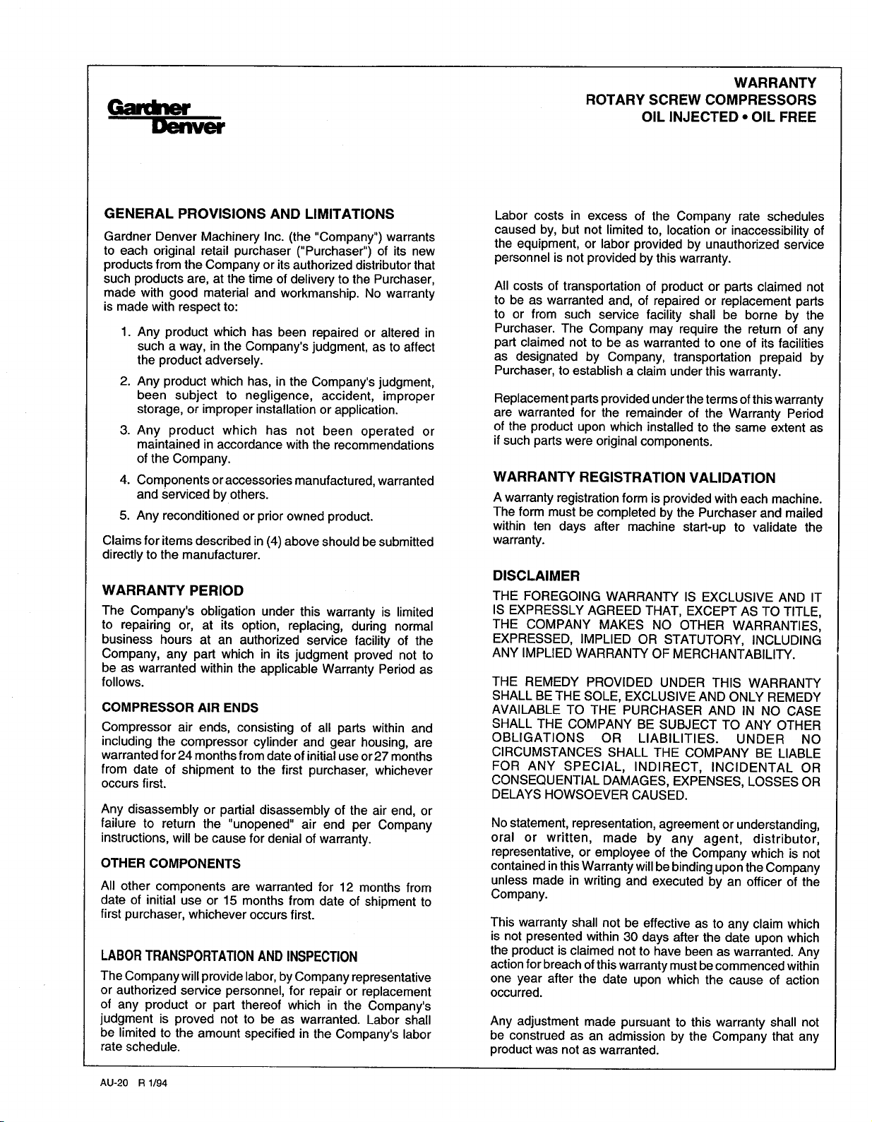
WARRANTY
ROTARY SCREW COMPRESSORS
OIL INJECTED - OIL FREE
GENERAL PROVISIONS AND LIMITATIONS
Gardner Denver Machinery Inc. (the “Company”) warrants
to each original retail purchaser (“Purchaser”) of its new
products from the Company or its authorized distributor that
such products are, at the time of delivery to the Purchaser,
made with good material and workmanship. No warranty
is made with respect to:
1.
Any product which has been repaired or altered in
such a way, in the Company’s judgment, as to affect
the product adversely.
2.
Any product which has, in the Company’s judgment,
been subject to negligence, accident, improper
storage, or improper installation or application.
3.
Any product which has not been operated or
maintained in accordance with the recommendations
of the Company.
4.
Components or accessories manufactured, warranted
and serviced by others.
5.
Any reconditioned or prior owned product.
Claims for items described in (4) above should be submitted
directly to the manufacturer.
WARRANTY PERIOD
The Company’s obligation under this warranty is limited
to repairing or, at its option, replacing, during normal
business hours at an authorized service facility of the
Company, any part which in its judgment proved not to
be as warranted within the applicable Warranty Period as
follows.
COMPRESSOR AIR ENDS
Compressor air ends, consisting of all parts within and
including the compressor cylinder and gear housing, are
warranted for 24 months from date of initial use or27 months
from date of shipment to the first purchaser, whichever
occurs first.
Any disassembly or partial disassembly of the air end, or
failure to return the “unopened” air end per Company
instructions, will be cause for denial of warranty.
OTHER COMPONENTS
All other components are warranted for 12 months from
date of initial use or 15 months from date of shipment to
first purchaser, whichever occurs first.
LABORTRANSPORTATIONANDINSPECTION
The Company will provide labor, by Company representative
or authorized service personnel,
of any product or part thereof which in the Company’s
judgment is proved not to be as warranted. Labor shall
be limited to the amount specified in the Company’s labor
rate schedule.
for repair or replacement
Labor costs in excess of the Company rate schedules
caused by, but not limited to, location or inaccessibility of
the equipment, or labor provided by unauthorized service
personnel is not provided by this warranty.
All costs of transportation of product or parts claimed not
to be as warranted and, of repaired or replacement parts
to or from such service facility shall be borne by the
Purchaser. The Company may require the return of any
part claimed not to be as warranted to one of its facilities
as designated by Company, transportation prepaid by
Purchaser, to establish a claim under this warranty.
Replacement parts provided under the terms of this warranty
are warranted for the remainder of the Warranty Period
of the product upon which installed to the same extent as
if such parts were original components.
WARRANTY REGISTRATION VALIDATION
A warranty registration form is provided with each machine.
The form must be completed by the Purchaser and mailed
within ten days after machine start-up to validate the
warranty.
DISCLAIMER
THE FOREGOING WARRANTY IS EXCLUSIVE AND IT
IS EXPRESSLY AGREED THAT, EXCEPT AS TO TITLE,
THE COMPANY MAKES NO OTHER WARRANTIES,
EXPRESSED, IMPLIED OR STATUTORY, INCLUDING
ANY IMPLIED WARRANTY OF MERCHANTABILITY.
THE REMEDY PROVIDED UNDER THIS WARRANTY
SHALL BE THE SOLE, EXCLUSIVE AND ONLY REMEDY
AVAILABLE TO THE PURCHASER AND IN NO CASE
SHALL THE COMPANY BE SUBJECT TO ANY OTHER
OBLIGATIONS OR LIABILITIES. UNDER NO
CIRCUMSTANCES SHALL THE COMPANY BE LIABLE
FOR ANY SPECIAL, INDIRECT, INCIDENTAL OR
CONSEQUENTIAL DAMAGES, EXPENSES, LOSSES OR
DELAYS HOWSOEVER CAUSED.
No statement, representation, agreement or understanding,
oral or written, made by any agent, distributor,
representative, or employee of the Company which is not
contained inthis Warranty willbe binding upon the Company
unless made in writing and executed by an officer of the
Company.
This warranty shall not be effective as to any claim which
is not presented within 30 days after the date upon which
the product is claimed not to have been as warranted. Any
action for breach ofthis warranty must be commenced within
one year after the date upon which the cause of action
occurred.
Any adjustment made pursuant to this warranty shall not
be construed as an admission by the Company that any
product was not as warranted.
AU-20 R 1/94
 Loading...