

Gardner Bender Sidewinder B2555RIG, Sidewinder B2555EMT, Sidewinder B2555 Series, Sidewinder B2555IMC, B2555PVC Instruction Sheet
Page 1
1.0 Safety Symbol Definitions . . . . . . . . . . . . . . . . . . . .2
2.0 Warnings . . . . . . . . . . . . . . . . . . . . . . . . . . . . . . . . .2
3.0 Bender Features . . . . . . . . . . . . . . . . . . . . . . . . . . .3
4.0 Specifications . . . . . . . . . . . . . . . . . . . . . . . . . . . . .3
5.0 Special Features . . . . . . . . . . . . . . . . . . . . . . . . . . .3
6.0 Model Information . . . . . . . . . . . . . . . . . . . . . . . . . .3
7.0 Shoe Groups . . . . . . . . . . . . . . . . . . . . . . . . . . . . . .4
7.1 Rigid . . . . . . . . . . . . . . . . . . . . . . . . . . . . . . . . .4
7.2 IMC . . . . . . . . . . . . . . . . . . . . . . . . . . . . . . . . . .4
7.3 EMT . . . . . . . . . . . . . . . . . . . . . . . . . . . . . . . . . .4
7.4 PVC . . . . . . . . . . . . . . . . . . . . . . . . . . . . . . . . . .4
8.0 Bending Radius Chart . . . . . . . . . . . . . . . . . . . . . . .4
9.0 General Bending Instructions . . . . . . . . . . . . . . . . .5
9.1 Mounting Support Rollers and Support Units . . . .5
10.0 Bending Instructions for
1
⁄ 2", 3⁄ 2", 1", 11⁄ 4"
EMT, IMC, and Rigid . . . . . . . . . . . . . . . . . . . . . . . .6
10.1 1
1
⁄ 2" & 2" EMT & IMC Conduit . . . . . . . . . . . . . .6
11.0 Squeeze Adjustment for 11⁄ 2" & 2" EMT and
IMC Support Roller Units . . . . . . . . . . . . . . . . . . . . .7
12.0 Maintenance Instructions . . . . . . . . . . . . . . . . . . . . .8
12.1 Gear Box Oil . . . . . . . . . . . . . . . . . . . . . . . . . . .8
12.2 Chain Tensioner #60 Chain (Front) . . . . . . . . . .8
12.3 Chain Tensioner #40 Chain (Rear) . . . . . . . . . .8
13.0 Stub-up Bending Information and Charts . . . . . . . .8
14.0 Offset Bending Information and Charts . . . . . . . . . .9
RPS-0151 Rev. A 06/04
Instruction Sheet
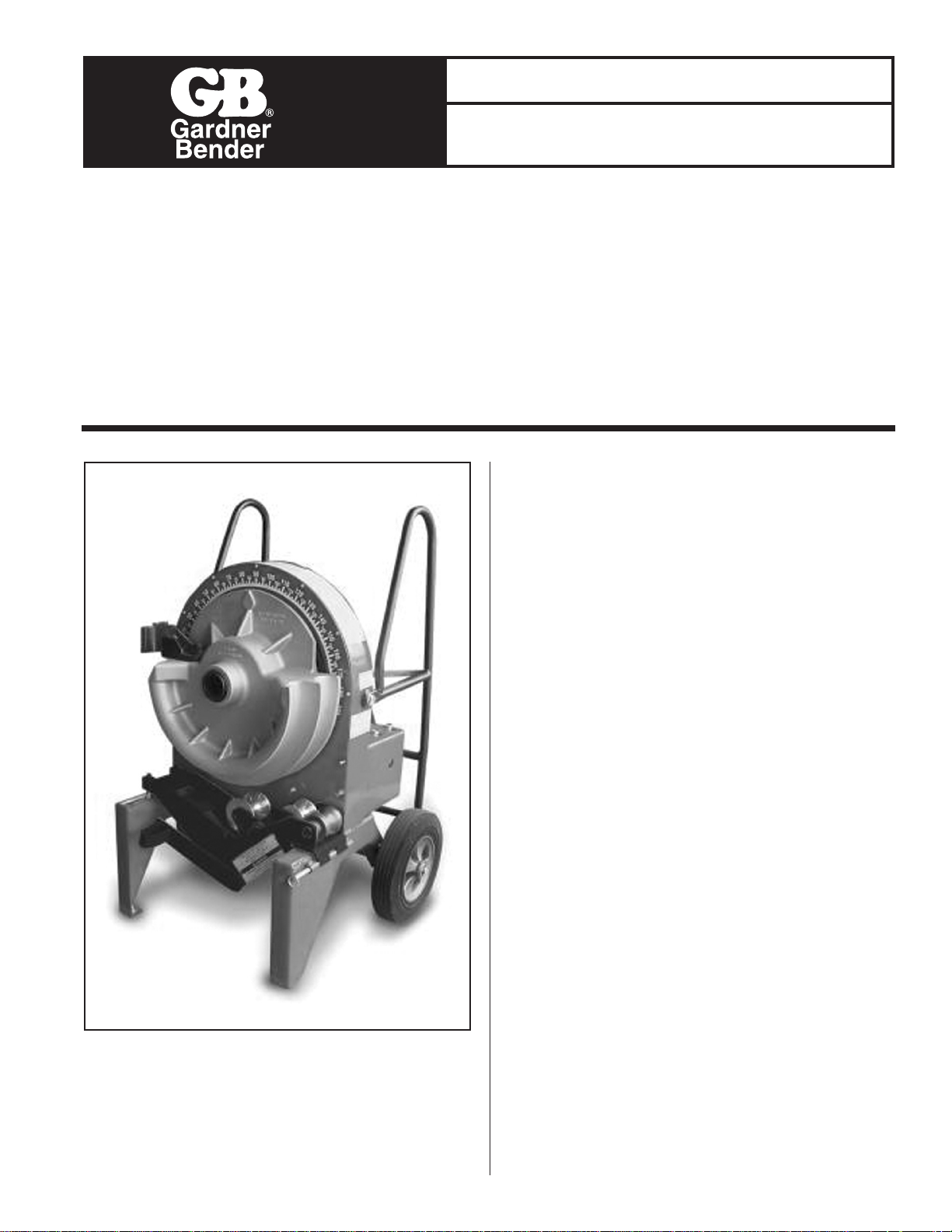
B2555 Electric Sidewinder
®
Bender
IMPORTANT RECEIVING INSTRUCTIONS
Visually inspect all components for shipping damage. If shipping damage is found, notify carrier at once. Shipping damage is NOT
covered by warranty. The carrier is responsible for all repair and replacement costs resulting from damage in shipment.
SAFETY ISSUES
IMPORTANT – USER SAFETY AND PROTECTION: In setting up systems to fit your operations, care must be taken to select the
proper components and design to insure appropriate that all safety measures have been taken to avoid the risk of personal injury
and property damage from your application or system.
GARDNER BENDER IS NOT RESPONSIBLE FOR DAMAGE OR INJURY CAUSED BY UNSAFE USE, MAINTENANCE OR THE
APPLICATION OF ITS PRODUCTS. Please contact Gardner Bender for guidance when you are in doubt as to the proper safety
precautions to be taken in designing and setting up your particular application.
B2555 Electric Sidewinder®Bender
Page 2
2
1.0 SAFETY SYMBOL DEFINITIONS
The symbol below is used to call your attention to instructions
concerning your personal safety. Watch for these symbols.
They point out important safety precautions. They mean
“ATTENTION! Become alert. Your personal safety is
involved.” Read the message that follows and be alert to the
possibility of personal injury or death.
Is serious but less inevitable. There is some probability
that death, severe bodily injury or major property
damage could result.
Is less serious but still demands attention. Indicates a
hazard which may result in minor injury or property
damage.
2.0 WARNINGS
This section contains information for your protection,
safety and quick reference. When using an electrical
appliance basic precautions should always be followed,
including the following.
Read all Instructions before using the B2555
Sidewinder
®
Bender.
Never operate this Bender in an explosive atmosphere.
Never operate the Bender in wet or damp locations.
DO NOT expose the Bender to rain.
Never use an extension cord longer than 100 feet.
Never alter this equipment, doing so will void this warranty.
Never wear loose clothing while operating the Bender.
Never stand on tool. Serious injury could occur if the tool
is tipped or if the bending shoe is unintentionally contacted.
Never leave tool running unattended. Turn power off.
Do not leave tool until it comes to a complete stop.
Never force tool. If bending shoe will not turn, STOP unit
and unplug before checking for any obstructions.
Always use 120 V AC, 20 AMP ground fault protected
receptacle for power supply.
Always inspect power cord before using Bender. Replace
damaged or worn cords.
Always wear approved safety glasses when the bender is
in operation.
Always disconnect the Bender before servicing or
changing shoes, attachments or supports, and when not
in use.
Always inspect the Bender before operating. Replace
any damaged, missing or worn parts.
Always use 12-gauge 20 AMP extension cords that have
three prong grounding type plugs and three-hole
receptacles that accept the Bender’s plug.
Always keep hands and feet away from pinch points
such as bending shoes, rollers and conduit when Bender
is in use.
Always keep conduit under control when bending.
Always keep the path of the bending conduit clear of
obstructions. Make sure all obstacles are clear of the
bending path BEFORE you bend the conduit.
Always use the appropriate shoe groove and roller
support for the type and size of conduit to be bent.
Always use the Bender in a dry, well lit area. Always
maintain Bender with care. Keep Bender clean for best
and safest performance.
Always make sure switch is in the off position
before plugging in. This will reduce the risk of
unintentional starting.
Always use recommended accessories. Consult this
manual for recommended accessories. The use of
improper accessories may cause risk of injury.
Always check for damaged or worn parts. Before further
use of the tool a guard or other part that is damaged
should be carefully checked to determined that it will
operate properly and perform its intended function.
Check for alignment of moving parts, binding of moving
parts, breakage of parts, mounting and any other
conditions that may affect its operation. A part that is
damaged should be properly repaired or replaced.
WARNING
WARNING
!
Page 3
Always make bender childproof with lockouts, master
switches or by unplugging unit.
Always use right tool. Don’t force tool or attachment to
do a job for which it was not designed.
Always wear proper apparel. Do not wear loose clothing,
gloves, neckties, rings, bracelets, or other jewelry which
may get caught in moving parts. Non-slip footwear is
recommended. Wear protective hair covering to contain
long hair.
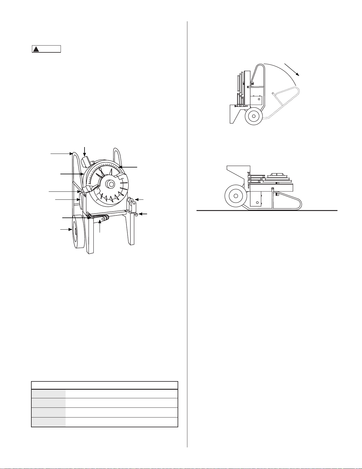
3.0 BENDER FEATURES
1. Bending Degree Scale - easy to read for exact bends
2. Support Rollers - for supporting the pipe during bending.
(Rigid set pictured.)
3. Hinge Pin - for securing the support rollers.
4. 12 Inch Wheels - for easy mobility.
5. D.C. Motor - quiet and strong.
6. Bending Instructions Decal - easy to read for
quick reference.
7. Remote Pendant - with 6 foot cord. (Bend and unload
from pendant.)
8. Handrail Bolt - Remove this bolt from both sides and
handles will hinge out of way to complete a off-set bend.
9. Large Handles - Protects the back of bender and enables
the bender to be used horizontally. (Can also be moved for
off-set bends.)
4.0 SPECIFICATIONS
5.0 SPECIAL FEATURES
The B2555 Series Benders have a unique feature for
the removal of the handles during an off-set Bend. See Figure
2. When creating back-to-back bends, the removal of the
handle may be necessary.
The B2555 Series Bender may also be used in a horizontal
position for special bends. The Bender can operate in this
position as efficiently as it does in the upright position. See
Figure 3.
6.0 MODEL INFORMATION
When equipped with the appropriate shoe group, the B2555
POWER UNIT is designed for bending:
• 1⁄ 2" through 2" Rigid conduit
• 1⁄ 2" through 2" EMT conduit
•
1
⁄ 2" through 2" IMC conduit
• 1⁄ 2" through 2" 40 mil PVC Coated Rigid conduit
• 1⁄ 2" through 2" schedule 40 steel pipe
No modification to the B2555 POWER UNIT is required to
accommodate these shoes or rollers. No tools are required to
install or remove these shoes and rollers. The B2555 BENDER
is NOT recommended for bending any steel quality above
schedule 40.
MODELS
B2555 Electric Bender Power Unit only, without shoes
and roller supports.
B2555RIG Electric Bender Unit with shoes and roller
supports for
1
⁄ 2" through 2" rigid conduit and pipe
and 1⁄ 2" thought 11⁄ 4" IMC conduit.
B2555EMT Electric Bender with shoes and roller supports for
1
⁄ 2" through 2" EMT conduit.
B2555IMC Electric Bender with shoes and roller supports for
1
⁄ 2" through 2" IMC conduit.
B2555PVC Electric Bender with shoes and roller supports for
1
⁄ 2" through 2" PVC coated conduit.
Figure 1. B2555 Electric Sidewinder®Bender
1
7
9
6
8
5
3
3
2
2
4
Figure 3. Horizontal Position
3
Figure 2. Handle Removal
B2555 Sidewinder®Bender
Width 291⁄ 2''
Length 241⁄ 2''
Height 42"
Weight 270 lbs. Power Unit Only w/o shoes
CAUTION
CAUTION
!
Page 4

7.0 SHOE GROUPS
7.1 RIGID
BRIG-52 - For bending 1⁄ 2'' thru 2'' Rigid Steel Conduit,
1
⁄ 2'' thru 11⁄ 4'' IMC Conduit and 1⁄ 2'' - 2'' Schedule 40 Pipe
7.2 IMC
BIMC-52 - For bending 1
1
⁄ 2'' thru 2'' IMC
7.3 EMT
BEMT-52 - For bending
1
⁄ 2'' thru 2'' (Thinwall)
7.4 PVC
BPVC-52 - For bending
1
⁄ 2'' thru 2'' 40 Mil PVC Coated Rigid
8.0 Bending Radius Chart
In the event of a malfunction or breakdown, grounding
provides a path of least resistance for electric current to
reduce the risk of electric shock. This tool is equipped with
an electric cord having an equipment-grounding conductor
and a grounding conductor and a grounding plug. The plug
must be plugged into a matching outlet that is properly
installed and grounded in accordance with all local codes
and ordinances.
Do not modify the plug provided - if it will not fit the
outlet, have the proper outlet installed by a qualified
electrician.
Improper connection of the equipment-grounding
conductor con result in a risk of electric shock. The
IMC
Part # Description ID #
IS-15 11⁄ 2'' Bending shoe 1
IS-2 2'' Bending Shoe 2
ISR-152 11⁄ 2'' - 2'' IMC Roller Support Unit 3
BX-1 Metal Storage Box (not shown)
Figure 5. BIMC-52 - IMC Shoe Group
Figure 6. BEMT-152 - EMT Shoe Group
EMT
Part # Description ID #
ES-5125
1
⁄ 2'' thru 11⁄ 4'' Bending shoe 1
ESR-5125
1
⁄ 2'' thru 11⁄ 4'' EMT Support 2
ES-15 11⁄ 2'' Bending Shoe 3
ES-2 2'' Bending Shoe 4
ESR-152 11⁄ 2''-2'' EMT Roller Support 5
BX-1 Metal Storage Box (not shown)
1
1
2
2
3
3
4
5
Conduit Centerline Bending Radius
Size
1
⁄ 2''
3
⁄ 4'' 1'' 11⁄ 4'' 11⁄ 2'' 2''
EMT 41⁄ 4
''
5
3
⁄ 8
''
6
3
⁄ 4
''
8
3
⁄ 4
''
8
9
⁄ 32
''
9
3
⁄ 16
''
IMC - - - - 89⁄ 32
''
9
3
⁄ 16
''
RIGID 4
3
⁄ 8
''
4
1
⁄ 2
''
5
3
⁄ 4
''
7
1
⁄ 4
''
8
1
⁄ 4
''
9
1
⁄ 2
''
Figure 7. BPVC-52 - PVC Shoe Group
1
2
3
4
4
PVC
Part # Description ID #
PVS-5125
1
⁄ 2'' thru 11⁄ 4'' Bending shoe 1
PVR-5125
1
⁄ 2'' thru 11⁄ 4'' Roller Support 2
PVS-152 11⁄ 2'' and 2'' Bending Shoe 3
PVR-152 11⁄ 2'' and 2'' Roller Support 4
BX-1 Metal Storage Box (not shown)
1
2
3
4
Figure 4. BRIG-52 - RIGID Shoe Group
RIGID
Part # Description ID #
RS-5125
1
⁄ 2'' thru 11⁄ 4'' Bending Shoe 1
RSR-5125 1⁄ 2'' thru 11⁄ 4'' Roller Support 2
RS-152 11⁄ 2'' and 2'' Bending Shoe 3
RSR-152 1
1
⁄ 2'' and 2'' Roller Support 4
Page 5

conductor with insulation having an outer surface that is
green with or without yellow stripes is the equipmentgrounding conductor. If repair or replacement of the
electric cord or plug is necessary, do not connect the
equipment-grounding conductor to a live terminal.
Check with a qualified electrician or service personnel it
the grounding instructions are not completely
understood, or if in doubt as to whether the tool is
properly grounded.
Use only 3-wire extension cords that have 3-prong
grounding plugs and 3-pole receptacles that accept the
tool’s plug.
Repair or replace damaged or worn cord immediately.
This tool is intended for use on a circuit that has an
outlet that looks like the one illustrated in Figure 8. The
tool has a grounding plug that looks like the plug
illustrated in Figure 9.
9.0 General Bending Instructions
Mounting Bending Shoes
Choose desired shoe size and type (Rigid, IMC, EMT, or 40
Mil PVC Coated Rigid) and slide shoe onto the main drive
sprocket shaft. See Figure 10. Next, align the four drive studs
on the back of the shoe with the four holes in the main drive
sprocket. Push the shoe onto the main drive sprocket shaft.
See Figure 11.
9.1 MOUNTING SUPPORT ROLLERS AND SUPPORT
UNITS
Choose the desired support roller or support unit for
corresponding shoe size and type (Rigid, IMC, EMT, or 40 mil
PVC coated Rigid.) The appropriate size and type of support
MUST be used with the corresponding shoe size and type.
Mount the support roller or support unit on the right leg of the
bender as you face the unit. Secure the support roller or
support unit with the quick release hinge pin. See Figure 12.
GREENLEE
®
- Bending shoes and attachment from
GREENLEE®555 R, E, I (Rigid, EMT, IMC) and 40 mil PVC
coated Rigid Benders with serial number PL and AAJ will fit
the B2555 Sidewinder®Bender. All B2555 Sidewinder
®
Bending shoes and attachments will fit GREENLEE 555 R, E,
I Benders with PL and AAJ serial numbers.
ENSLEY - No modifications are needed to mount the B2555
Sidewinder
®
Rigid shoes to the ENSLEY E-969.
Current Tools®- Bending shoe and attachments from Current
Figure 8. 3-Prong Outlet (20 A)
Sprocket Shaft
Main Drive
Sprocket
Drive Studs
Bending Shoe
Mounting Holes
Main Drive Sprocket
Figure 11. Mounting Bending Side View
5
Figure 10. Mounting Bending Front View
Figure 12. Mounting Support
Figure 9. 3-Prong Plug (Nema 5-20)
Page 6

Tools®77 Bender (Rigid, EMT, IMC, and PVC coated) will fit
the B2555 Sidewinder®.
GREENLEE®and 555®are registered trademarks of
GREENLEE/Textron.
ENSLEY and E-969 are trademarks of the Rothenberger Group.
10.0 BENDING INSTRUCTIONS, FOR
1
⁄ 2", 3⁄ 4", 1", 11⁄ 4"
EMT, IMC, AND RIGID
Never operate this Bender in an explosive atmosphere.
Injury or Death may occur.
1. Be sure to match the appropriate shoe with its
corresponding support unit. Attach the support using the
hinge pin. See Figure 12.
2. Mark pipe or conduit at desired length.
NOTE: A 2'' minimum dimension is required to eliminate
flattening the end of the pipe/conduit. See Figure 13.
NOTE: Stub-Up and offset dimensions can be found on the
Bending Charts on Pages 8 to 9 of this manual or on the
bending instructions decal on top of each Bender.
3. Rotate the bending shoe 5 to 10 degrees below the 0
(zero) degree setting, as shown in Figure 14. Place
Bending mark in line with front edge of shoe hook.
4. After marking the pipe/conduit, place it into the bender.
See Figure 14. The pipe/conduit should slide over the
correct size support unit, through the shoe groove and into
the hook. The Bending mark should be at the front
(OUTSIDE) edge of the hook. See Figure 14.
5. Using the remote hand unit (pendant) place the
“Bend/Unload” switch in the “bend” position. Press the
“Jog” button and advance the Bender. Be sure to check the
alignment of the bending mark as the rotating shoe locks
the pipe/conduit into position. Advance the Bender shoe to
the desired degree of bend. When the pointer on the shoe
reaches the desired degree of bend, release the “Jog”
button and the Bender will stop. See Figure 15.
NOTE: Due to springback in pipe/conduit, some over bending
is necessary to achieve the desired degree of bend. See page
8 and 9, or the bending instruction decal on the top of each
Bender for approximate springback compensation figures.
6. To release the pipe/conduit, place the “Bend/Unload”
switch in the “Unload” position. Press the “Jog” button and
reverse the shoe far enough to stop and drop the support
unit. See Figure 15. The pipe/conduit can now be removed.
NOTE: The pipe/conduit should be under control
when unloading.
Failure to return to zero to remove conduit may result in
injury or Death.
10.1 1
1
⁄ 2" & 2" EMT & IMC CONDUIT:
1. See "General Bending Instructions" for mounting shoes
and support units. Be sure to match the appropriate shoe
with its corresponding support unit.
NOTE: The outside roller on the 1
1
⁄ 2" - 2" IMC support unit is
metal See Figure 16. The outside roller on the 11⁄ 2" - 2" EMT
support unit is urethane. See Figure 17.
Figure 13. Bending Mark
Figure 14. Bending 5 to 10 Degrees
0
Hook
10 Degrees
10
Bending Mark
2
''
Min.
Bending Mark
Figure 15. Front View
Steel
Roller
Figure 17. Urethane Roller
Urethane
Roller
Figure 16. Steel Roller
6
WARNING
WARNING
!
Page 7

7
2. Mark the conduit to the desired length. Note that a 2"
minimum dimension is required to eliminate flattening the
end of the conduit. See Figure 18.
NOTE: “Stub-Up” and “Offset” dimensions can be found on
the bending charts on pages 8 to 9 of this manual or on the
bending instruction decal on the top of each Bender.
3. Rotate the bending shoe 5 to 10 degrees below the
0 degree setting. See Figure 14.
4. After marking the conduit, place it into the Bender. See
Figure 19. The conduit should slide over the support rollers
and through the shoe groove and into the hook. The
bending mark should be at the front (outside) edge of the
hook. See Figure 19.
NOTE: The appropriate size and type of support roller MUST
be used with the corresponding shoe size and type.
5. Step on the “Engaging Pedal” which will raise the proper
rollers to come in contact with the conduit. See Figure 19.
6. Keep foot pressure on the engaging pedal and push the
Bend/Unload switch to the “Bend” position. Then press the
“Jog” button. The conduit will pull the support rollers
assembly against the stop. Foot pressure can then be
removed from the engaging pedal. Be sure to check the
alignment of the bending mark as the rotating shoe locks
the conduit into position.
Advance the Bender shoe to the desired degree of bend.
When the pointer on the shoe reaches the desired degree
of bend, release the “Jog” button and the Bender will stop.
See Figure 20.
NOTE: Due to springback in pipe/conduit, some overbending
is necessary to achieve the desired degree of bend. See
page 8 and 9, or the bending instruction decal on top of each
Bender for approximate springback compensation figures.
7. To release the conduit, place the Bend/Unload switch in
the “Unload” position. Press the “Jog” button and reverse
the shoe. The support rollers will then drop, allowing
removal of the conduit.
Note that the pipe/conduit should be under control when
unloading. Failure to do this may result in injury or death.
8. After removal of the conduit, inspect it for wrinkling or
excessive side marks. If these conditions occur refer to the
“Squeeze Adjustment Procedure”.
11.0 SQUEEZE ADJUSTMENT FOR 11⁄ 2" & 2" EMT
AND IMC SUPPORT ROLLER UNITS
The B2555 Sidewinder®has a Squeeze Adjustment feature if
wrinkling or side marking becomes a problem during the
bending process. This feature allows you to increase or
decrease the amount of pressure applied to the conduit
during bending, thereby eliminating these problems.
1. If wrinkling occurs, pressure against the conduit during the
bending process must increase. To increase the squeeze
(pressure), loosen both sets of screws and turn both
adjusting bolts one-half turn clockwise. Tighten both set
screws and bend one piece of conduit to test the
adjustment. If wrinkling still occurs, repeat the procedure.
NOTE: Both adjusting bolts must be in contact with the
Bender frame. See Figure 22.
2. If side marking occurs, or loading IMC or EMT is a
problem, pressure against the conduit during the bending
process must be decreased. To decrease the squeeze
Figure 18. Bending Mark
2''
Min.
Bending Mark
Figure 19. Engaging Pedal
Conduit
Step
Engaging Pedal
Engaging
Peddle
Figure 20. Front View - Desired Bend Degree
Figure 22. Adjusting Bolts
5
⁄ 8''
Set Screw
Adjusting
Bolt
Left Leg of
Bender Frame
Starting Location
of Adjusting Bolt
Page 8

(pressure ), loosen both set screws and turn both adjusting
bolts one-half turn counterclockwise. Tighten both set
screws and bend one piece of conduit to test the adjustment.
If side marking still occurs, repeat the procedure.
NOTE: Both adjusting bolts must be in contact with
bender frame.
12.0 MAINTENANCE INSTRUCTIONS
12.1 GEAR BOX OIL
Always disconnect power supply before removing any
guards or covers and before servicing this bender.
Failure to do so may result in serious injury or death.
The Gear Box is filled with oil at the factory and should not
require periodic flushing. If the Gear Box is opened for repair,
flush with a light SAE #10 oil then run unit with no load for 3
minutes. Then, drain and refill the unit with 28 fluid ounces of
gear oil from the following list :
Amoco - Amoco Worm Gear Oil
Chevron - Cylinder Oil 460X
Exxon - CYLESSTIC TK460
Mobil - 600 W Cylinder Oil
Shell - Sun Gear Oil 7C
12.2 CHAIN TENSIONER # 60 CHAIN (FRONT)
To adjust front (# 60 Chain) Tension:
1. Remove front cover plate.
2. To increase tension on chain, loosen nut
“
A” and tighten nut “B”
3. To decrease tension on chain loosen nut “B” and tighten nut “A”
12.3 CHAIN TENSIONER # 40 CHAIN (REAR)
To adjust front ( # 40 Chain ) Tension:
1. Loosen 8 bolts (4 on top and 4 on bottom) that hold the gear
box in position.
2. To tighten, move the gear box to the left and re-tighten bolts.
3. To loosen, move the gear box to the right and re-tighten bolts.
NOTE: Be sure to keep the gear box and motor in line with
the bender.
13.0 STUB -UP B ENDI NG I NFOR MATION AND
CHARTS
To locate bending marks and springback of 15, 30, 45, 60,
and 90 degree bends for a desired stub:
1. Check chart A, B, or C for deduct length. Note that
minimum stub length is deduct length plus 2".
2. Measure and mark desired stub length on conduit (stub
length mark). Subtract “Deduct Length” from this mark and
make a second mark (bending mark). Place bending mark
at front edge of shoe hook. Check chart A, B, C for spring
back of desired degree of bend. Bender should be
advanced to this degree to obtain desired degree of bend.
NOTE: Springback figures are approximate. Minimum stub
length = deduct plus 2".
A
B
Figure 23. Front View - Tension Adjustment
Place Bending Mark in line with front edge of shoe hook
Stub Length Mark
Bending Mark
Stub Length
Chart A - Rigid Conduit/Schedule 40 Steel Pipe
Conduit Deduct
Springback
Size Length
15° 30° 45° 60° 90°
1
⁄ 2"8
1
⁄
2
"
20" 36
1
⁄
4
"
51
1
⁄
4
"
67
1
⁄
2
"
97
1
⁄
2
"
3
⁄ 4"8
1
⁄
2
"
16
1
⁄
4
"
31
1
⁄
4
"
46
1
⁄
4
"
61
1
⁄
4
"
92
1
⁄
2
"
1" 10
"
171⁄
2
"
32
1
⁄
2
"
47
1
⁄
2
"
63
3
⁄
4
"
93
3
⁄
4
"
11⁄ 4"12
3
⁄
4
"
17
1
⁄
2
"
32
1
⁄
2
"
47
1
⁄
2
"
63
3
⁄
4
"
95
"
11⁄ 2"14
1
⁄
4
"
18
3
⁄
4
"
33
3
⁄
4
"
48
3
⁄
4
"
65
"
95
"
2" 16
1
⁄
8
"
20
"
35"48
3
⁄
4
"
63
3
⁄
4
"
96
1
⁄
4
"
Chart B - EMT Conduit
Conduit Deduct
Springback
Size Length
15° 30° 45° 60° 90°
1
⁄ 2"7"161⁄4"321⁄
2
"
47
1
⁄
2
"
63
3
⁄
4
"
95
"
3
⁄ 4"8
7
⁄
8
"
17
1
⁄
2
"
33
3
⁄
4
"
48
3
⁄
4
"
63
3
⁄
4
"
95
"
1" 103⁄ 4
"
17
1
⁄
2
"
32
1
⁄
2
"
48
3
⁄
4
"
65
"
95
"
11⁄ 4"13
1
⁄
8
"
17
1
⁄
2
"
33
3
⁄
4
"
48
3
⁄
4
"
65
"
95
"
11⁄ 2"13
7
⁄
8
"
16
1
⁄
4
"
31
1
⁄
4
"
46
1
⁄
4
"
61
1
⁄
4
"
92
1
⁄
2
"
2" 15
3
⁄
8
"
17
1
⁄
2
"
33
3
⁄
4
"
48
3
⁄
4
"
63
3
⁄
4
"
95
"
Figure 24. Stub-up Bending Markings
Stub Length Mark
Bending Mark
Stub Length
Deduct Length
8
Page 9

14.0 OFFSET BENDING INFORMATION AND
CHARTS
1. Measure distance from end of conduit to start of bend and
mark conduit (“Mark 1”).
2. Refer to chart E for measurement “X” deduct this distance
from “Mark 1” and place “Mark 2” on conduit.
3. Refer to chart D for center to center distance between
marks. Measure this distance from “Mark 2” and place
“Mark 3” on conduit.
4. Layout of bends is now complete. Next, place “Mark 2” in
line with front edge of shoe hook and make first bend.
5. Rotate conduit 180°. Place “Mark 3” in line with front edge
of shoe hook and complete second bend.
NOTE: Figures are approximate.
To locate the center to center distance of offset bending marks
other than those listed in Chart D, use the following multipliers.
Multiply the height of offset desired by 3.86 on 15 degree
bends, 2 on 30 degree bends, and 1.4 on 45 degree bends.
NOTE: Figures are approximate.
Chart C - IMC Conduit
Conduit Deduct
Springback
Size Length
15° 30° 45° 60° 90°
1
⁄ 2"8
1
⁄
2
"
21
1
⁄4"371⁄
2
"
52
1
⁄
2
"
68
3
⁄
4
"
98
3
⁄
4
"
3
⁄ 4"8
1
⁄
2
"
17
1
⁄
2
"
32
1
⁄
2
"
47
1
⁄
2
"
63
3
⁄
4
"
93
3
⁄
4
"
1" 10
"
171⁄
2
"
32
1
⁄
2
"
47
1
⁄
2
"
63
3
⁄
4
"
95
"
11⁄ 4"12
3
⁄
4
"
18
3
⁄
4
"
33
3
⁄
4
"
48
3
⁄
4
"
65"96
1
⁄
4
"
11⁄ 2"13
3
⁄
4
"
17
1
⁄
2
"
33
3
⁄
4
"
48
3
⁄
4
"
63
3
⁄
4
"
95
"
2" 15
1
⁄
4
"
20
"
35"50
"
65"96
1
⁄
4
"
Mark 2
X
Front edge of shoe hook
Mark 1
Mark 3
Offset Height
Figure 25. Offset Bending Markings
Chart D - Offset Height
2 4 6 8 10 12 14 16 18 20 22
Max. Conduit Size
3
⁄
4
"
1
1
⁄
2
"
2
"
≤ 2
"
≤ 2
"
≤ 2
"
≤ 2
"
≤ 2
"
≤ 2
"
≤ 2
"
≤ 2
"
Center-to-center 7
3
⁄
4
"
15
7
⁄
16
"
23
3
⁄
16
"
30
15
⁄
16
"
38
5
⁄
8
"
46
3
⁄
8
"
54
1
⁄
16
"
61
13
⁄
16
"
69
9
⁄
16
"
77
1
⁄
4
" 85"
Max. Conduit Size -
3
⁄
4
"
1
"
1
1
⁄
2
"
2" ≤ 2
"
≤ 2
"
≤ 2
"
≤ 2
"
≤ 2
"
≤ 2
"
Center-to-center - 8" 12
"
16
"
20" 24" 28
"
32" 36" 40" 44"
Max. Conduit Size - -
1
⁄ 2
"
1
"
1
1
⁄
4
"
1
1
⁄
2
"
2
"
≤ 2
"
≤ 2
"
≤ 2
"
≤ 2
"
Center-to-center - - 8
1
⁄
2
"
115⁄
16
"
141⁄
8
"
1615⁄
16
"
1913⁄
16
"
225⁄
8
"
257⁄
16
"
281⁄
4
"
311⁄
8
"
15°
30°
45°
RPS-0151 Rev. A 06/04
PO Box 3241 • Milwaukee, WI 53201-3241 • 414-352-4160 • Fax 414-352-2377
6615 Ordan Drive • Mississauga, Ontario L5T 1X2 • 905-564-5749 • Fax 905-564-0305
WARRANTY: Gardner Bender warrants its product
against defects in workmanship and materials for 1
year from date of delivery to user. Chain is not
warranted. Warranty does not cover ordinary wear
and tear, abuse, misuse, overloading, altered products
or use of improper fluid.
WARRANTY RETURN PROCEDURE: When question
of warranty claim arises, send the unit to the nearest GB
Authorized Service Center for inspection, transportation
prepaid. Furnish evidence of purchase date. If the claim
comes under the terms of our warranty the Authorized
Service Center will REPAIR OR REPLACE PARTS
AFFECTED and return the unit prepaid.
PARTS AND SERVICE: For quality workmanship and
genuine Gardner Bender parts, select an Authorized
GB Service Center for your repair needs. Only
repairs performed by an Authorized Service Center
displaying the official GB Authorized sign are backed
with full factory warranty. Contact Gardner Bender
(414)352-4160 for the name of the nearest GB
Authorized Service Center.
REPAIR AND SERVICE INSTRUCTIONS: For repair service and parts contact your nearest Gardner Bender
Service Center. The Gardner Bender Service Center will provide complete and prompt service on all Gardner
Bender products.
9
Chart E
Size
1
⁄2''
3
⁄4'' 1'' 11⁄4'' 11⁄2'' 2''
“X” 3
1
⁄
16
''
3
1
⁄
16
''
3
1
⁄
16
''
4
''
4
1
⁄
4
''
4
1
⁄
2
''
Gardner
Bender
 Loading...