

Page 1
1.0 Description . . . . . . . . . . . . . . . . . . . . . . . . . . . . . .2
2.0 Safety Symbol Definitions . . . . . . . . . . . . . . . . . .2
3.0 Warnings . . . . . . . . . . . . . . . . . . . . . . . . . . . . . . .2
4.0 Grounding Instructions . . . . . . . . . . . . . . . . . . . . .3
5.0 Technical Specifications . . . . . . . . . . . . . . . . . . .3
6.0 Product Description . . . . . . . . . . . . . . . . . . . . . . .3
7.0 Use and Operation . . . . . . . . . . . . . . . . . . . . . . . .4
7.1 Blowing Line in Conduit . . . . . . . . . . . . . . . . .4
7.2 Preparation . . . . . . . . . . . . . . . . . . . . . . . . . .4
7.3 Selecting the Pull Lines . . . . . . . . . . . . . . . . .4
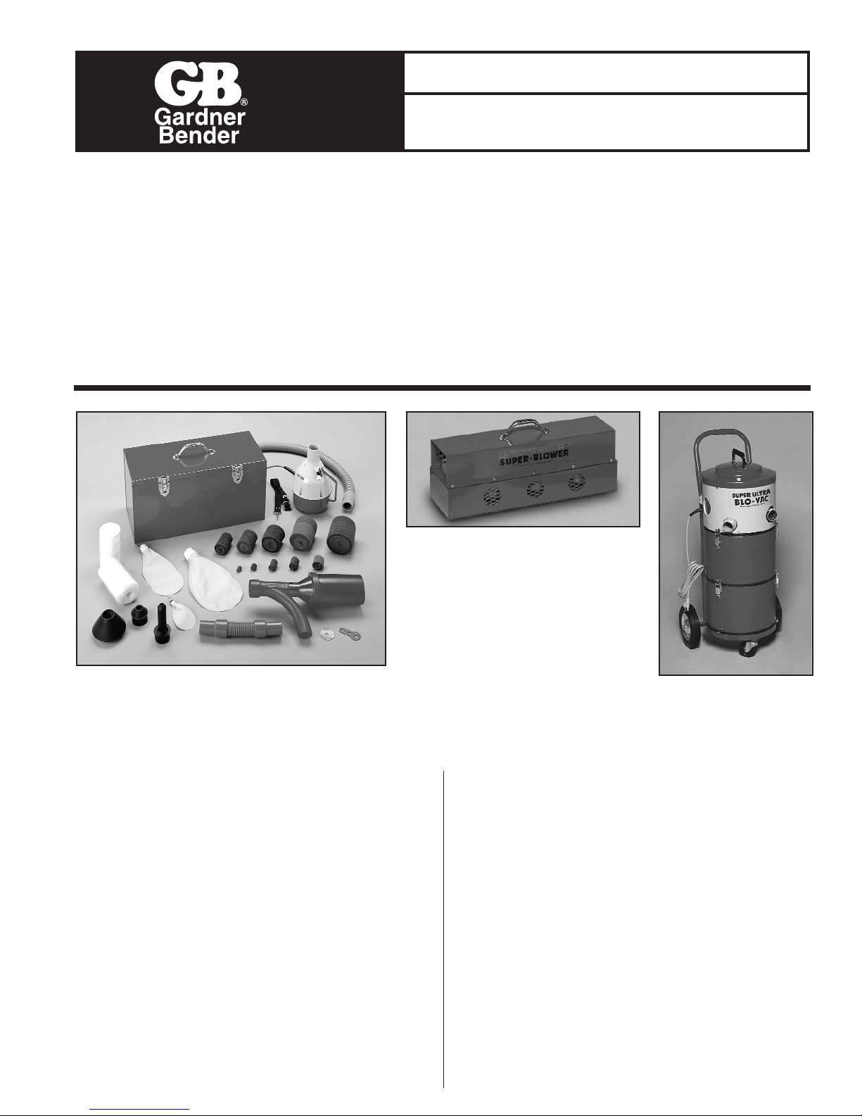
B3000 Blower for B60
B4500K Blower Kit
RPS-0106 01/02
Instruction Sheet
B4500K, B60, BV208DA
IMPORTANT RECEIVING INSTRUCTIONS
Visually inspect all components for shipping damage. If shipping damage is found, notify carrier at once. Shipping damage is NOT
covered by warranty. The carrier is responsible for all repair and replacement costs resulting from damage in shipment.
SAFETY ISSUES
IMPORTANT – USER SAFETY AND PROTECTION: In setting up systems to fit your operations, care must be taken to select the
proper components and design to insure appropriate that all safety measures have been taken to avoid the risk of personal injury
and property damage from your application or system.
GARDNER BENDER IS NOT RESPONSIBLE FOR DAMAGE OR INJURY CAUSED BY UNSAFE USE, MAINTENANCE OR THE
APPLICATION OF ITS PRODUCTS. Please contact Gardner Bender for guidance when you are in doubt as to the proper safety
precautions to be taken in designing and setting up your particular application.
7.4 Power Saver™ Line Packages . . . . . . . . . . .5
7.5 Tag-Along™ Line Packages . . . . . . . . . . . . .5
7.6 PL Series Pull Line . . . . . . . . . . . . . . . . . . . .5
7.7 Seal-Offs . . . . . . . . . . . . . . . . . . . . . . . . . . . .6
7.8 Line Carriers . . . . . . . . . . . . . . . . . . . . . . . . .7
7.9 Blowing or Vacuuming Thru Conduit . . . . . . .8
8.0 Maintenance . . . . . . . . . . . . . . . . . . . . . . . . . . .10
9.0 Jetline
®
Systems . . . . . . . . . . . . . . . . . . . . . . . .10
9.1 B4500K Line Shooter™ Blowing System . .11
9.2 B60 Super Blower™ System . . . . . . . . . . . .12
BV208DA Blo-Vac
™
Page 2
2
1.0 DESCRIPTION
The GB/JetLine®Blower and Blo-Vac™ Systems are low
pressure tools that deliver high volume air stream, which is
used to place pull line in most conduit from 1⁄2" to 6" diameter.
Blow-Vac™ systems are intended for commercial use only.
The systems are convenient to use in new and existing
construction. They require a 120 V, 60 Hz grounded power
source. See 5.0 Technical Specifications, GB/JetLine
®
Blowers Table and GB/JetLine®Blo-Vac™ Table.
The Blower or Blo-Vac™ System consists of four basic
components:
• The Power Unit – a high volume air or vacuum source.
• Hose and Seal-Off – to channel the air into the conduit and
form a seal at the conduit entrance.
• A Line Carrier – to serve as a movable object that supplies
the pulling force to install pull line in conduit.
• Pull Line – for pulling wire through the conduit, to pull rope
or cable for large or difficult runs.
A thorough understanding of all components and their
functions and operating precautions is essential for safe and
efficient use of the system.
Read and understand all the instructions before attempting to
use the system or blow line into conduit.
2.0 SAFETY SYMBOL DEFINITIONS
The symbol below is used to call your attention to instructions
concerning your personal safety. Watch for these symbols.
They point out important safety precautions. They mean
“ATTENTION! Become alert. Your personal safety is
involved.” Read the message that follows and be alert to the
possibility of personal injury or death.
DANGER: Indicates a high probability that death,
severe bodily injury or major property damage could result.
WARNING: Is serious but less inevitable. There is
some probability that death, severe bodily injury or
major property damage could result.
CAUTION: Is less serious but still demands
attention. Indicates a hazard which may result in minor
injury or property damage.
3.0 WARNINGS
This section contains information for your protection,
safety and quick reference. When using an electrical
appliance basic precautions should always be followed,
including the following.
Read all Instructions before using the Blo-Vac
™
System.
CAUTION: Do not leave the Blo-Vac™ when plugged
in. Unplug from outlet when not in use and
before servicing.
CAUTION: To reduce the risk of electrical shock: Do
not expose to rain. Store indoors.
CAUTION: Use only as described in this manual.
Use only manufacturer’s recommended attachments.
WARNING: Do not use with damaged cord or plug. If
the Blo-Vac™ is not working as it should, has been
dropped, damaged, or dropped in water, return it to a
service center.
CAUTION: Do not pull or carry by cord, use cord as
a handle, close a door on cord, or pull around sharp
edges or corners. Do not run the Blo-Vac
™
over cord.
Keep cord away from heated surfaces.
WARNING: Do not unplug by pulling on cord. To
unplug, grasp the plug, not the cord.
CAUTION: Do not handle plug or Blo-Vac
™
with
wet hands.
CAUTION: Do not put any object into openings. Do
not use with any opening blocked: keep free of dust, lint
and anything that may reduce air flow.
WARNING: Keep hair, loose clothing, fingers and all
parts of body away from openings and moving parts.
WARNING: Do not pick up anything that is burning
or smoking, such as cigarettes, matches, or hot ashes.
CAUTION: When used for vacuum clean-up, do not
use without filter bag in place.
CAUTION: Turn off switch before unplugging.
DANGER: Do not use to pick up flammable or
combustible liquids such as gasoline. Do not use in
areas where they are present.
WARNING: Use extra caution when working on a
ladder, elevated platforms, stairs, etc.
WARNING: Do not use the power unit in a manhole
— keep the power unit above ground.
DANGER: All GB/JetLine
®
conduit fishing Blo-Vac
™
systems are designed to force loose debris of all types
out of the conduit by means of a pressurized force.
Serious or critical injury may result to anyone struck by
high velocity debris or the line carrier. Warn all personnel
to stand clear of the conduit exit prior to pressurization
procedures or blowing line into the conduit.
CAUTION: GB/JetLine
®
Blo-Vac™Systems have
been designed specifically for fishing conduit. The
system, under certain field conditions, may be used to
remove debris or water from the conduit. The electric
motor is protected from liquid entering the fan area by a
float ball. If liquid is discharged, the float ball has been
defeated. Immediately unplug unit from power source
and check to make sure the float ball is functioning
properly and the sealing area is free of foreign matter.
DANGER: Failure to observe these instructions or
misuse of equipment could result in serious injury or
possible death.
Page 3
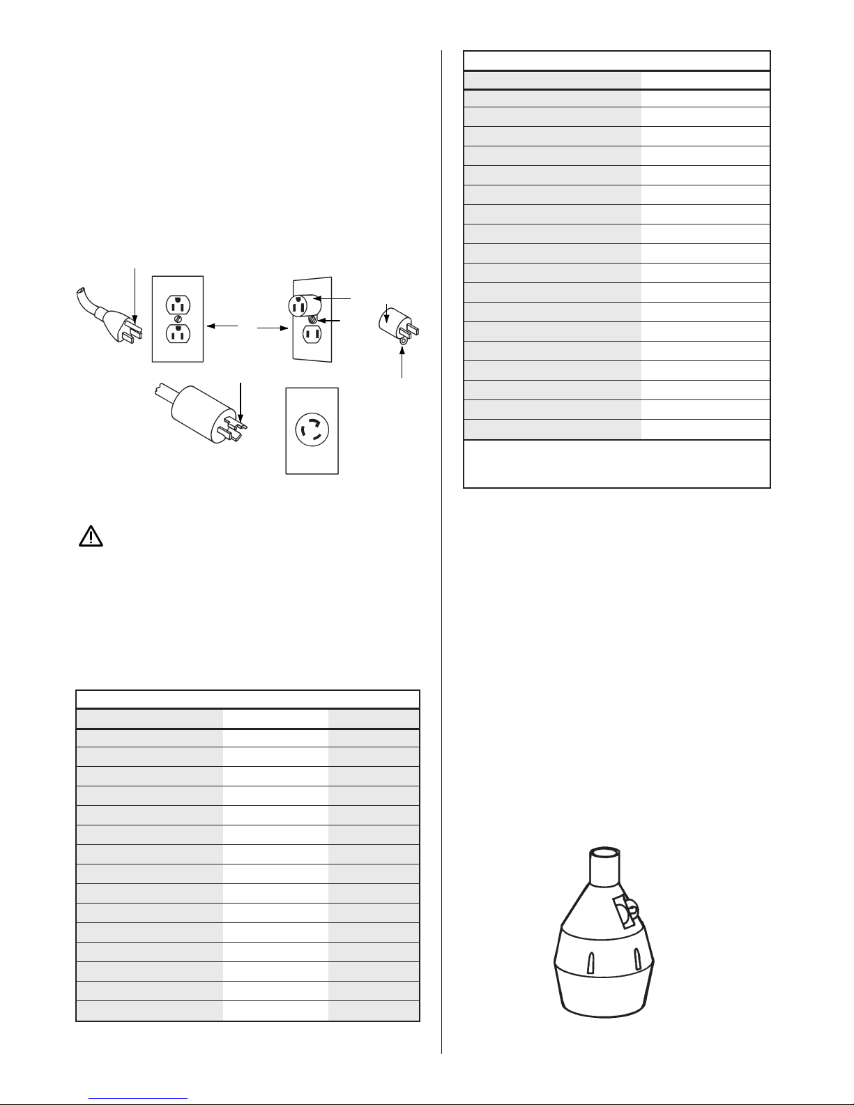
4.0. GROUNDING INSTRUCTIONS
The GB/JetLine®blowers and Blo-Vac™ systems require a
120 V, 60 Hz, 15 A circuit; with the exception of the B3000
power unit which requires a 120 V, 60 Hz, 30 A circuit; and
must be grounded. If the power unit should malfunction or
breakdown, grounding provides a path of least resistance for
the electrical current to reduce the risk of electrical shock.
These power units are equipped with a cord that has a
grounding conductor and grounding plug. The plug must be
inserted into an outlet that is properly grounded in
accordance with all codes and ordinances. See Figure 1.
CAUTION: Improper connection of the equipment
grounding conductor can result in a risk of electrical
shock. Check with a qualified electrician or service
person if you are in doubt as to whether the outlet is
properly grounded. Do not modify the plug provided with
the Blo-Vac™. If it will not fit the outlet, have the correct
outlet installed by a qualified electrician.
5.0 TECHNICAL SPECIFICATIONS
6.0 PRODUCT DESCRIPTION
GB/JetLine®Blowers and Blo-Vac™systems are designed to
provide a convenient means of installing pull line in a “sealed”
conduit. “Sealed” conduit for this purpose is considered EMT
conduit with compression type couplings, rigid conduit with
threaded joints, or PVC conduit with adhesive bonded joints.
Conduit with set screw type couplings does not effectively
seal joints and substantial air or vacuum loss occurs making it
difficult to maintain pressure or vacuum to place a line in
the conduit.
Blower Systems
GB/JetLine
®
supplies two blower systems; the B4500K Line
Shooter™ (for fishing from
1
⁄
2" through 4" trade size conduit)
and the B60 Super Blower™ for heavy duty work in conduit
from 21⁄2" through 6". See Figures 2 and 3.
B4500K Line Shooter
™
The B4500K Line Shooter™ conduit fishing kit is equipped
with a light weight 1261 Power Unit, three foot hose, shoulder
strap, power saver line packages, foam line carriers,
inflatables and accessories for fishing conduit from 1⁄2" through
4". Bulk pull line is not included with the kit.
3
Grounding Pin
Grounded
Outlet Box
Adapter
Metal
Screw
Tab for
Grounding Screw
Grounding
Blade
Figure 1. Grounding Methods
125 V
30 A
NEMA
L5-30R
GB/JetLine®Blowers
B4500K B60
Power Unit 1261 B3000
Voltage 120 120
Frequency 60 Hz 60 Hz
AMPS 7.50 23
In. Water Lift (sealed) 85-92 85-92
P.S.I. 3.31 3.31
CFM 90 270
No. of Motors 1 3
Impeller Stages (Fans) 2 2
Thermal Overload Yes Yes
Motor Type (Cooling) Flow Through Flow Through
Handling Portable Portable
Weight 7.5 lb 35 lb
Hose Dia. (Inch) 11⁄2 21⁄2
Length (Feet) 3 25
GB/JetLine®Blo-Vac™
BV208DA
Power Unit 1523
Voltage 120
Frequency 60 Hz
AMPS 13.8
Inches Water Lift (sealed)* 130-135
P.S.I.* 4.86
CFM 92
No. of Motors 1
Impeller Stages (Fans) 3
Thermal Overload No
Motor Type (Cooling) By-Pass
Handling Cart
Recovery Cap. (Gals) 9**
Height with Cart (Inch) 41
Motor Brush Life (Hours) 750
Weight 50 lb
Hose Dia. (Inch) 11⁄2
Length (Feet) 8
* Will vary with voltage and atmospheric conditions.
** When using recovery compartment and tool storage
compartment together.
Figure 2. 1261 Blower
Page 4
B60 Super Blower™
The B60 Super Blower™ was designed for use in long
underground single bore conduit from 2
1
⁄2" through 6". The
B3000 Power Unit must remain above ground for safety
reasons, and the 21⁄2" diameter x 25' long hose and seal-off
are used in the manhole. The portable triple motor power unit
provides a high volume of air to blow a line in large bore
conduit whether above ground or below ground.
Blo-Vac™ Systems
GB/JetLine
®
Blo-Vac™ Systems: BV208DA Super-Ultra
Blo-Vac™ provides blowing or vacuuming capabilities
for conduit fishing of
1
⁄2" through 6". These systems provide a
higher output pressure for more difficult runs. The water lift
capabilities of the Blo-Vac™ is the same for blowing or
vacuuming. See 5.0 Technical Specifications, GB/JetLine
®
Blo-Vac™Table.
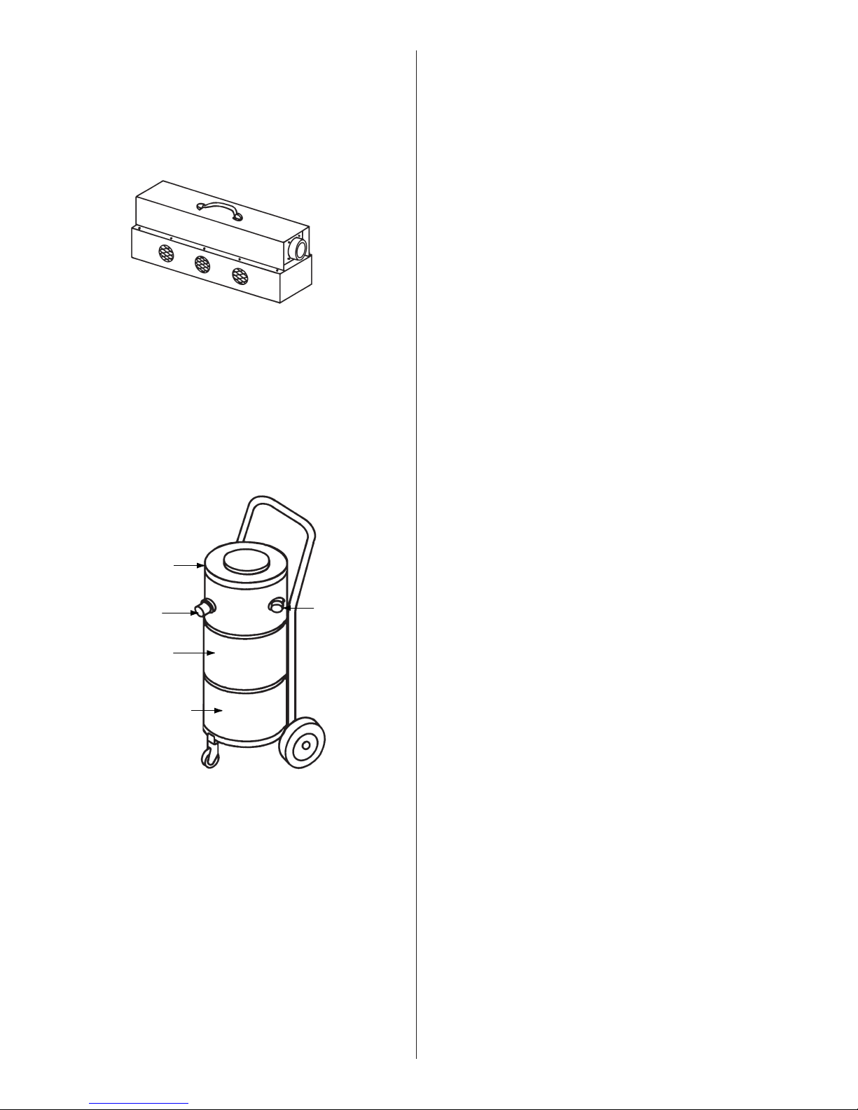
Each Blo-Vac™ system is cart mounted for easy transporting
around the job site. Each Blo-Vac™ unit has three
compartments which are easily separated. The top section is
the power unit, the center section is the recovery
compartment, and the bottom section is storage for
accessories. See Figure 4. The power unit and the recovery
compartment may be unlatched from the tool storage
compartment and used as a portable blower vacuum system.
All Blo-Vac™ systems are equipped with a 1
1
⁄2" diameter x 8'
long hose and seal-offs to fit
1
⁄2" through 6" conduit.
The BV208DA Super Ultra Blo-Vac™ has a powerful threestage motor fan section. The recovery capacity is 41⁄
2 gallons
expandable to 9 gallons by using the tool storage
compartment above the recovery compartment after
removing the false bottom. Housings are made of high
impact polypropylene.
7.0 USE AND OPERATION
The primary purpose of the GB/JetLine®Conduit Fishing
System is to place a pull line in the conduit by the quickest
and easiest means available. The GB/JetLine®Blower and
Blo-Vac™ systems are low pressure, high volume machines
that are easy and convenient to use.
7.1 Blowing Line in the Conduit
The GB/JetLine®Blower and Blo-Vac™ systems are
designed to blow line in a “sealed” conduit such as EMT
conduit with compression type couplings, rigid conduit with
threaded joints, or PVC conduit with adhesive bonded joints.
These types of conduit require very little effort to install a pull
line with the Blower or Blo-Vac™ system.
There are some conduit runs that will be difficult or impossible
to blow a line in, such as:
• Conduit containing hard packed sand, silt, debris
or concrete.
• Conduit containing water with a head greater than the
maximum water lift of the Blower or Blo-Vac™ system.
• Conduit with leaking or separated joints.
• Conduit with two sizes of duct connected by a reducer.
• Conduit with unsealed set screw couplings.
• Small diameter conduit of several hundred feet with
multiple bends.
Let Gravity Help
When blowing line in conduit of tall buildings or underground
duct, start at the highest elevation of the conduit entrance. In
underground duct; water may have accumulated in low points
of the run, and the blower may not be able to force it out.
Start at the highest point.
7.2 Preparation
It is helpful to know the purpose for which the line is to be
used once it has been blown into the conduit.This will aid the
user in selecting the appropriate line for the job.
Knowing the approximate length of the conduit run will
prevent selecting a line too short for the run. For example, if
lightweight pull line is being placed in
3
⁄4" conduit with a
estimated length of 195' to 200', select a 300'. Power Saver™
line package for the run. An alternate solution would be to
use a
3
⁄4" foam line carrier pulling bulk nylon line. Either
selection would insure an adequate length of line.
7.3 Selecting the Pull Line
It is not possible to foresee all conduit situations that may be
encountered, therefore, the following is presented as a guide
in selecting pull line. Determine which best fits the situation;
whether the line is to be used for conduit identification, pulling
in a larger line or rope, pulling in wire or for wire pulls at a
later date.
1. Identification of a conduit termination where multiple
conduit runs originate from a single location.
Recommended line: Power Saver™ Line Packages or
Bulk Nylon Line.
2. Placing a line in the conduit for use at a later date.
Recommended line: Small conduit
1
⁄2", 3⁄4" and 1" — Power
Saver™ Line Packages, Bulk Nylon Line or PL232 Pull
Line. Larger conduit 11⁄4" through 6" — Tag-Along™ Line
Packages, PL232 or PL235.
3. Pulling in larger line, rope or steel winch cable.
Recommended line: Small conduit — same as above.
Larger conduit PL232, PL235 or Poly Rope.
4. Pulling wire in conduit. Recommended line: PL232,
PL235 or Poly Rope.
4
Blower Outlet
Power Unit
Vacuum Inlet
Recovery Compartment
Tool Storage Compartment
Figure 4. Blo-Vac™
Figure 3. B3000 Super Blower
Page 5

7.4 Power Saver™ Line Packages
The Power Saver™ line package is the easiest and
most versatile line that can be installed in conduit. The selfcontained (no line carrier needed) 17 lb. breaking strength
nylon line package comes in different lengths sized for
1
⁄2", 3⁄4"
and 1" conduit. It dispenses a line as the package is blown or
vacuumed through the conduit. The line may be used for
identification of the conduit exit, pulling in a heavier pull line
(PL series pull line or small rope).
7.5 Tag-Along™ Line Packages
The Tag-Along™ line package must be used with a line
carrier (foam or inflatable) in 11⁄4" or larger conduit. The
increased package diameter and length prevents the package
from passing freely through or around bends in conduit less
than 1
1
⁄4". Once attached to the line carrier, the Tag-Along™
line package function and operation is similar to that of the
Power Saver™ package. Breaking strengths are 22 lbs.
Bulk Nylon Line
JetLine
®
bulk nylon line is fed into the conduit through the
seal-off feed through port. However, unlike the Power
Saver™ and Tag-Along™ package, bulk line packages
remain at the conduit entrance. Line is pulled into the conduit
by one of the JetLine
®
line carriers. Bulk nylon line is supplied
in 22 lb., 30 lb. and 100 lb. breaking strengths.
7.6 PL Series Pull Line
JetLine®linear stranded PL series pull lines are designed
specifically for conduit fishing. These lines are made of strong
polyolefin plastic that will not rust, rot or mildew. The coreless
wound roll of knot free pull line makes center dispensing from
the carton a convenient feature when feeding the pull line
directly into the conduit through the seal-off.
The PL Series are oval in shape and tend to flatten out in
bends. The flattened edges reduce the abrasive and cutting
effect in PVC conduit.
PL102 Pull Line - The 6500' roll of 190 lb. breaking strength
pull line is fiberlated polyolefin line (approx.
1
⁄8" in diameter).
PL232 Pull Line - The 6500' roll of 200 lb. breaking strength
pull line is oval in shape (approx. 3⁄32" x 5⁄32") will pass through
the feed through port of all JetLine®seal-offs.
PL235 Pull Line - The 2200' roll of 500 lb. breaking strength
pull line is oval in shape (approx. 1⁄8" x 5⁄16") will feed through
the port of Catalog No. B26 large Dial-A-Line™ seal-off body.
Figure 5. Power Saver™ Line Packages
Power Saver™ Line Packages
Part # Conduit Size Length
LP2150
1
⁄2" 150'
LP3200
3
⁄4" 200'
LP3300
3
⁄4" 300'
LP3450
3
⁄4" 450'
LP4200 1" 200'
LP4300 1" 300'
LP4450 1" 450'
Figure 6. Tag Along™ Line Packages
Tag-Along™ Line Packages
Part # Length Strength
LP2206T 400' 22 lbs
LP2208T 600' 22 lbs
LP2207T 800' 22 lbs
Figure 7. Bulk Nylon Line
Bulk Nylon Line
Part # Length Strength
LP1701 1000' 100 lbs
LP1702 2000' 30 lbs
LP1703 1400' 22 lbs
LP1707* 1350' 100 lbs
LP1722 2200' 90 lbs
* Wound on cardboard tube, not center dispensing.
Figure 8. Dispensing Carton and Bucket
PL-series Pull Line
Part # Length Strength
PL231 1000' 100 lbs
PL102 6500' 190 lbs
PL232 6500' 210 lbs
PL235 2200' 500 lbs
5
Page 6

Conduit Measuring Tape
JetLine
®
TT31 True Tape™ and ST40 Super True Tape™
provide an accurate means of measuring the length of
conduit runs already in place. Both are marked in
1' increments.
When measuring for wire length, measure from terminal to
terminal, not from end of conduit. See Conduit Measuring
Tape Table for allowances to be made for 90° bends, 45°
offsets, and panel boxes.
7.7 Seal-Offs
The GB/JetLine®seal-offs are the final connection between
the blower or Blo-Vac
™
hose and the conduit. Seal-offs
attach to the JV07 or B26 Dial-A-Line™ body. The tapered
seal-off cone (five sizes to fit 1⁄2" through 6" conduit) must be
held firmly in the conduit when blowing or vacuuming line
in conduit.
JV07 Dial-A-Line™ Body
The small JV07 Dial-A-Line™ body is used in conjunction
with the BV12 Hose Adapter, accepts the JV08 Short SealOff, JV09 Long Seal-Off or the JV12 Seal-Off. The perforated
dial plate on the JV07 is adjusted to feed pull line up to
1
⁄8"
diameter or for feeding TT31 True Tape™. Close off the feed
port when Power Saver™ or Tag-Along™ line packages are
used or when vacuuming.
JV08 Short Seal-Off
The JV08 Seal-Off is used in close quarters such as 2' x 4'
electrical boxes, etc. It may be used on
1
⁄2" through
11⁄4" conduit.
JV09 Long Seal-Off
The JV09 Seal-Off is similar to the JV08, except for length,
and is used to reach conduit in deep electrical boxes.
JV12 Seal-Off
The JV12 Seal-Off fits conduit sizes 1
1
⁄4" through 21⁄2".
B26 Dial-A-Line™ Body
The B26 is a large seal-off body that can be coupled directly
to either the 1
1
⁄2" or 21⁄2" hose assembly. It is used with the
BV23 and BV24 seal-offs. The dial plate has a small hole for
feeding pull line up to 1⁄8" diameter. The large hole is for larger
pull line and rope up to
1
⁄2" diameter. The slot is for feeding
TT31 True Tape™ or the feed port may be closed off when
using a Tag-Along™ line package with line carrier or
when vacuuming.
6
Figure 9. Conduit Measuring Tape
Conduit Measuring Tape
Part # Description Length
TT31 True Tape™ 3000' roll
ST40 Super True Tape™ 2750' roll
Figure 10. Dial-A-Line™ Seal-Off Body
and Hose Adapter
Figure 11. JV08 Short Seal-Off
Figure 12. JV09 Long Seal-Off
Figure 13. JV12 Seal-Off
Figure 14. Dial-A-Line™ Seal-Off Body
Page 7

BV23 and BV24 Seal-Off
The larger internal diameter of BV23 and BV24 seal-offs
allows more efficient flow of air when used with high volume
blowers and Blo-Vac™ systems. The BV23 and BV24
seal-offs are used in 1
1
⁄4" through 21⁄2" and 21⁄2" through 6"
conduit respectively.
7.8 Line Carriers
The line carrier is the movable “piston” that supplies the force
necessary to pull the line through the conduit when propelled
by the blower or Blo-Vac™ system. They are constructed of
durable material and is reusable.
Foam Line Carriers
GB/JetLine
®
foam line carriers are manufactured in 12 sizes
for use in conduit 1⁄2" through 6". The foam line carrier, as it
travels through the conduit, will clean out water and loose
debris providing the head of water is not greater than the
maximum water lift of the blower or Blo-Vac™ power unit.
Sizes for 1
1
⁄4" through 6" conduit are provided with a pulling
eye on one end and a hook on the other end. The hook
provides a convenient means of attaching the Tag-Along™
line package. If pull line is used, it should be attached to the
pulling eye.
The Inflatables®Line Carrier
The Inflatables
®
line carrier has less friction in the conduit and
is faster running than the foam line carrier. The flexible nature
of the line carrier allows it to inflate to the conduit diameter
and pass over local obstructions that would stop a foam
line carrier.
In large conduit 4", 5" and 6", the Inflatables
®
may lie against
the conduit wall. It may be necessary to point the seal-off
nozzle toward the inflatable sleeve to achieve initial inflation.
This is accomplished by tilting the seal-off nozzle in the
conduit entrance.
When vacuuming an inflatable in the conduit it may be
necessary to fluff it out and shake it to achieve inflation.
Plastic Line Carriers
The GB/JetLine
®
slotted double skirted plastic line carriers
were developed for the Blo-Vac™ conduit fishing systems for
use in long, single bore underground ducts. The low friction
properties of the plastic makes it a fast running line carrier. If
the line carrier encounters a blockage where it cannot get
through, the slotted skirt allows the line carrier to be pulled
out past joints or steps in the duct. A hard tug on the pull
line will cause the petals to turn inside out allowing for
easy withdrawal.
Figure 15. BV23 Short Seal-Off
Figure 16. BV24 Seal-Off
Plastic Line Carriers
Part # Conduit Size Part # Conduit Size
M2000 2" M4000 4"
M2500 21⁄2" M5000 5"
M3000 3" M6000 6"
M3500 3
1
⁄2"
Figure 17. Foam Line Carriers
Foam Line Carriers
Part # Conduit Size Part # Conduit Size
FC1
1
⁄2" FC7 21⁄2"
FC2
3
⁄4" FC8 3"
FC3 1" FC9 31⁄2"
FC4 11⁄4" FC10 4"
FC5 11⁄2" FC11 5"
FC6 2" FC12 6"
Figure 18. The Inflatables®Line Carrier
The Inflatables®Line Carriers
Part # Conduit Size
F125
3
⁄4", 1" and 11⁄4"
F250 11⁄2", 2" and 21⁄2"
F400 3", 31⁄2" and 4"
F600 5" and 6"
Figure 19. Missile Line Carrier
7
Page 8

7.9 Blowing or Vacuuming Through Conduit
Select the Power Saver™ line package for size and length of
line to fit the conduit. It is recommended that you flex the
package back and forth two or three times to loosen it. This
will make the line easier to dispense.
Blowing a line in the conduit
1. Insert the hose in the blower side of the Blo-Vac™
power unit.
2. Insert the BV12 hose adapter in the other end of the
hose. Screw the handle end of the JV07 Dial-A-Line™
body into the hose adapter. Select either the JV08 or
JV09 seal-off and screw it into the JV07. See Figures 20,
21 and 22.
3. Pull out approximately 2' of line and hold on to trailing end.
4. Insert the line package in the conduit — foam tip first.
5. Hold the seal-off cone firmly in the conduit entrance
and turn on the blower. Blow the line package through
the conduit.
6. It is recommended that the ends of the line be tied off, to
prevent it from being accidentally pulled into the conduit.
Vacuuming a line in the conduit
1. Insert the hose in the vacuum side on the Blo-Vac™
power unit.
2. Assemble the hose and seal-off as in Item 2 above.
3. At the far end of the conduit run, pull out approximately 2'
of line and tie off the trailing end of the line.
4. Insert the line package in the conduit — foam tip first.
5. Return to the other end of the conduit and power unit.
6. Hold the seal-off cone in the conduit and turn on the
power unit and vacuum the line package through
the conduit.
Tag-Along™ Line Package
Tag-Along™ line packages perform the same function
as Power Saver™ line packages except they are used
in 1
1
⁄4" diameter and larger conduit. Tag-Along™ package
must be used with a line carrier to supply the pulling force.
Select the Tag-Along™ line package and a line carrier either
foam or inflatable that fits the conduit diameter and proceed
as follows:
If a foam line carrier is selected—
1. Attach the Tag-Along™ line package plastic eye to hook.
Pull out approximately 2' of line. Tie off the ends of the
line to prevent it from being accidentally pulled into
the conduit.
2. Insert the foam line carrier and Tag-Along™ package in
the conduit.
3. Select the seal-off that best fits the conduit — JV07 DialA-Line™ body with the JV12 seal-off or the B26 Dial-ALine™ body with the BV23 or BV24 seal-off.
4. Hold the seal-off rubber cone firmly in the conduit and
turn on the power unit. The run time will be longer than
that for the Power Saver™ line package because of the
larger conduit and greater volume of air required.
However, the run time in 3" and 4" conduit 200' to 300'
long should be complete in 10 to 15 seconds.
Figure 20. Blowing a line in the conduit
JV08 Seal-Off
JV07 Dial-A-Line™ Body
BV12 Hose Adapter
Hose Assembly
Conduit
Power Saver™ Line Package
JV08 Seal-Off
JV07 Dial-A-Line™ Body
Figure 21. Blowing a line in the conduit
JV07 Dial-A-Line™ Body
Conduit
Power Saver™ Line Package
JV08 Seal-Off
Figure 22. Blowing a line in the conduit
Foam Line Carrier
Tag-Along™
BV23 Seal-Off
Trailing End of Line
B26 Dial-A-Line™ Body
12568 Hose Assembly
Figure 23. Blowing a Tag-Along™ line in the conduit
8
Page 9

If The Inflatables®line carrier is used—
1. Select The Inflatable
®
line carrier and attach the
Tag-Along™ line package to the wire. Pull out
approximately 2' of line and hold on to the trailing end.
2. Unfurl The Inflatables
®
line carrier and place it in the
conduit — bag portion first. See Figure 24.
3. In large conduit: (4", 5" and 6" diameter), it may be
necessary to point the seal-off nozzle at the plastic
sleeve of the Inflatable
®
to achieve initial inflation. This is
accomplished by tilting the seal-off in the conduit
entrance. Otherwise, the Inflatable®in its collapsed state
may allow the stream of air to blow past it.
Blowing Pull Line in the Conduit
All GB/JetLine
®
systems may be used to blow pull line or
nylon line in the conduit. Position Blo-Vac™ systems in a
location that allows good access to the conduit entrance. See
Figure 25.
Set-up as follows:
1. Insert the hose in the power unit blower port.
2. Select the JV07 Small Dial-A-Line™ body that accepts
the JV08, JV09 or JV12 Seal-off for conduit sizes
1
⁄2"
through 2
1
⁄2" or the B26 Large Dial-A-Line™ body that
accepts the BV23 or BV24 Seal-off for conduit sizes 11⁄4"
through 6".
3. Connect the hose to the Dial-A-Line™ body and thread
the pull line through the feed port. See Figures 26, 27
and 28.
4. Select the appropriate size line carrier and tie the pull
line securely to the line carrier to prevent loss of the line
in the conduit.
5. Insert the line carrier in the conduit and hold the seal-off
firmly in the conduit entrance and turn on the blower.
Vacuuming Pull Line in the Conduit
1. Insert the hose in the vacuum port.
2. Select the JV07 small Dial-A-Line™ body that accepts
the JV08, JV09 or JV12 Seal-off for conduit sizes
1
⁄2"
through 2
1
⁄
2" or the B26 Large Dial-A-Line™ body that
accepts the BV23 or BV24 Seal-off for conduit sizes 1
1
⁄4"
through 6".
3. Connect the hose to the Dial-A-Line™ body.
4. Place the pull line at the far end of the conduit.
5. Select the appropriate line carrier and tie the pull line
securely to the line carrier.
6. Insert the line carrier in the conduit and turn on the
power unit.
9
Conduit
B26 Dial-A-Line™ Body
BV24 Seal-Off
Inflatable
®
Tag-Along™ Line Package
Trailing End of Line
Hose Assembly
Figure 24: Blowing a Tag-Along Line Package
in conduit with the Inflatables
®
BV24 Seal-Off and
B26 Dial-A-Line Body
Figure 25: Blowing Pull Line in the Conduit
12568 - 8' Hose Assembly
BV208DA Super Ultra Blo-Vac™
Figure 27. Blowing line in conduit with the
Missile Line Carrier
®
B26 Dial-A-Line™ Body
Conduit
BV24 Seal-Off
Inflatable
®
Figure 26. Blowing line in conduit with the Inflatables
®
Pull Line
Pull Line
B26 Dial-A-Line™ Body
BV24 Seal-Off
Hose Assembly
Conduit
Missile Line Carrier
Figure 28. Blowing line in conduit with the
Foam Line Carrier
®
Foam Line Carrier
Conduit
JV08 Seal-Off
12568 Hose Assembly
BV12 Hose Adapter
JV07 Dial-A-Line™ Body
Pull Line
2x4
Box
Hose Assembly
Page 10

8.0 Maintenance
The Blowers and Blo-Vac™ systems should require very little
maintenance. If the unit should require service, see
instructions below.
Blower overheating occurs when attempting to blow line in
blocked conduit or a duct filled with water having a head
greater than the water lift capability of the blower. See 5.0
Technical Specifications, GB/JetLine
®
Blowers Table.
The 1261 and B3000 Blowers have an automatic thermal
overload switch built into the motor. If overheating occurs, the
switch will turn the motor off. After a cool-down period of 15 to
30 minutes, the motor will automatically re-set. The motor can
be restarted.
Blo-Vac™ power units are equipped with a perforated filter
screen, located on the under side of the motor compartment.
Occasionally the screen becomes clogged with lint and dust
and it should be cleaned to maintain maximum air flow.
Vacuuming Dirt and Water — Each Blo-Vac™ comes with a
cloth filter bag that must be used when vacuuming dirt and
water. Use as follows:
1. Release the latches securing the top and center together.
2. Remove the filter bag from the bottom tool storage
section. Slide the filter bag onto the intake canister
located on the bottom of the motor. The filter bag
prevents dust from entering the motor. Dust and dirt will
damage the motor and cause premature failure.
3. After use, clean the filter bag by shaking off the excess
dirt and store the clean bag in the lower compartment.
4. The Blo-Vac™ is equipped with a ball float to prevent
water from entering the motor. If the ball float seals the
motor inlet, the motor will sound different from usual.
Immediately turn the unit off. Empty the recovery section
and check the inlet screen for lint and dirt. Clean and
reassemble the Blo-Vac™ sections.
9.0 Jetline®Systems
9.1 B4500K Line Shooter™ Blowing System
Handles conduit 1⁄2" to 6".
• Includes lightweight Line Shooter™ hand-held blowgun and
flexible coupling extension for hard-to-reach conduit
openings.
• Compact #1261 blower unit delivers a powerful punch, yet
carries hands-free with shoulder strap. Durable high-impact
housing stands up to job site abuse.
• Exclusive line drag key controls line tension to prevent
overblowing and line pile-up.
• Includes 1,000' of 100 lb-test Poly-Pull™ line.
• Handy tool box holds entire system.
• Line Keeper™ slotted disc securely retains line in housing;
prevents lost lines.
• Specifications: 3.25 max. psi; 90 cfm; 1.2 hp motor.
• 115 V AC; 7 A.
B26 Dial-A-Line™ Body
BV24 Seal-Off
Conduit
Pull Line
Inflatable
®
12568 Hose Assembly
Figure 29. Vacuuming Line in Conduit
with the Inflatables
®
Blower Application
Blo-Vac™ Application
1
⁄2"
3
⁄4"
1"
11⁄4"
1 1⁄2"
2"
21⁄2"
3"
3
1
⁄2"
4"
5"
6"
B4500K
B60
BV208DA
0 200 400 600 800 1000 1200
0 200 400 600 800 1000 1200
Distance
Size Conduit
Distance
1
⁄2"
3
⁄4"
1"
11⁄4"
1 1⁄2"
2"
2
1
⁄2"
3"
3
1
⁄2"
4"
5"
6"
Size Conduit
Figure 30. Blowing Line in Conduit
with the Line Shooter™ Blower System
10
Page 11

9.2 B60 Jetline®Super Blower™ System
The most powerful blower system in the market.
• Blower unit delivers 275 cfm at 3 psi – more than enough to
blow 1⁄2" Poly-Pull™ rope 1000' or more through conduit up
to 6" diameter.
• Lightweight (35 lbs) and compact (24" x 7
1
⁄2" x 81⁄4") power
unit can be hand-carried right up to the work area.
• Extra-long 25' hose allows power unit to be located outside
the manhole or vault.
• All work is done from one end of the conduit, permitting oneperson operation. Works on 115 V AC power.
• System includes patented Dial-A-Line™ Seal-Off System;
eliminates extra steps by allowing simple “dial” selection of
feed-thru opening size for up to
1
⁄2" pull rope.
• May use pull rope and True Tape™ conduit measuring
tape simultaneously.
• 115 V AC, 23 A; Power Consumption 2.65 kw.
• Specifications: 4 max. psi; 150 cfm; 3 motors (1
1
⁄2 hp each).
9
8
3
4
5
6
7
23
21
22
10
11
12
13
14
19
18
17
16
15
1
2
24
20
Line Shooter™ Blowing System
Part # Description Weight ID #
1261 Power Unit 9 lbs 1
BR-1503 3' x 11⁄2" Heavy-duty Hose 1.6 lbs 2
BR-1549 Canister & Handle Assembly 1.8 lbs 3
BR-1060 1' Heavy-duty Hose (11⁄2" dia) .9 lb 4
BR-1003 Long Seal-off for 1⁄2" - 1" conduit .4 lb 5
BR-1004 Seal-off for 11⁄4" - 11⁄2" conduit 1.3 lbs 6
BR-1005 Seal-off for 2" - 4" conduit 1.2 lbs 7
BR-1650 Line Keeper™ Disc .2 lb 8
BR-1651 Line Drag Key .2 lb 9
FC1 Foam Line Carrier for 1⁄2" conduit .1 lb 10
FC2 Foam Line Carrier for 3⁄4" conduit .1 lb 11
FC3 Foam Line Carrier for 1" conduit .1 lb 12
FC4 Foam Line Carrier for 11⁄4" conduit .1 lb 13
FC5 Foam Line Carrier for 11⁄2" conduit .1 lb 14
FC6 Foam Line Carrier for 2" conduit .1 lb 15
FC7 Foam Line Carrier for 21⁄2" conduit .1 lb 16
FC8 Foam Line Carrier for 3" conduit .1 lb 17
FC9 Foam Line Carrier for 31⁄2" conduit .1 lb 18
FC10 Foam Line Carrier for 4" conduit .1 lb 19
F125 Line Carrier for 3⁄4", 1" & 11⁄4" conduit .1 lb 20
F250 Line Carrier for 11⁄2", 2" & 21⁄2" conduit .1 lb 21
F400 Line Carrier for 3", 31⁄
2" & 4" conduit .1 lb 22
PL231 Poly-Pull™ Line, 1,000' (100 lb test) 1.3 lbs 23
106 Carrying Case 15.7 lbs 24
Optional Accessories
Part # Description Weight
BR-1006 Seal Adapter for 5" & 6" conduit 1.1 lbs
BR-1500AC Air Compressor Valve Assembly 1.8 lbs
LP-1722 Nylon Bulk Line, 2,200' (90 lb test) 1.3 lbs
Figure 31. Line Shooter™ Blowing System
Figure 32. Blowing Line in Conduit
with the Jetline
®
Super Blower™ System
11
Page 12

Gardner
Bender
RPS-0106 01/02
PO Box 3241 • Milwaukee, WI 53201-3241 • 414-352-4160 • Fax 414-352-2377
6615 Ordan Drive • Mississauga, Ontario L5T 1X2 • 905-564-5749 • Fax 905-564-0305
WARRANTY: Gardner Bender warrants its product
against defects in workmanship and materials for 1
year from date of delivery to user. Chain is not
warranted. Warranty does not cover ordinary wear
and tear, abuse, misuse, overloading, altered products
or use of improper fluid.
WARRANTY RETURN PROCEDURE: When question
of warranty claim arises, send the unit to the nearest GB
Authorized Service Center for inspection, transportation
prepaid. Furnish evidence of purchase date. If the claim
comes under the terms of our warranty the Authorized
Service Center will REPAIR OR REPLACE PARTS
AFFECTED and return the unit prepaid.
PARTS AND SERVICE: For quality workmanship and
genuine Gardner Bender parts, select an Authorized
GB Service Center for your repair needs. Only
repairs performed by an Authorized Service Center
displaying the official GB Authorized sign are backed
with full factory warranty. Contact Gardner Bender
(414)352-4160 for the name of the nearest GB
Authorized Service Center.
REPAIR AND SERVICE INSTRUCTIONS: For repair service and parts contact your nearest Gardner Bender
Service Center. The Gardner Bender Service Center will provide complete and prompt service on all Gardner
Bender products.
Figure 33. Jetline®Super Blower™ System
1
4
5
6
7
3
2
Jetline®Super Blower System
Part # Description Weight ID #
B3000 Power Unit 34 lbs 1
126025 25' x 21⁄2" Heavy-duty Hose 12 lbs 2
B26 Large Dial-A-Line™ Seal-Off Body .7 lb 3
BV24 Seal-Off for 21⁄2" - 6" conduit 3.3 lbs 4
F400B Line Carrier for 3", 31⁄2", 4" conduit .1 lb 5
M5000 5" Plastic Line Carrier .4 lb 6
M6000 6" Plastic Line Carrier .5 lb 7
 Loading...