

Page 1

Analog Multimeter
Owners Manual
Multímetro analógico
Manual del propietario
Multimètre numérique
Manuel d’utilisation
• Read this owners manual thoroughly before
use and save.
• Lea completamente este manual del
propietario antes del uso y consérvelo
como referencia.
• Avant de se servir du multimetre, lire
attentivement le present manuel d’utilisation,
et le conserver.
Gardner
Bender
GMT-12A
Page 2
+
GMT – 12A
P
R
O
T
E
C
T
IO
N
2
K
Ω
/V
D
C
A
C
F
U
S
E
&
D
IO
D
E
200
30
40
60
20
100
1K
0
0
0
AC
DC
50
100
150
200
250
10
20
30
40
2
4
6
8
50
10
AC
dB
DC
dB
B
A
T
10
8
6
5
4
3
2
1
0
Ω
Ω
BAT
G
O
O
D
?
-20
0
+8
+12
+16
+18
+20
+22
∞
R
E
P
L
A
C
E
!
0
d
B
:
1
m
W
6
0
0
Ω
A
C
V
R
A
N
G
E
1
0
5
0
2
5
0
5
0
0
A
D
D
d
B
0
1
4
2
8
3
4
–
O
FF
10
50
DC V
250
500
MAX
500V
AC/DC
250
500V
M
A
X
D
C
m
A
50
0.5
O
HM
X1K
10
50
250
500
AC V
2
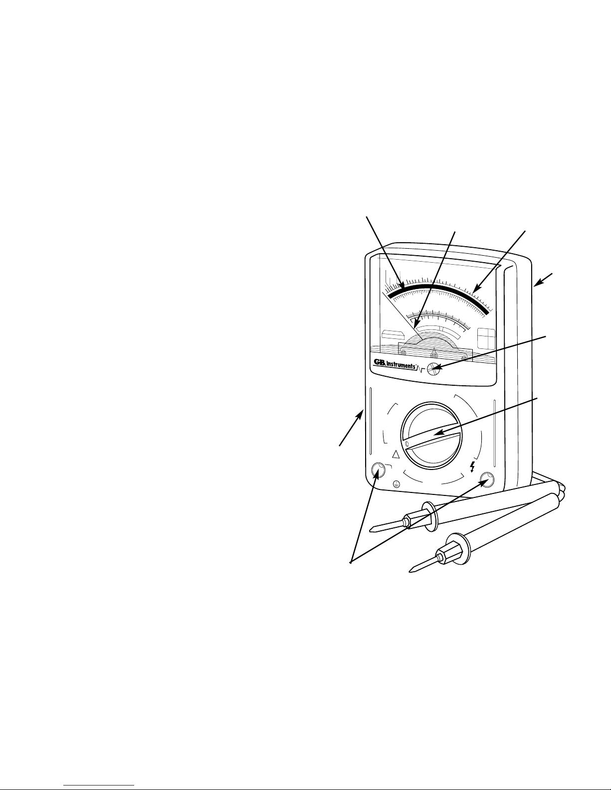
1. Meter Functions
Needle
Analog
Scale
Zero
Adjust
Screw
Zero
Ohms
Adjust
ment
Input Jacks
Function/
Range
Selector
Switch
Contents
1. Meter Functions
2. Specifications
2.1 For Your Safety
3. Operating Suggestions
3.1 Preliminary Adjustments
3.2 Internal Battery Condition
4. DC Voltage Measurement
4.1 Automotive Batteries
4.2 Alternators and Generators
4.3 Household Batteries
5. DC Milliamp Measurement
6. AC Voltage Measurement
6.1 Wall Receptacles
6.2 Appliance Receptacles
6.3 Circuit Breaker Panels
7. Resistance/Continuity Measurement
7.1 Extension Cords
7.2 Appliance Cords
7.3 Fuses
7.4 Switches
7.5 Heating Elements
7.6 Thermostats
8. Decibel Measurement
9. Battery and Fuse Replacement
1
Figure 1
Battery/
Fuse
Cover
Mirror
Page 3

2.1 For Your Safety
1) Use extreme caution when checking electrical circuits.
2)
Do not stand in wet or damp work areas when
working with electricity. Wear rubber-soled boots or shoes.
3) Do not apply more voltage or current than
the set range of the multimeter will allow.
4) Do not touch the metal probes of the test
leads when making a measurement.
5) Replace worn test leads. Do not use test leads with broken
or tattered insulation.
6) Discharge a capacitor before measuring it.
7) Remove the test leads from the circuit being measured as
soon as the test is completed.
8) Do not measure voltage when the
function/range switch is set on the resistance (ohms) or the
current (mA) settings. Never measure current when the meter
is set on the resistance range. Never measure AC voltage
when the meter is set on DC voltage or DCmA. Setting the
meter on the incorrect function may burn out some of the
internal circuitry and may pose a safety hazard.
3. Operating Suggestions
1) Set the function/range switch to the proper position before
making a measurement. When the voltage or current is not
known, it MUST be determined that the capacity of the
selected range will handle the amount of voltage or current
in the circuit (see #3 under For Your Safety). Always start
with the highest range in the function. If the reading falls
within the range of a lower setting, reset the function/range
switch to the appropriate setting for greater accuracy.
2) Avoid placing the meter in areas where vibration, dust or dirt
are present. Do not store the meter in excessively hot,
humid or damp places. This meter is a sensitive measuring
device and should be treated with the same regard as other
electrical and electronic devices.
3) Using the meter in areas with high magnetic fields can result
in inaccurate readings. For greatest accuracy, lay the meter
flat on a non-metallic surface.
4
!
WARNING
!
WARNING
!
WARNING
!
WARNING
2. Specifications
Ranges: 12 measuring ranges
DC Voltage: 10-50-250-500 Volts
AC Voltage: 10-50-250-500 Volts
DC Current (Milliamperes): 0.5-50-250mA
Resistance (Ohms): Rx1K (resistance indicated multiplied by 1000)
1 Megohm max
Decibels: -20dB to +56dB on AC voltage ranges
Accuracy: DC voltage, mA = 4% full scale of range
AC voltage = 5% full scale of range
Resistance = 4° arc of scale length
Sensitivity: 2000 ohms per volt DC and AC
Function/Range Switch: 5 functions
13 positions
12 measuring ranges
Zero Ohms Adjustment Dial: Located on the left side of the housing; adjustment
dial is used to zero the needle indicator on the
ohms scale while shorting the test leads together.
Mechanical Zero
Adjustment Screw: Located directly below the center of the meter
scale; adjust needle indicator to read zero
at the left side of the scale before taking
any measurement.
Mirrored Scale Plate: The mirror on the scale plate is used to line up the
needle with its reflection to improve the reading
accuracy by preventing parallax error.
Recessed Input Jacks: Negative (-) input jack for black test lead, positive
(+) input jack for red test lead.
Important:
Read this operators manual thoroughly before using this
multimeter. This manual is intended to provide basic
information regarding this multimeter and to describe
common test procedures which can be made with this unit.
Many types of appliance, machinery and other electrical
circuit measurements are not addressed in this manual
and should be handled by experienced service technicians.
Use extreme caution when using this
multimeter. Improper use of this meter can result in
severe damage to property, severe personal injury or
death. Follow all instructions and suggestions in this
operators manual as well as normal electrical safety
precautions. Do not use this multimeter if you are
unfamiliar with electrical circuits and proper
test procedures.
3
!
WARNING
Page 4

6
Resistance (Ohms - Ω)
Use the top scale for reading the resistance. If the meter
is set to X1k, multiply the resistance value by 1000Ω.
DC Voltage (V DC)
Use the middle scale directly below the mirror. Match the
dial setting to the highest number on the scale. If the setting
does not match one of the numbers, use a scale that can be
easily multiplied to give the setting (i.e. - for 500V, use the
50V scale and multiply the reading by 10).
AC Voltage (V AC)
Use the same numbers and procedures as used for
the DC voltage setting, but use the scale directly below
the numbers.
DC Milliamps
Use the same scale and procedure as used for the DC
voltage setting.
Decibel Gain (dB) - see pg. 15
Use the scale marked dB to read decibels. Use the chart
at the right of the scale for proper conversion.
3.2 Internal Battery Condition
Before making resistance or continuity tests, check the
condition of the internal battery. First turn the function/range
switch to the ohms Rx1K position. Short the test leads
together and the needle indicator should deflect to the
right side of the scale. Keep the test leads shorted together
while simultaneously turning the zero ohms adjustment
dial until the needle indicator reads zero at the right side
of the ohms (green) scale. If the needle will not zero,
replace the battery with a new 1.5 volt AA size battery
(see Battery Replacement).
4. DC Voltage Measurement
1) Fully seat the test leads in the correct input jacks, (-) black
lead, (+) red lead.
5
4) When the meter is not in use, keep the function/range
switch in the OFF position. This keeps the needle indicator
from deflecting or ”bouncing” excessively.
5) When disconnecting the test leads from the unit, always
grasp the leads where the input jacks meet the meter
housing. Never pull the leads out of the jacks by the
insulated wire or transport the meter using the test leads
as a carrying strap.
6) Never immerse the meter in water or solvents. To clean
the housing use a damp cloth with a minimal amount of
mild soap.
7) If the resistance (ohms) function of the meter is not going to
be used for a week or more, remove the internal battery to
avoid potential leaks that may damage the unit.
3.1 Preliminary Adjustments
Fully seat the test leads in the correct input jacks. If
necessary, using a small flat tip screwdriver, slowly turn
the mechanical zero adjustment screw clockwise or
counterclockwise until the needle indicator is directly over
the three black zeros at the left end of the scale.
Analog Meter:
Reading the Scale
General
The first step in reading the analog scale is to align the
needle with the scale. This is achieved by locating the
mirror on the scale. Line the needle up with its reflection.
When the reflection is hidden by the needle, the needle
is properly aligned.
DC
10
20
50
100
200
500
2K
5K
10K
6
8
1K
Resistance
(Ohms)
Scale
DC Voltage
& Milliamps
Scale
Common Markings
for both the AC &
DC Voltage Scales
AC Voltage Scale
dB Scale for Transistor
Gain Measurement
}
Page 5
8
corrosion resistance, coat the terminals and connectors with
GB #OX-100 anti-oxidant compound (available at your local
hardware store). Replace and tighten the terminal connectors.
Secondly, if the terminals and connectors are making good
contact, touch the test leads to the battery and vehicle
framework as described above (see fig. 2). Note the reading
of the meter. Get an assistant to turn on the headlights while
the test leads are making contact. The needle indicator should
drop a few volts. Should the needle indicator drop 5 volts or
more, the battery should be charged or possibly replaced if
the voltage drop is significant. The circuit may need to be
checked further for problems within the electrical system that
may be draining the battery.
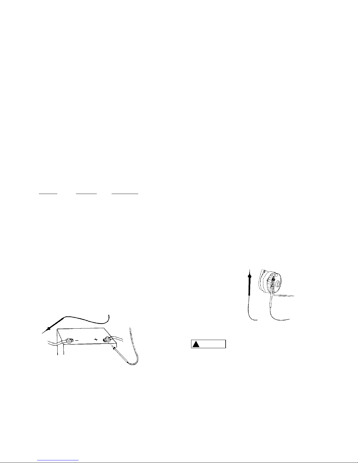
4.2 Alternators and Generators
Set the function/range switch to the 50V DC range. While the
engine is idling at normal operating speed, touch the black (-)
test lead to the metal framework of the vehicle, then touch
the red (+) test lead to the output terminal connector. The
alternator output cable is always the heaviest gauge cable
attached to the alternator (see fig. 3). The needle indicator
should read 12 volts or more. If the needle indicator moves
sporadically, the cable may need to be tightened. If the
engine is idling lower than is specified in the vehicle owners
manual, the voltage reading will be lower. If the output
voltage is significantly low, the alternator may require
service or replacement.
When making automotive measurements,
observe safety precautions. Stay away from the fan blades,
belts and other moving parts of the engine. Keep the
multimeter and its leads away from moving parts.
2) Set the function/range switch to the appropriate DC voltage
range. If the voltage is unknown, use the highest range. If
the voltage applied falls within the range of a lower setting,
reset the function/range switch to the appropriate setting for
greater accuracy.
3) If the polarity of the circuit to be tested is known, touch
the black test lead to the neutral side. If the polarity is
unknown, touch the test leads to opposite sides of the
circuit. If the needle indicator deflects to the left of the scale,
reverse the test leads.
Use the chart below as a guide to reading DC
voltage measurements:
DC V Read and
range following multiply
setting scale reading by:
10 0-10 1
50 0-50 1
250 0-250 1
500 0-50 10
Common DC Voltage Measurements
4.1 Automotive Batteries
Set the function/range switch to 50V DC. First check the
quality of the battery terminal connector by touching the
red (+) test lead to the connector while touching the black (-)
test lead to any bare metal framework of the vehicle. The
meter should read 12 volts or higher on the 0-50 scale with
all of the vehicle accessories turned off. If the needle indicator
moves sporadically, this indicates a bad terminal connection.
Remove the terminal connectors and clean both terminals
and connectors thoroughly. For improved conductivity and
7
Figure 2
Figure 3
!
WARNING
Page 6
Do not apply voltage to the test leads
while the meter is set in the milliamp range. See #8
For Your Safety.
6. AC Voltage Measurement
1) Fully seat the test leads in the correct input jacks.
2) Set the function/range switch to the appropriate AC voltage
range. If the voltage is unknown, use the highest range. If
the voltage applied falls within the range of a lower setting,
reset the function/range switch to the appropriate setting for
greater accuracy.
3) Touch the test leads to the circuit under test. With AC
voltage, the polarity of the test leads is not a factor.
Use the chart below as a guide to reading AC
voltage measurements:
AC V Read and
range following multiply
setting scale reading by:
10 0-10 1
50 0-50 1
250 0-250 1
500 0-50 10
Common AC Voltage Measurements
6.1 Wall Receptacles
If the receptacle is controlled by a switch, make sure the
switch is ON. Set the function/range switch to 250V AC.
Touch the test leads to the “hot” and “neutral” slots of the
receptacle (see fig. 5A). The needle indicator should read
120V AC on the 0-250 scale. To test for proper grounding of
the receptacle, touch one test lead to the “hot” (narrow) side of
the receptacle, and the other test lead to the ground slot. The
meter should read 120V AC as before. To test for proper
grounding of non-polarized receptacles (fig.6), alternately
touch the test leads between the receptacle slots and the wall
plate screw. The meter should indicate 120V AC when one
test lead contacts the “hot” side of the receptacle. If ground
10
4.3 Household Batteries
Set the function/range switch to 10V DC to test household 1.5
volt through 9 volt batteries. Touch the red (+) test lead to the
(+) terminal and the black (-) test lead to the (-) terminal of the
battery. Read the 0-10 scale to determine the condition of
the battery.
5. DC Milliamp Measurement
1) Fully seat the test leads in the correct input jacks.
2) Set the function/range switch to the 250 DCmA setting.
3) Put the test leads in series with the circuit (in line with the
circuit) so that the circuit current passes through the
multimeter in order to make the measurement. If the needle
indicator deflects to the left, reverse the test leads. Read
the measurement on the 0-250 scale.
Common DC Milliamperage Measurements
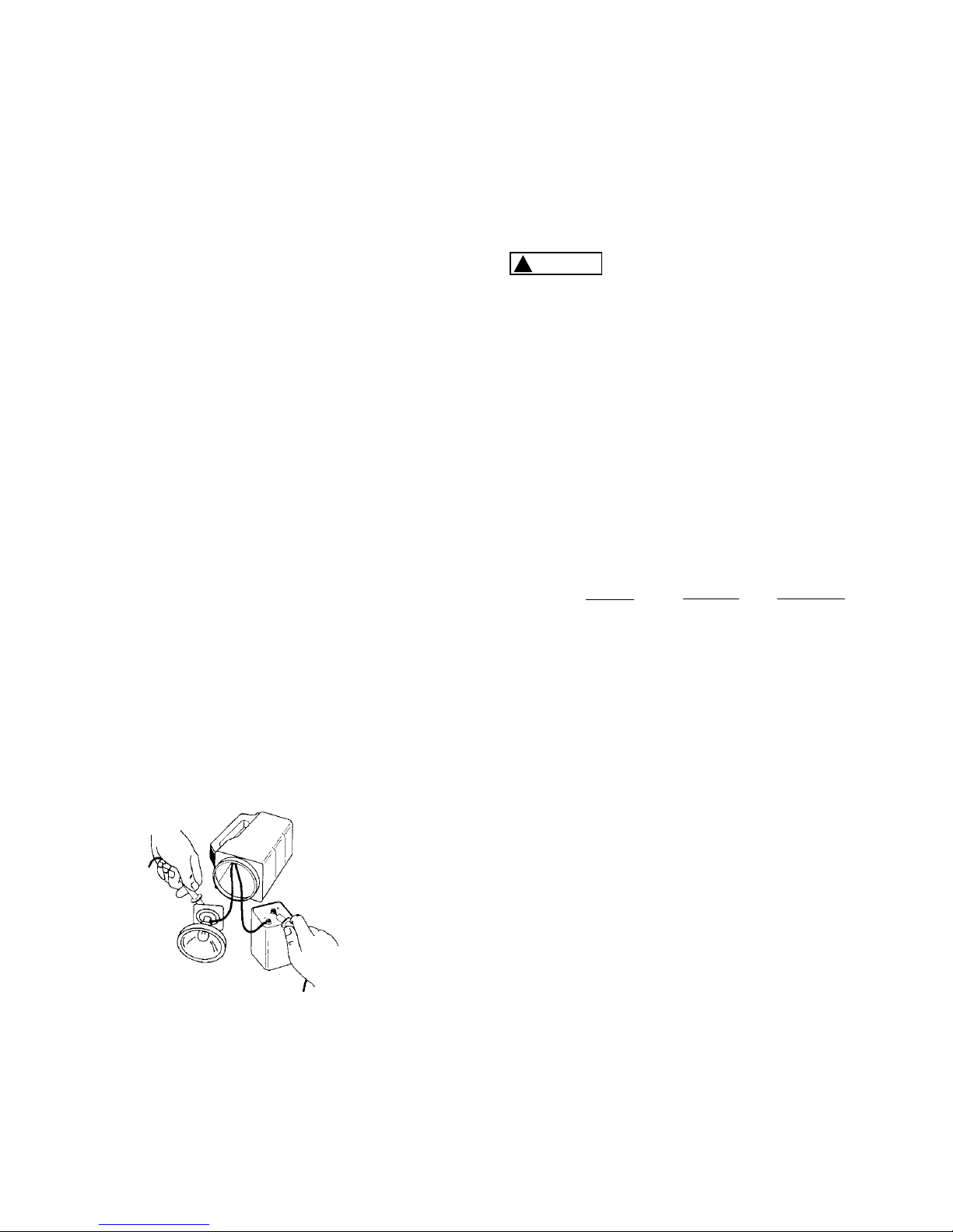
It is important to point out that milliamps can also be
expressed as thousandths of an Ampere; therefore 250
milliamps is 250 thousandths of one Amp. The 250mA
function of your multimeter is commonly used by electronics
repair technicians and hobbyists to troubleshoot various low
voltage circuits. Although not normally used for electrical
troubleshooting around the home, this function can be used to
measure the milliamperage draw of household items such as
flashlights, and other battery operated devices that do not
draw more than 250 mA. In fig. 4 the red (+) test lead is
hooked up to the (+) terminal of the lantern battery while the
black (-) test lead is hooked up to the bulb. The meter will
indicate the milliamperage draw when the flashlight switch is
thrown in the ON position.
Figure 4
!
WARNING
9
Page 7
7. Resistance/Continuity Measurement
For resistance and continuity testing POWER MUST BE OFF:
1) Fully seat the test leads in the input jacks.
2) Set the function/range switch to the Rx1K position
(resistance indicated multiplied by 1000) and short the test
leads together. Using the zero ohms adjustment dial, slowly
turn the dial until the needle indicator reads -0- ohms at the
right end of the ohms scale. If the needle will not zero,
replace the internal battery with a new 1.5 volt AA size
battery (see Battery Replacement).
3) Touch the test leads to the resistance or non-energized
circuit to be measured. Measure the value of the reading on
the green ohms scale and multiply the reading by 1000. If
you’re making basic continuity tests, the needle indicator
should move all the way to the right side of the ohms scale
if continuity exists.
Note: When switching the unit back and forth from ohms
to other functions, always zero the needle indicator before
taking another reading. Failure to zero the needle before
taking resistance/continuity measurements will result in
inaccurate readings.
Common Resistance and Continuity Measurements
Continuity tests are probably the most frequently performed
electrical troubleshooting procedures around the home.
ALWAYS REMEMBER THAT CONTINUITY CHECKS ARE
TO BE MADE WITH THE POWER TO THE CIRCUIT
TURNED OFF. Polarity of the test leads is not a factor in
making continuity checks.
12
contact cannot be made on the wall plate screw, remove the
wall plate and touch the electrical box with the test lead in
the same manner as before. The meter should read 120V
AC with one test lead touching the electrical box and the
other touching the live side of the receptacle. If not, the
receptacle is not properly grounded.
6.2 Appliance Receptacles
Set the function/range switch to 250V AC. Touch the test leads
to the receptacle slots. The meter should read 240V AC between
the two “hot” sides of the receptacle, and 120V AC between the
neutral slot and either of the two “hot” sides (see fig. 7).
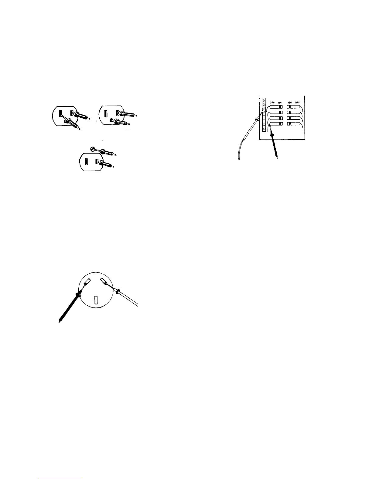
6.3 Circuit Breaker Panel
To test for defective circuit breakers, set the function/range
switch to the 250V AC. Touch one test lead to the neutral
(buss) terminal strip of the breaker panel and the other test
lead to the terminal on the circuit breaker (see fig. 8). The
meter should read 120V AC on the 0-250 scale.
11
Figure 8
Figure 7
Figure 5
Figure 6
5A
5B
Page 8
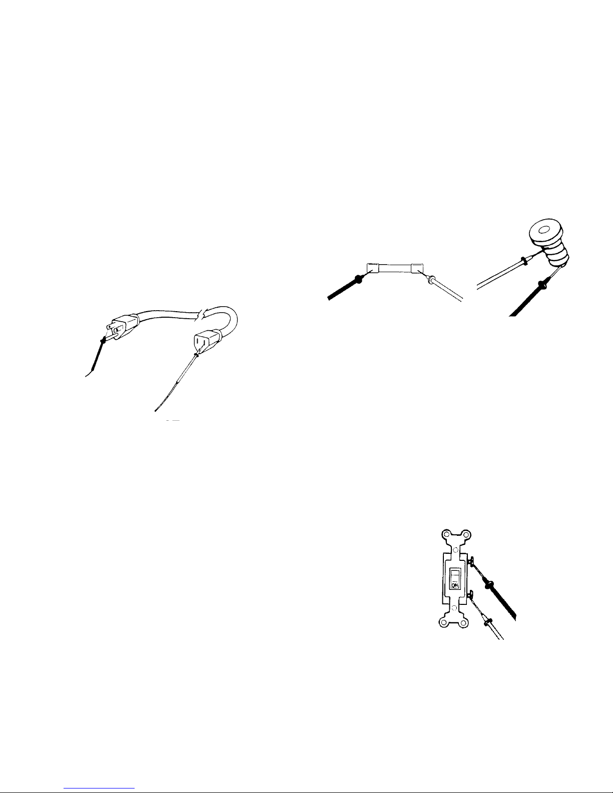
7.3 Fuses
Note: With the power OFF, always remove a fuse from its
socket before testing it. With cartridge fuses, touch the test
leads to each end of the fuse (see fig. 10). If the fuse is good,
the needle indicator will move to -0- ohms. If not, replace the
fuse. On plug-type fuses, touch the the test leads on the
bottom contact and the other on the threaded metal contact
(see fig. 11). On time-delay/tamper-proof fuses, the other
metal contact is at the top of the ceramic threads.
7.4 Switches
Cut off the power source to the switch. If necessary, remove
the switch. Turn the switch to the ON position and touch the
test leads to the switch terminals (see fig. 12). If the switch is
good, the needle indicator will move to -0- ohms. If not,
replace the switch. On other switches such as three-way
light switches or double pole double throw (ON-OFF-ON)
switches, each ON position will need to be tested. Alternate
the test leads between the switch terminals to determine
which two terminals control that ON position.
14
7.1 Extension Cords
Unplug the cord. Set the function/range switch to the Rx1K
position. Touch one of the test leads to one of the metal prong
ends of the cord, and insert the other test lead in either one of
the receptacle slots on the other end of the cord, making sure
the test lead is making good contact with the receptacle (see
fig. 9). If the needle indicator does not move to -0- ohms,
insert the test lead into the other receptacle slot, again making
sure of good contact. If the needle indicator still does not
move the cord has a break and should be replaced.
7.2 Appliance Cords
Unplug the appliance from its power source. Turn its power
switch to the ON position. Touch the test leads to the metal
prong ends of the cord. The meter should indicate a low
resistance value. If not, flex the cord while the leads are still
in contact with the metal prongs. If the needle indicator
moves sporadically while the cord flexes, there may be a
broken conductor in the cord. If the needle indicator does not
move at all, there may be an open circuit in the appliance.
Should it be determined that the cord is not the source of the
problem the appliance may need to be disassembled in
order to pinpoint the problem. Refer to the owners manual of
the appliance. The manufacturer of the appliance may
require that the appliance be serviced only by a qualified
repair technician.
13
Figure 11Figure 10
Figure 12
Figure 9
Page 9

16
9. Battery and Fuse Replacement
1) Remove the screw in the back cover of the meter and
carefully separate the back cover from the front.
2) Note the polarity of the battery when removing it from its
compartment and replace.
3) Use GB catalog number GF-0306 0.5A/250V
replacement fuses.
4) Carefully replace the back cover and tighten the screw.
Do not overtighten, as this may strip the threads in the
meter housing.
7.5 Heating Elements
Household appliances such as coffee makers and water
heaters contain heating elements which may require
troubleshooting. When making continuity checks on heating
elements, disconnect the element(s) from the circuit(s) that
supply it/them. Touch the test leads, one on each end of
the element and observe the needle indicator. The reading
should indicate low ohms. If the needle indicator doesn’t
move, the heating element is broken. If the element(s)
show that continuity exists, test for continuity of the
circuit(s) that feed the element(s).
7.6 Thermostats
Make sure the thermostat control is in the OFF position.
Remove the thermostat cover. Touch the test leads to the
contact points on the thermostat. The needle indicator
should move to read -0- ohms. If not, either one of them
may be loose or broken.
8. Decibel Measurement
The decibel feature of this multimeter is for transistor gain
measurement in electronic circuits and should not be
confused with audio decibels. This function is used
primarily by electronics technicians to measure the power
gain in transistors, and is rarely encountered in home
project applications.
1) Fully seat the test leads in the correct input jacks.
2) Set the function/range switch to any one of the AC voltage
ranges and read the decibel measurement on the bottom
(red) scale of the faceplate. Based on the AC voltage
range you selected, you will need to compute the actual
measurement by using the decibel conversion chart
located at the bottom right of the faceplate.
Important: For absolute decibel measurements, circuit
impedance must be at least 600 ohms. -0- decibels = 1
milliwatt in a 600 ohm impedance (equivalent to 0.775 volts
across 600 ohms).
15
Order Form
Learn more about using multimeters with "How To Use
Your Multitester For Electrical Testing and Troubleshooting".
A 160 page guide to using analog and digital multimeters.
Only available in English. Contains nine chapters of easy to
understand instructions on basic household, automotive
electrical and electronic circuit testing. Packed with
illustrations. Paperback bound. Available wherever
multimeters are sold or:
For customers within the US, send check or money order for
$15.23 per copy ($13.23 plus $2.00 per copy shipping and
handling) to:
Gardner Bender
6101 N. Baker Rd.
Milwaukee, WI 53209
PLEASE PRINT CLEARLY
Name_________________________________________ _________
Address______________________________________ __________
City______________________State__________ Zip_____________
Qty. Ordered___ __________________
Page 10

+
GMT – 12A
P
R
O
T
E
C
T
IO
N
2
K
Ω
/V
D
C
A
C
F
U
S
E
&
D
IO
D
E
200
30
40
60
20
100
1K
0
0
0
AC
DC
50
100
150
200
250
10
20
30
40
2
4
6
8
50
10
AC
dB
DC
dB
B
A
T
10
8
6
5
4
3
2
1
0
Ω
Ω
BAT
G
O
O
D
?
-20
0
+8
+12
+16
+18
+20
+22
∞
R
E
P
L
A
C
E
!
0
d
B
:
1
m
W
6
0
0
Ω
A
C
V
R
A
N
G
E
1
0
5
0
2
5
0
5
0
0
A
D
D
d
B
0
1
4
2
8
3
4
–
OFF
10
50
DC V
250
500
MAX
500V
AC/DC
250
500V
M
A
X
D
C
m
A
50
0.5
O
HM
X1K
10
50
250
500
AC V
1817
Contenido
1. Funciones del probador
2. Especificaciones
2.1 Para su seguridad
3. Sugerencias de operación
3.1 Ajustes preliminares
3.2 Estado de la batería interna
4. Medición de voltaje DC
4.1 Baterías automotrices
4.2 Alternadores y generadores
4.3 Baterías (pilas) domésticas
5. Medición de corriente continua (mA)
6. Medición de voltaje AC
6.1 Receptáculos de pared
6.2 Receptáculos de aparatos
electrodomésticos
6.3 Tablero de cortacircuitos (disyuntores)
7. Medición de resistencia/continuidad
7.1 Cables de extensión
7.2 Cables de aparatos electrodomésticos
7.3 Fusibles
7.4 Interruptores
7.5 Elementos calefactores
7.6 Termostatos
8. Medición de decibeles
9. Reemplazo de la batería y del fusible
Aguja
Escala
analógica
Tornillo
de ajuste
a cero
Ajuste
a cero
ohmios
Enchufes
Selector
de
función/
escala
Figura 1
1. Funciones del probador
Tapa de
batería/
fusible
Espejo
Page 11

20
graves o la muerte. Siga todas las instrucciones y sugerencias de este manual del operador, y observe además las
precauciones normales de seguridad eléctrica. No utilice
este multímetro si no está familiarizado con los circuitos
eléctricos y procedimientos de prueba correctos.
2.1 Para su seguridad
1) Sea sumamente precavido cuando revise
circuitos eléctricos.
2) Aléjese de las áreas mojadas o
húmedas cuando trabaje con electricidad. Use botas o
zapatos con suela de goma.
3) No aplique más voltaje o corriente de
lo permitido por la escala seleccionada en el multímetro.
4) No toque las puntas metálicas de los
conductores de prueba cuando realice mediciones.
5) Reemplace los conductores de prueba desgastados.
No use conductores de prueba con aislamiento roto
o agrietado.
6) Descargue un condensador antes de medirlo.
7) Retire los conductores de prueba del circuito bajo prueba
tan pronto como termine la prueba.
8) No mida el voltaje cuando el selector
de función/escala esté colocado en una de las escalas de
resistencia (ohmios) o de corriente (mA). Nunca mida la
corriente cuando el selector de función/escala esté
colocado en la escala de resistencia (ohmios). Nunca
mida el voltaje de corriente alterna cuando el selector
de función/escala esté colocado en la escala de voltaje
de corriente continua (DC V) o de corriente (mA). Colocar
el probador en la función incorrecta puede fundir algunos
de los circuitos internos, y puede representar un riesgo
de seguridad.
3. Sugerencias de operación
1) Coloque el selector de función/escala en la posición
correcta antes de efectuar una medición. Cuando se
desconozca el voltaje o la corriente, DEBE determinarse
!
PRECAUCION
!
PRECAUCION
!
PRECAUCION
!
PRECAUCION
19
2. Especificaciones
Escalas: 12 escalas de medición
Voltaje DC: 10-50-250-500 voltios
Voltaje AC: 10-50-250-500 voltios
Corriente DC (miliamperios): 0,5-50-250mA
Resistencia (ohmios): Rx1K (resistencia indicada multiplicada
por 1000), 1 Megohm máx.
Decibeles: -20dB a +56dBb en escalas de voltaje AC
Precisión: Voltaje DC, mA = 4% de la escala completa
Voltaje AC = 5% de la escala completa
Resistencia = 4 grados de arco de longitud
de escala
Sensibilidad: 2000 ohmios por voltio de DC y AC
Selector de función/escala: 5 funciones
13 posiciones
12 escalas de medición
Perilla de ajuste a cero ohmios: Localizada en el lado izquierdo de la caja;
la perilla de ajuste se utiliza para poner a cero
la aguja en la escala de ohmios, mientras
se pone en cortocircuito los conductores
de prueba.
Tornillo de ajuste mecánico Localizado directamente abajo del centro de la
a cero: escala del probador; ajuste la aguja a cero en
el lado izquierdo de la escala antes de tomar
cualquier medición.
Placa de escala con acabado El espejo en la placa de escala se utiliza para
de espejo: alinear la aguja con su reflejo para mejorar la
precisión de lectura al evitar el error
de paralaje.
Enchufes empotrados: Enchufe negativo (-) para el conductor de
prueba negro, enchufe positivo (+) para el
conductor de prueba rojo.
Importante:
Lea este manual del operador completamente antes
de utilizar este multímetro. El fin de este manual es
proporcionar información básica relacionada con este
multímetro y describir procedimientos básicos de prueba
que pueden realizarse con este probador. La medición de
muchos tipos de aparatos, maquinaria y otros circuitos
eléctricos no se menciona en este manual y debe solicitarse
la asesoría de técnicos de servicio experimentados.
Sea sumamente precavido cuando use
este multímetro. El uso indebido de este probador puede
provocar daños materiales graves, lesiones personales
!
PRECAUCION
Page 12

22
Generalidades
El primer paso para leer la escala analógica es alinear la
aguja con la escala. Localice el espejo y alinee la aguja con
su reflejo. Cuando el reflejo está tapado por la aguja, ésta
está alineada correctamente.
Resistencia (ohmios - W)
Utilice la escala superior para leer la resistencia. Si el
probador está colocado en “X1K”, multiplique el valor de la
resistencia por 1000.
Voltaje DC (“DC V”)
Utilice la escala de en medio directamente abajo del espejo.
Haga coincidir la posición del selector con el número más
alto de la escala. Si la posición no coincide con uno de los
números, utilice una escala que se pueda multiplicar
fácilmente para dar la posición (por ejemplo - para 500V,
use la escala de 50V y multiplique la lectura por 10).
Voltaje AC (“AC V”)
Utilice los mismos números y procedimientos que los
usados para la posición de voltaje DC, pero use la escala
que se encuentra directamente abajo de los números.
Miliamperios DC
Utilice la misma escala y procedimientos que los usados
para la posición de voltaje DC.
21
que la capacidad de la escala seleccionada acepte la
cantidad de voltaje o corriente del circuito (vea el No. 3
bajo la sección Para su seguridad). Siempre empiece con
la escala más alta en la función. Si la lectura cae dentro
de la escala de una posición inferior, coloque el selector
de función/escala en la posición correcta para obtener
mayor precisión.
2) Evite colocar el probador en áreas donde exista vibración,
polvo o suciedad. No almacene el probador en lugares
excesivamente calientes o húmedos. Este probador es
un dispositivo de medición sensible y debe ser tratado
con el mismo cuidado que otros dispositivos eléctricos
y electrónicos.
3) Utilizar el probador en zonas con campos magnéticos
altos puede dar lecturas incorrectas. Para mayor
precisión, coloque el probador horizontalmente en una
superficie no metálica.
4) Cuando no use el probador, mantenga el selector de
función/escala en posición de apagado (OFF). Esto
protege la aguja contra deflexión o “rebote” excesivo.
5) Cuando desconecte los conductores de prueba del
probador, siempre tómelos desde donde los enchufes se
encuentran con la caja del probador. No tire de los
conductores por el cable aislado para sacarlos de los
enchufes ni lleve el probador utilizando los conductores
de prueba como tiras de transporte.
6) Nunca sumerja el probador en agua ni solventes. Para
limpiar la caja, utilice un paño húmedo con una cantidad
mínima de jabón suave.
7) Si la función de resistencia (ohmios) del probador no se
va a utilizar por una semana o más, retire la batería
interna para evitar fugas potenciales que puedan dañar
la unidad.
3.1 Ajustes preliminares
Asiente completamente los conductores de prueba en los
enchufes correctos. Si es necesario, con un destornillador
plano pequeño, gire lentamente el tornillo de ajuste
mecánico a cero hacia la derecha o hacia la izquierda,
hasta que la aguja esté colocada directamente sobre los
tres ceros negros en el extremo izquierdo de la escala.
DC
10
20
50
100
200
500
2K
5K
10K
6
8
1K
Escala de
resistencia
(ohmios)
Escala de
voltaje DC y
miliamperios
Marcas comunes
para ambas
escalas de voltaje
AC y DC
}
Escala de dB para la medición
de la ganancia de transistores
Escala de
voltaje AC
Page 13

24
10 0-10 1
50 0-50 1
250 0-250 1
500 0-50 10
Mediciones comunes de voltaje DC
4.1 Baterías automotrices
Coloque el selector de función/escala en 50 “DC V”. Primero
revise la calidad del conector del terminal de la batería. Esto
se logra tocando el conductor de prueba rojo (+) con el
conector, mientras toca el conductor de prueba negro (-) con
cualquier estructura metálica del chasis del vehículo. La
lectura del probador debe ser de 12 voltios o superior en la
escala de 0-50, con todos los accesorios del vehículo
apagados. Si la aguja se mueve esporádicamente, esto
indica un desperfecto en la conexión de los terminales. Retire
los conectores de los terminales y limpie ambos terminales y
conectores completamente. Para una mejor conectividad y
resistencia a la corrosión, aplique a los terminales y
conectores una capa de compuesto antioxidante GB No. OX100 (disponible en su ferretería local). Vuelva a instalar y
apriete los conectores. En segundo lugar, si los terminales y
conductores hacen buen contacto, toque la batería y el
chasis del vehículo con los conductores de prueba como se
describió antes (vea la fig. 2).
Observe la lectura del probador. Mientras mantiene contacto
entre la batería y los conductores de prueba, pida a un
asistente que encienda las luces delanteras. La lectura debe
23
Ganancia en decibeles (dB) (Ver la pagina 33)
Utilice la escala marcada dB para leer decibeles.
Utilice la tabla del lado derecho de la escala para la
conversión correcta.
3.2 Estado de la batería interna
Antes de efectuar las pruebas de resistencia o continuidad,
revise el estado de la batería interna. Primero coloque el
selector de función/escala en la posición de ohmios “X1K”.
Ponga en cortocircuito los conductores de prueba uno con
otro, y la aguja debe desviarse al lado derecho de la escala.
Mantenga los conductores de prueba en cortocircuito
mientras gira simultáneamente la perilla de ajuste a cero
ohmios, hasta que la lectura de la aguja sea cero en el lado
derecho de la escala de ohmios (verde). Si la lectura de la
aguja no es cero, reemplace la batería por una nueva
de 1,5 voltios tamaño AA (vea Reemplazo de la batería).
4. Medición de voltaje DC
1) Asiente completamente los conductores de prueba
en los enchufes correctos: (-) conductor negro, (+)
conductor rojo.
2) Coloque el selector de función/escala en la escala de
voltaje DC correcta. Si se desconoce el voltaje, utilice
la escala más alta. Si el voltaje aplicado cae dentro de
la escala de una posición inferior, restablezca el selector
de función/escala a la posición correcta para obtener
mayor precisión.
3) Si se conoce la polaridad del circuito bajo prueba, toque
el conductor de prueba negro con el lado neutro. Si se
desconoce la polaridad, toque los conductores de prueba
con los lados opuestos del circuito. Si la aguja se desvía
a la izquierda de la escala, invierta los conductores
de prueba.
Utilice la tabla siguiente como guía para leer las mediciones
de voltaje DC:
Figura 2
Posición de
la escala
“DC V”
Lea la
siguiente
escala
y multiplique
la lectura por:
Page 14

26
4.3 Baterías (pilas) domésticas
Para probar baterías domésticas de 1,5 a 9 voltios, coloque
el selector de función/escala a 10 “DC V”. Toque el
conductor de prueba rojo (+) con el terminal (+) y el
conductor de prueba negro (-) con el terminal (-) de la
batería. Lea en la escala 0-10 para determinar el estado
de la batería.
5. Medición de corriente continua (mA)
1) Asiente completamente los conductores de prueba en
los enchufes correctos.
2) Coloque el selector de función/escala en la posición de
250 “DC mA”.
3) Coloque los conductores de prueba en serie con el
circuito (en línea con el circuito), de tal forma que la
corriente del circuito pase a través del multímetro para
efectuar la medición. Si la aguja se desvía hacia la
izquierda, invierta los conductores de prueba. Lea la
medición en la escala de 0-250.
Mediciones comunes de
corriente continua (en mA)
Es importante señalar que los miliamperios también pueden
expresarse como milésimas de un amperio; por consiguiente,
250 miliamperios son 250 milésimas de un amperio. La
función 250 mA de su multímetro se utiliza comúnmente por
técnicos de reparaciones de aparatos electrónicos y
aficionados para resolver fallas de varios circuitos de voltaje
bajo. Aunque no lo utilizan normalmente los que reparan
desperfectos eléctricos en el hogar, esta función puede
usarse para medir el consumo de corriente (en miliamperios)
de aparatos domésticos tales como linternas, y otros
aparatos que funcionan con baterías que no consumen más
de 250 mA. En la figura 4, el conductor de prueba rojo (+)
está conectado al terminal (+) de la batería de la linterna,
mientras que el conductor de prueba negro (-) está
conectado al bulbo. El probador indicará el consumo de
corriente (en miliamperios) cuando el interruptor de la linterna
se coloca en posición de encendido (ON).
25
bajar algunos voltios. En caso de que la lectura baje 5
voltios o más, debe cargarse la batería o posiblemente
reemplazarse si la caída del voltaje es significativa.
Además, el circuito debe revisarse más a fondo para ver si
existen problemas dentro del sistema eléctrico que pueden
estar consumiendo el poder de la batería.
4.2 Alternadores y generadores
Coloque el selector de función/escala en la escala de 50
“DC V”. Mientras el motor esté en neutral a una velocidad
normal de funcionamiento, toque el conductor de prueba
negro (-) con el chasis metálico del vehículo, después toque
el conductor de prueba rojo (+) con el conector terminal de
salida. El cable de salida del alternador siempre es el cable
de mayor calibre conectado al alternador (vea la fig. 3). La
lectura de la aguja debe ser de 12 voltios o más. Si la aguja
se mueve esporádicamente, quizá se necesite apretar el
cable. Si el motor está en neutral pero con menos
revoluciones que lo especificado en el manual del vehículo,
la lectura del voltaje será menor. Si el voltaje de salida es
considerablemente más bajo, el alternador puede requerir
servicio o reemplazo.
uando realice mediciones automotrices,
observe las precauciones de seguridad. Aléjese de las
aspas de ventilador, las correas y otras piezas en
movimiento que haya en el motor. Mantenga el probador y
sus conductores de prueba alejados de las partes móviles.
Figura 3
!
PRECAUCION
Page 15

28
Mediciones comunes de voltaje AC
6.1 Receptáculos de pared
Si el receptáculo se controla por un interruptor, asegúrese
de que el interruptor esté en posición de encendido (ON).
Coloque el selector de función/escala en la posición de 250
“AC V”. Toque los conductores de prueba con las ranuras
“energizada” y “neutral” del receptáculo (vea la fig. 5A). La
lectura de la aguja debe ser de 120 voltios AC en la escala
de 0-250. Para probar que el receptáculo esté debidamente
conectado a tierra, toque uno de los conductores de prueba
con el lado “energizado” (angosto) del receptáculo, y el otro
conductor de prueba con la ranura conectada a tierra. La
lectura del probador debe ser de 120 voltios AC, como
antes. Para probar que la conexión a tierra de los
receptáculos no polarizados sea correcta (fig. 6), toque en
forma alterna los conductores de prueba entre las ranuras
del receptáculo y el tornillo de la placa de la pared. El
probador debe indicar 120 voltios AC cuando uno de los
conductores de prueba haga contacto con el lado
“energizado” del receptáculo. Si no puede efectuarse la
conexión a tierra en el tornillo de la placa de la pared, retire
la placa y toque la caja eléctrica con el conductor de prueba
de la misma forma que antes. La lectura del probador debe
ser de 120 voltios AC con un conductor de prueba tocando
la caja eléctrica y el otro tocando el lado vivo del
receptáculo. De lo contrario, el receptáculo no está
debidamente conectado a tierra.
6.2 Receptáculos de aparatos
electrodomésticos
Coloque el selector de función/escala en la posición 250
“AC V”. Toque los conductores de prueba con las ranuras
27
No aplique voltaje a los conductores de
prueba mientras el probador esté colocado en la escala de
miliamperios. Vea el punto No. 8 bajo Para su seguridad.
6. Medición de voltaje AC
1) Asiente completamente los conductores de prueba en los
enchufes correctos.
2) Coloque el selector de función/escala en la escala de
voltaje AC correcta. Si se desconoce el voltaje, utilice
la escala más alta. Si el voltaje aplicado cae dentro de
la escala de una posición inferior, restablezca el selector
de función/escala a la posición correcta para obtener
mayor precisión.
3) Toque los conductores de prueba con el circuito bajo
prueba. Con el voltaje AC, la polaridad de los conductores
de prueba no es importante.
Utilice la tabla siguiente como una guía para la lectura de las
mediciones de voltaje AC:
10 0-10 1
50 0-50 1
250 0-250 1
500 0-50 10
!
PRECAUCION
Figura 4
Posición de
la escala
“AC V”
Lea la
siguiente
escala
y multiplique
la lectura por:
Figura 5
Figura 6
5A
5B
Page 16

30
ohmios. Si la lectura no indica cero, reemplace la batería
por una nueva de 1,5 voltios tamaño AA (vea Reemplazo
de la batería).
3) Toque los conductores de prueba con la resistencia o
el circuito no energizado bajo prueba. Mida el valor de
la lectura en la escala verde de ohmios y multiplique
la lectura por 1000. Si efectúa pruebas básicas de
continuidad, la aguja debe moverse hasta el
extremo del lado derecho de la escala de ohmios si
existe continuidad.
Nota: Cuando cambie el probador de ohmios a otras
funciones o viceversa, siempre coloque la aguja en cero
antes de tomar otra lectura. Si no se coloca la aguja en cero
antes de tomar las mediciones de resistencia/continuidad, la
lectura será imprecisa.
Mediciones comunes de resistencia
y continuidad
Las pruebas de continuidad son los procedimientos de
resolución de fallas que probablemente se efectúan con
más frecuencia en el hogar. RECUERDE SIEMPRE QUE
LAS PRUEBAS DE CONTINUIDAD DEBEN
EFECTUARSE CON LA CORRIENTE ELECTRICA
APAGADA. Cuando se efectúan pruebas de continuidad, la
polaridad de los conductores de prueba no es importante.
7.1 Cables de extensión
Desenchufe el cable. Coloque el selector de función/escala
en la posición de ohmios “X1K”. Toque uno de los
conductores de prueba con uno de los extremos de las
espigas metálicas del cable, e inserte el otro conductor de
prueba en cualquiera de las ranuras del receptáculo en el
otro extremo del cable, asegurándose de que el conductor
de prueba haga buen contacto con el receptáculo (vea la fig.
9). Si la aguja no se mueve a -0- ohmios, introduzca el
conductor de prueba en la otra ranura del receptáculo, de
nuevo asegúrese de que haga buen contacto. Si la aguja
aún no se mueve, el cable está roto y deberá reemplazarse.
29
del receptáculo. La lectura del probador debe ser de 240
voltios AC entre los dos lados “energizados” del receptáculo,
y de 120 voltios AC entre la ranura neutral y cualquiera de
los dos lados “energizados” (vea la fig. 7).
6.3 Tablero de cortacircuitos (disyuntores)
Para probar si existen desperfectos en los cortacircuitos,
coloque el selector de función/escala en la posición 250 “AC
V”. Toque uno de los conductores de prueba con la barra
neutra (bus) de terminales del tablero de cortacircuitos y el
otro conductor de prueba con el terminal del cortacircuitos
(vea la fig. 8). La lectura del probador debe ser de 120
voltios AC en la escala de 0-250.
7. Medición de resistencia/continuidad
Para las pruebas de resistencia y continuidad, LA
CORRIENTE ELECTRICA DEBE ESTAR APAGADA.
1) Asiente completamente los conductores de prueba en los
enchufes correctos.
2) Coloque el selector de función/escala en la posición de
ohmios “X1K” (resistencia indicada multiplicada por 1000)
y ponga en cortocircuito los conductores de prueba uno
con otro. Con la perilla de ajuste a cero ohmios, gire
lentamente la perilla hasta que la lectura de la aguja sea
de -0- ohmios en el extremo derecho de la escala de
Figura 8
Figura 7
Page 17

3231
7.2 Cables de aparatos electrodomésticos
Desenchufe el aparato de la fuente de energía. Coloque el
interruptor de corriente en la posición de encendido (ON).
Toque los conductores de prueba con los extremos de las
espigas metálicas del cable. El probador debe indicar un
valor de resistencia baja. De lo contrario, doble el cable
mientras las puntas aún estén en contacto con las espigas
metálicas. Si la aguja se mueve esporádicamente mientras
se dobla el cable, puede haber un conductor roto en el
cable. Si la aguja no se mueve en absoluto, puede haber un
circuito abierto en el aparato. En caso de determinar que el
cable no es el causante del problema, el aparato quizá
requiera desarmarse para identificar el problema. Consulte
el manual del aparato electrodoméstico. El fabricante del
aparato puede exigir que sólo un técnico calificado le dé
servicio al aparato.
7.3 Fusibles
Nota: Con el suministro eléctrico apagado (OFF), siempre
retire un fusible del zócalo antes de probarlo. Con los
fusibles de cartucho, toque los conductores de prueba con
cada extremo del fusible (vea la fig. 10). Si el fusible está en
buen estado, la aguja se moverá a -0- ohmios. De lo
contrario, reemplace el fusible. En los fusibles de tipo tapón,
toque uno de los conductores de prueba con el contacto
inferior y el otro conductor de prueba con el contacto
metálico roscado (vea la fig. 11). En los fusibles de retardo/a
prueba de manipulaciones no autorizadas, el otro contacto
metálico se encuentra en la parte superior de las roscas
de cerámica.
7.4 Interruptores
Corte el suministro eléctrico al interruptor. Si es necesario,
retire el interruptor. Coloque el interruptor en la posición de
encendido (ON), y toque los conductores de prueba con los
terminales del interruptor (vea la fig. 12). Si el interruptor
está en buen estado, la aguja se moverá a -0- ohmios. De lo
contrario, reemplace el interruptor. En otros interruptores
como los de luz de tres posiciones o los bipolares de doble
vía (ON-OFF-ON), se necesitará probar cada posición de
encendido (ON). Alterne los conductores de prueba entre los
terminales del interruptor, para determinar cuál de los dos
terminales controla dicha posición de encendido (ON).
7.5 Elementos calefactores
Los aparatos electrodomésticos como cafeteras y
calentadores de agua tienen elementos calefactores que
pueden requerir revisiones. Cuando efectúe pruebas de
continuidad en elementos calefactores, desconecte el(los)
elemento(s) del(los) circuito(s) que lo(s) alimenta(n). Toque
los conductores de prueba, uno en cada extremo del
Figura 9
Figura 10
Figura 11
Figura 12
Page 18

elemento y observe la aguja. La lectura debe indicar pocos
ohmios. Si la aguja no se mueve, el elemento calefactor
está roto. Si el(los) elemento(s) muestra(n) que existe
continuidad, pruebe la continuidad del(los) circuito(s) que
alimenta(n) al(los) elemento(s).
7.6 Termostatos
Asegúrese de que el control del termostato esté en la
posición de apagado (OFF). Retire la tapa del termostato.
Toque los conductores de prueba con los puntos de
contacto del termostato. La lectura de la aguja debe
moverse para indicar -0- ohmios. De lo contrario, alguno
de los puntos de contacto puede estar suelto o roto.
8. Medición de decibeles
La función de decibeles de este multímetro es para la
medición de la ganancia del transistor en circuitos
electrónicos, y no debe confundirse con decibeles auditivos.
Esta función la utilizan principalmente los técnicos en
electrónica para medir la ganancia de energía en
transistores, y raramente se utiliza en el hogar.
1) Asiente completamente los conductores de prueba en los
enchufes correctos.
2) Coloque el interruptor de función/escala en cualquiera de
las escalas de voltaje AC y lea la medición de decibeles
en la escala inferior (roja) de la carátula. Según la escala
del voltaje AC que seleccionó, necesitará calcular el valor
real utilizando la tabla de conversión de decibeles
localizada en el lado inferior derecho de la carátula.
Importante: Para obtener las medidas absolutas de
decibeles, la impedancia del circuito debe ser al menos de
600 ohmios. -0- decibeles = 1 milivatio en una impedancia
de 600 ohmios (equivalente a 0.775 voltios, 600 ohmios).
9. Reemplazo de la batería y del fusible
1) Retire el tornillo en la tapa posterior del probador, y
separe cuidadosamente la tapa posterior de la delantera.
2) Observe la polaridad de la batería cuando la retire de su
compartimiento y reemplácela.
Formulario de pedido
Conozca más sobre el uso de los multímetros. El manual
"How to Use Your Multitester for Electrical Testing and
Troubleshooting" (Cómo usar su multímetro para pruebas y
localización de fallas eléctricas) de 160 páginas y 9
capítulos incluye información sobre el uso de multímetros
analógicos y digitales. Disponible solamente en ingles.
Instrucciones fáciles de entender acerca de las pruebas
básicas de circuitos eléctricos y electrónicos en
aplicaciones caseras y automotrices. Incluye numerosas
ilustraciones. Encuadernación económica. Disponible en
todas las tiendas donde se vendan multímetros o:
Para clientes dentro de las Estados Unidos favor envíar un
cheque u orden de pago por US$15,23 por ejemplar
(US$13,23 más US$2,00 por ejemplar para los gastos de
envío) a:
Gardner Bender
6101 N. Baker Rd.
Milwaukee, Wisconsin 53209 USA
SIRVASE ESCRIBIR CON CLARIDAD
Nombre
Dirección
Ciudad Estado
Código postal País
Cantidad pedida
3) Utilice los fusibles de reemplazo GF-0306 (0,5A/250V)
del catálogo de GB.
4) Reemplace cuidadosamente la tapa posterior y apriete el
tornillo. No apriete el tornillo de más, porque esto puede
dañar las roscas de la caja del probador.
3433
Page 19

+
GMT – 12A
P
R
O
T
E
C
T
IO
N
2
K
Ω
/V
D
C
A
C
F
U
S
E
&
D
I
O
D
E
200
30
40
60
20
100
1K
0
0
0
AC
DC
50
100
150
200
250
10
20
30
40
2
4
6
8
50
10
AC
dB
DC
dB
B
A
T
10
8
6
5
4
3
2
1
0
Ω
Ω
BAT
G
O
O
D
?
-20
0
+8
+12
+16
+18
+20
+22
∞
R
E
P
L
A
C
E
!
0
d
B
:
1
m
W
6
0
0
Ω
A
C
V
R
A
N
G
E
1
0
5
0
2
5
0
5
0
0
A
D
D
d
B
0
1
4
2
8
3
4
–
O
FF
10
50
DC V
250
500
MAX
500V
AC/DC
250
500V
M
A
X
D
C
m
A
50
0.5
OHM
X1K
10
50
250
500
AC V
Table des Matières
1. Fonctions du multimètre
2. Caractéristiques
2.1 Sécurité
3. Conseils d’utilisation
3.1 Réglages préliminaires
3.2 Etat de la pile interne
4. Mesure de tension c.c.
4.1 Batteries automobiles
4.2 Alternateurs et dynamos
4.3 Piles d’usage domestique
5. Mesure d’intensité c.c. (mA)
6. Mesures de tension c.a.
6.1 Prises murales
6.2 Prises d’appareils électroménagers
6.3 Panneau de disjoncteurs
7. Mesures de résistance/continuité
7.1 Rallonges
7.2 Cordon des appareils électroménagers
7.3 Fusibles
7.4 Commutateurs
7.5 Eléments chauffants
7.6 Thermostats
8. Mesure des décibels
9. Remplacement de la pile et du fusible
35 36
Miroir
Aiguille
Echelle
analogique
Vis de
réglage
du zéro
Réglage
du zéro
de
gamme
d'ohms
Jacks d'entrée
Sélecteur
fonctions/
gammes
Figure 1
1. Fonctions du multimètre
Couvercle
de pile/
fusible
Page 20

2. Caractéristiques
Gammes: 12 gammes de mesure
Tension c.c.: 10-50-250-500 V
Tension c.a.: 10-50-250-500 V
Intensité c.c. (milliampères): 0,5-50-250 mA
Résistance(ohms) : Rx1K (résistance indiquée multipliée par 1000),
1 Mégohm max
Décibels: -20 dB à +56 dB sur gammes de tension c.a.
Précision: Tension c.c., mA = 4 % du total de l’échelle
de gamme
Tension c.a. = 5 % du total de l’échelle
de gamme
Résistance = arc de 4!! de l’échelle totale
Sensibilité: 2000 ohms par volt c.c. et c.a.
Sélecteur fonctions/gamme : 5 fonctions
13 positions
12 gammes de mesure
Molette de réglage du zéro Situé sur le côté gauche du boîtier, cette molette
de gamme d’ohms: permet de mettre l’aiguille sur le zéro d’une
gamme d’ohms lorsque les deux sondes sont
mises en contact l’une avec l’autre.
Vis de réglage mécanique Située au-dessous de l’échelle, au centre, cette
du zéro: vis permet de mettre l’aiguille sur le zéro de
la gauche de l’échelle avant de prendre
toute mesure.
Miroir d’échelle: Le miroir de l’échelle permet d’aligner l’aiguille
sur sa propre réflexion afin d’obtenir des
mesures plus précises en évitant les erreurs
de parallaxe.
Jacks d’entrée en retrait: Jacks d’entrée négative (-) pour la sonde noire
et d’entrée positive (+) pour la sonde rouge.
Important:
Avant d'utiliser le multimètre, lire attentivement ce manuel. Il
contient les caractéristiques de l'instrument et les contrôles
courants qu'il permet d'effectuer. Le contrôle d'appareils
électroménagers, de machines et autres circuits électriques
dont ne traite pas ce manuel doit être confié à des
techniciens d'entretien expérimentés.
Utiliser ce multimètre avec la plus
grande prudence. Un usage incorrect pourrait résulter
en des dommages matériels importants et des blessures
graves ou mortelles. Suivre toutes les instructions et
recommandations de ce manuel d’utilisation et prendre
toutes les précautions normales concernant l’électricité.
Ne pas utiliser ce multimètre sans être familiarisé
avec les circuits électriques et les méthodes de
test appropriées.
2.1 Sécurité
1) Faire preuve d'une prudence extrême lors de la
vérification des circuits électriques.
2) Eviter tout contact avec de l'eau
ou une surface humide lors du travail sur un circuit
électrique. Porter des bottes ou des chaussures à semelle
de caoutchouc.
3) N'appliquer ni tension ni courant
supérieurs à la limite de la gamme de mesure permise par
le multimètre.
4) Ne pas toucher les sondes d'essai
métalliques pendant une mesure.
5) Remplacer les sondes d'essai usées. Ne pas utiliser de
fils d'essai dont l'isolation est coupée ou déchiquetée.
6) Décharger un condensateur avant de le contrôler.
7) Retirer les sondes d’essai du circuit testé dès que la
mesure est terminée.
8) Ne pas mesurer la tension lorsque
le sélecteur fonctions/gammes est sur une gamme de
résistance (ohms) ou d’intensité (mA). Ne pas mesurer
l'intensité lorsque le sélecteur fonctions/gammes est sur
une gamme de résistance (ohms). Ne pas mesurer une
tension c.a. lorsque le sélecteur fonctions/gammes est sur
une gamme de tension c.c. (DC V) ou intensité (mA). Un
réglage incorrect de l’appareil peut griller certains circuits
internes et être dangereux.
3. Conseils d’utilisation
1) Avant de procéder à toute mesure, régler le sélecteur
fonctions/gammes sur la position voulue. Si la tension ou
l'intensité du courant est inconnue, S'ASSURER que la
gamme choisie a une limite nominale suffisante pour
permettre de mesurer la tension ou l'intensité du circuit
(voir Sécurité n° 3). Toujours commencer avec la gamme
la plus élevée d’une fonction. Si la valeur mesurée
appartient à une gamme inférieure, mettre le sélecteur
fonctions/gammes sur la position permettant une plus
grande précision.
2) Eviter d'exposer le multimètre aux vibrations, à la
!
AVERTISSEMENT
!
AVERTISSEMENT
!
AVERTISSEMENT
!
AVERTISSEMENT
!
AVERTISSEMENT
37 38
Page 21

poussière et à la saleté. Le ranger à l'abri de la chaleur et
de l'humidité excessives. Cet instrument de mesure
délicat doit être traité avec le même soin que les autres
appareils électriques ou électroniques.
3) L’utilisation du multimètre en présence de champs
magnétiques puissants peut fausser les mesures. Pour
un maximum de précision, poser l’appareil à plat sur une
surface non métallique.
4) Lorsque le multimètre n’est pas en usage, laisser le
sélecteur fonctions/gammes sur la position OFF
(arrêt). Ceci empêche l’aiguille d’osciller ou de
“fouetter” excessivement.
5) Pour débrancher les sondes d'essai du multimètre,
toujours les saisir au point de contact avec le boîtier du
multimètre. Ne jamais tirer sur les fils pour les débrancher
des jacks d’entrée et ne jamais transporter le multimètre
en le tenant par les sondes d'essai.
6) Ne jamais immerger le multimètre dans de l’eau ou des
solvants. Nettoyer le boîtier avec un chiffon humide et un
minimum de savon doux.
7) Si la fonction de résistance (ohms) du multimètre ne doit
pas être utilisée pendant une semaine ou plus, retirer la
pile interne pour éviter les risques de fuites qui pourraient
endommager l’appareil.
3.1 Réglages préliminaires
Insérer les connecteurs des fils de sonde à fond dans les
jacks d’entrée appropriés. Si le réglage du zéro est
nécessaire, tourner lentement la vis de réglage mécanique
dans un sens ou dans l’autre, de façon à placer l’aiguille
exactement au-dessus des trois zéros noirs de l’extrémité
gauche de l’échelle.
Multimètre analogique : lecture de l’échelle
Généralités
La première étape d’utilisation d’un multimètre analogique
est d’aligner l’aiguille sur l’échelle de mesure. Localiser le
miroir et aligner l’aiguille sur sa propre réflexion. Lorsque la
réflexion est cachée par l’aiguille, cette dernière est
correctement alignée.
Résistance (Ohms - W)
Utiliser l’échelle du haut pour mesurer la résistance. Si le
multimètre est réglé sur “X1K”, multiplier la valeur indiquée
par 1000.
Tension c.c. (“DC V”)
Utiliser l’échelle du milieu, qui se trouve juste au-dessous
du miroir. Mettre le sélecteur sur la position correspondant
au nombre le plus élevé de l’échelle. Si le réglage ne
correspond à aucun des nombres, utiliser une échelle
pouvant être facilement multipliée (par ex., pour 500 V
utiliser l’échelle 50 V, puis multiplier la mesure par 10).
Tension c.a. (“AC V”)
Utiliser les mêmes nombres et procédures que pour
la tension c.c., mais consulter l’échelle qui se trouve
directement au-dessous des nombres.
Milliampères c.c.
Utiliser la même échelle et les mêmes procédures que pour
la mesure de tension c.c.
DC
10
20
50
100
200
500
2K
5K
10K
6
8
1K
Echelle de
résistance (ohms)
Echelle de
tension c.c.
et de
milliampères
Graduations
communes des
gammes de
tension c.a. et c.c
}
Echelle dB pour
mesure de gain
de transistor
Echelle
de
tension
c.a.
39 40
Page 22

Gain en décibels (dB) (Voir page 50)
Utiliser l’échelle marquée dB pour la mesure des décibels.
Consulter le tableau à la droite de l’échelle pour la
conversion correcte.
3.2 Etat de la pile interne
Avant d’effectuer des contrôles de résistance ou de
continuité, vérifier l’état de la pile interne. Tout d’abord,
mettre le sélecteur fonctions/gammes sur la gamme d’ohms
“X1K”. Toucher l’une des sondes avec l’autre : l’aiguille doit
basculer vers la droite de l’échelle. Garder les sondes en
contact et tourner la molette de réglage du zéro jusqu’à ce
que l’aiguille se trouve sur le zéro du côté droit de l’échelle
des ohms (verte). Si l’aiguille ne peut pas être mise à zéro,
installer une pile AA de 1,5 V neuve (voir Remplacement
de la pile).
4. Mesure de tension c.c.
1) Insérer les connecteurs des fils de sonde à fond dans les
jacks d’entrée appropriés : (-) fil noir, (+) fil rouge.
2) Mettre le sélecteur fonctions/gammes sur la gamme de
tension c.c. voulue. Si la tension est inconnue, utiliser la
gamme la plus élevée. Si la tension appliquée se trouve
dans une gamme inférieure, mettre le sélecteur
fonctions/gammes sur la valeur permettant la plus
grande précision.
3) Si la polarité du circuit à tester est connue, toucher le côté
neutre avec la sonde noire. Si elle est inconnue, mettre
les sondes d’essai en contact avec les côtés opposés du
circuit. Si l’aiguille oscille vers la gauche de l’échelle,
inverser les sondes d’essai.
Utiliser le tableau ci-dessous comme guide pour
l’interprétation des mesures de tension c.c. :
10 0-10 1
50 0-50 1
250 0-250 1
500 0-50 10
Mesures courantes de tension c.c.
4.1 Batteries automobiles
Mettre le sélecteur fonctions/gammes sur 50 “DC V”. Vérifier
d’abord la qualité de la connexion de la borne de la batterie
en la touchant avec la sonde rouge (+) et en mettant la
sonde noire (-) en contact avec une partie de métal nu
quelconque du châssis du véhicule. Le multimètre devrait
indiquer 12 volts ou plus sur l’échelle de 0 à 50, tous les
accessoires du véhicules étant éteints. L’oscillation
intermittente de l’aiguille indique une connexion
défectueuse. Débrancher les fils de la batterie et nettoyer
soigneusement les cosses et les bornes. Pour une
conductivité et une résistance à la corrosion maximum,
enduire les bornes et cosses de composé antioxydant GB n°
OX-100 (en vente chez votre quincaillier). Remettre les
cosses sur les bornes et les serrer. Ensuite, si le contact
entre les cosses et les bornes est bon, mettre les sondes en
contact avec la batterie et le châssis comme décrit ci-dessus
(voir la fig. 2). Noter l’indication du multimètre. Demander à
un aide d’allumer les phares pendant que les sondes sont en
contact. L’aiguille du multimètre devrait descendre de
quelques volts. Si l’aiguille descend de 5 volts ou plus, la
batterie doit être rechargée ou, si la chute de tension est
considérable, remplacée. Il peut s’avérer nécessaire de
tester davantage le circuit en vue de problèmes susceptibles
de causer une décharge de la batterie.
4.2 Alternateurs et dynamos
Mettre le sélecteur fonctions/gammes sur la gamme 50 “DC
V”. Le moteur tournant au ralenti normal, mettre la sonde
41 42
Gamme de
tension c.c.
Lire l’échelle
suivante
et multiplier la
mesure par :
Figure 2
Page 23

noire (-) en contact avec le châssis métallique du véhicule et
la sonde rouge (+) en contact avec le connecteur de borne
de sortie. Le câble de sortie de l’alternateur est toujours les
plus gros câble branché sur l’alternateur (voir la fig. 3).
L’aiguille du multimètre devrait indiquer 12 volts ou plus. Si
elle oscille sporadiquement, il se peut que le branchement
du câble ait besoin d’être resserré. Si le régime de ralenti du
moteur est inférieur à la valeur spécifiée dans le manuel du
véhicule, l’indication de tension sera plus basse. Si la
tension de sortie est excessivement basse, il est possible
que l’alternateur ait besoin d’être réparé ou remplacé.
Lors des mesures du circuit
électrique d’un véhicule, certaines précautions sont
nécessaires : se tenir à l'écart des pales du ventilateur,
des courroies et autres pièces mobiles du moteur. Tenir
le multimètre et ses fils à distance des pièces mobiles.
4.3 Piles d’usage domestique
Pour tester les piles d’usage domestique de 1,5 à 9 volts,
mettre le sélecteur fonctions/gammes sur 10 “DC V”. Mettre
la sonde d'essai rouge (+) en contact avec la borne (+) de la
pile, et la sonde d'essai noire (-) en contact avec la borne (-)
de la pile. Consulter l’échelle de 0 à 10 V pour déterminer
l’état de la pile.
5. Mesure d’intensité c.c. (mA)
1) Insérer les connecteurs des fils de sonde à fond dans les
jacks d’entrée appropriés.
2) Mettre le sélecteur fonctions/gammes sur la position 250
“DC mA”.
3) Brancher les sondes d’essai en série (en ligne) avec le
circuit afin que le courant de celui-ci traverse le multimètre
pour pouvoir effectuer la mesure. Si l’aiguille du
multimètre oscille vers la gauche, inverser les sondes.
Lire la mesure sur l’échelle de 0 à 250.
Mesures courantes d’intensité c.c. (en mA)
Un milliampère est un millième d’ampère, par conséquent,
250 milliampères représentent 250 millièmes d’ampère. La
fonction 250 mA du multimètre est couramment utilisée par
les techniciens en électronique et les bricoleurs pour
contrôler divers circuits à basse tension. Bien qu’elle ne soit
pas normalement utilisée pour le contrôle des circuits
électriques résidentiels, cette fonction permet de mesurer
l’appel de courant (en milliampères) d’articles ménagers tels
que des lampes de poche et autres appareils fonctionnant
sur piles ne consommant pas plus de 250 mA. Dans la figure
4, la sonde rouge (+) est connectée sur la borne (+) de la
pile de la lampe et la sonde noire (-) sur l’ampoule. Le
multimètre indique alors l’appel de courant lorsque
l’interrupteur de la lampe est en position de MARCHE.
Ne pas appliquer de tension sur les
sondes lorsque le multimètre est en gamme de milliampères.
Voir Sécurité n° 8.
43 44
Figure 3
Figure 4
!
AVERTISSEMENT
!
AVERTISSEMENT
Page 24

6. Mesures de tension c.a.
1) Insérer les connecteurs des fils de sonde à fond dans les
jacks d’entrée appropriés.
2) Mettre le sélecteur fonctions/gammes sur la gamme de
tension c.a. appropriée. Si la tension est inconnue, utiliser
la gamme la plus élevée. Si la tension appliquée tombe
dans une gamme inférieure, mettre le sélecteur sur la
position appropriée afin d’obtenir une précision maximum.
3) Mettre les sondes en contact avec le circuit testé. Avec la
tension c.a. la polarité des sondes est sans importance.
Utiliser le tableau ci-dessous comme guide pour
l’interprétation des mesures de tension c.a. :
10 0-10 1
50 0-50 1
250 0-250 1
500 0-50 10
Mesures courantes de tension c.a.
6.1 Prises murales
Si la prise est commandée par un commutateur, s’assurer
que ce dernier est en position MARCHE. Régler le sélecteur
fonctions/gammes sur 250 “AC V”. Mettre les sondes d'essai
en contact avec les fentes “sous tension” et “neutre” de la
prise (voir fig. 5A). L’aiguille doit indiquer 120 V c.a. sur
l’échelle de 0 à 250. Pour s'assurer que la prise est
correctement mise à la terre : mettre une sonde d'essai en
contact avec la fente “sous tension” (étroite) de la prise, et
l'autre en contact avec la fente de terre. Le multimètre doit
indiquer 120 V c.a., comme précédemment. Pour vérifier la
mise à la terre des prises non polarisées (fig. 6) : mettre les
sondes d'essai alternativement en contact entre les fentes
de la prise et la vis de la plaque murale. Le multimètre doit
indiquer 120 V c.a. lorsqu'une sonde est mise en contact
avec la fente “sous tension” de la prise. Si le contact avec la
terre ne peut pas être établi sur la vis de la plaque murale,
déposer la plaque et mettre la sonde d'essai en contact avec
la boîte électrique, comme précédemment. Le multimètre
doit indiquer 120 V c.a. lorsqu'une sonde d'essai est en
contact avec la boîte électrique, et l'autre avec la fente “sous
tension” de la prise. Si ce n’est pas le cas, la prise n'est pas
correctement mise à la terre.
6.2 Prises d’appareils électroménagers
Régler le sélecteur fonctions/gammes sur 250 “AC V”.
Mettre les sondes d'essai en contact avec les fentes de la
prise. Le multimètre doit indiquer 240 V c.a. entre les deux
fentes “sous tension” de la prise, et 120 V c.a. entre la fente
de terre et n'importe laquelle des fentes “sous tension”
(voir fig. 7).
6.3 Panneau de disjoncteurs
Pour contrôler l'état des disjoncteurs, régler le sélecteur
fonctions/gammes sur 250 “AC V”. Mettre une sonde d'essai
en contact avec le neutre (collecteur) de la plaque à bornes
du panneau de disjoncteurs, et l'autre avec la borne du
disjoncteur (voir fig. 8). Le multimètre doit indiquer 120 V c.a.
sur l’échelle de 0 à 250.
45 46
Gamme de
tension c.a.
Lire l’échelle
suivante
et multiplier la
mesure par :
Figure 5
Figure 6
5A
5B
Figure 7
Page 25

7. Mesures de résistance/continuité
Pour les mesures de résistance et de continuité, l’appareil
testé DOIT ETRE HORS TENSION.
1) Insérer les connecteurs des fils de sonde à fond dans les
jacks d’entrée appropriés.
2) Mettre le sélecteur fonctions/gammes sur la gamme
d’ohms “X1K” (résistance indiquée multipliée par 1000) et
mettre les sondes en contact l’une avec l’autre. Tourner
lentement la molette de réglage du zéro jusqu’à ce que
l’aiguille se trouve sur le zéro à l’extrémité droite de la
gamme d’ohms. Si l’aiguille ne peut pas être mise à zéro,
installer une pile AA de 1,5 V neuve (voir Remplacement
de la pile).
3) Mettre les sondes d’essai en contact avec la résistance ou
le circuit hors tension à tester. Relever la valeur mesurée
sur l’échelle d’ohms verte et la multiplier par 1000. Dans
le cas de tests de continuité élémentaires, l’aiguille doit
aller jusqu’à l’extrémité droite de l’échelle d’ohms si la
continuité existe.
Remarque : lors du passage de la gamme d’ohms à une
autre fonction ou vice versa, toujours régler l’aiguille sur le
zéro avant de prendre une autre mesure. Si l’aiguille n’est
pas remise au zéro avant de prendre une mesure de
résistance/continuité, le résultat sera inexact.
Mesures courantes de résistance/continuité
Le contrôle de la continuité de circuits électriques est
probablement la plus courante des opérations de dépannage
domestique. NE JAMAIS OUBLIER QU'UN TEL
CONTROLE NE DOIT ETRE EFFECTUE QU'APRES MISE
HORS TENSION DU CIRCUIT. Pour les contrôles de
continuité, la polarité des sondes d'essai n'entre pas en ligne
de compte.
7.1 Rallonges
Débrancher la rallonge. Mettre le sélecteur
fonctions/gammes sur la gamme d’ohms “X1K”. Mettre une
des sondes d'essai en contact avec l'une des broches de la
rallonge et insérer l'autre dans une des fentes de la prise, à
l'autre bout de la rallonge, en s'assurant que les deux fils
soient bien en contact (voir fig. 9). Si l’aiguille ne se met pas
sur -0- ohm, insérer la sonde dans l’autre fente en veillant à
nouveau à obtenir un bon contact. Si l’aiguille ne bouge
toujours pas, il existe une rupture dans la rallonge et celle-ci
doit être remplacée.
7.2 Cordon des appareils électroménagers
Débrancher l'appareil de la source d'alimentation. Mettre
l'interrupteur en position de MARCHE. Mettre les sondes
d'essai en contact avec les broches du cordon. Le
multimètre doit indiquer une résistance faible. Si ce n’est pas
le cas, courber le cordon alors que les fils sont toujours en
contact avec les broches métalliques. Si l’aiguille oscille
sporadiquement lorsque le cordon est courbé, il se peut que
l’un des conducteurs soit rompu. Si l’aiguille reste
complètement immobile, il peut y avoir un circuit ouvert dans
l'appareil. S’il est établi que le cordon n'est pas en cause,
envisager de démonter l'appareil pour déterminer l'origine du
problème. Consulter le manuel d'utilisation de l'appareil.
Certains fabricants exigent que leurs produits ne soient
entretenus que par un technicien réparateur agréé.
7.3 Fusibles
Remarque : après avoir coupé l'alimentation, toujours retirer
un fusible de sa douille avant de le vérifier. Pour les fusibles
47 48
Figure 8
Figure 9
Page 26

à cartouche, mettre les sondes d'essai en contact avec
chaque extrémité du fusible (voir fig. 10). Si le fusible est en
bon état, l’aiguille doit indiquer -0- ohms. Si ce n’est pas le
cas, remplacer le fusible. Pour les fusibles bouchon, mettre
une sonde d'essai sur le contact inférieur et l'autre, sur le
contact fileté métallique (voir fig. 11). Sur les fusibles
temporisés/inviolables, l'autre contact métallique est à la
partie supérieure de la céramique filetée.
7.4 Commutateurs
Couper l'alimentation du circuit que commande le
commutateur. Au besoin, retirer le commutateur. Le mettre
en position de MARCHE et mettre les sondes d'essai en
contact avec ses bornes (voir fig. 12). Si le commutateur est
en bon état, l’aiguille doit indiquer -0- ohms. Si ce n’est pas
le cas, remplacer le commutateur. Pour les autres modèles,
tels que les commutateurs tripolaires ou bipolaires
bidirectionnels (MARCHE/ARRET/MARCHE), chaque
position MARCHE doit être testée. Inverser les sondes
d'essai sur les bornes pour déterminer quelle paire
commande la position de MARCHE.
7.5 Eléments chauffants
Les appareils électroménagers tels que les cafetières et les
chauffe-eau comportent des éléments chauffants qui doivent
parfois être dépannés. Avant d'en contrôler la continuité,
débrancher leurs éléments chauffants. Mettre chacune des
sondes d'essai en contact avec une des extrémités de
l'élément, et noter l'indication de l’aiguille. Elle doit
correspondre à une résistance faible. Si l’aiguille reste
immobile, l'élément chauffant est brisé. Si la continuité existe
dans les éléments, vérifier la continuité de leurs circuits
d'alimentation.
7.6 Thermostats
S'assurer que la commande du thermostat est sur ARRET.
Retirer le couvercle du thermostat. Placer les sondes d'essai
sur les points de contact du thermostat. L’aiguille doit
indiquer -0- ohms. Si ce n’est pas le cas, l'un des éléments
peut être débranché ou brisé.
8. Mesure des décibels
La fonction de décibels de ce multimètre permet de mesurer
le gain des transistors de circuits électronique, ce qui n’a
rien à voir avec la mesure de niveau acoustique. Cette
fonction est principalement utilisée par les techniciens en
électronique pour mesurer le gain des transistors et elle est
rarement utilisée pour les projets domestiques.
1) Insérer les connecteurs des fils de sonde à fond dans les
jacks d’entrée appropriés.
2) Mettre le sélecteur fonctions/gammes sur l’une
quelconque des gammes de tension c.a. et lire la valeur
en décibels sur l’échelle (rouge) du bas du cadran. Selon
la gamme de tension c.a. choisie, il sera nécessaire de
calculer la valeur réelle en utilisant le tableau de
conversion se trouvant en bas et à droite du cadran.
Important : pour les mesures absolues de décibels,
l’impédance du circuit doit être d’au moins 600 ohms. -0décibels = 1 milliwatt à une impédance de 600 ohms
(équivalente à 0,775 volts sur 600 ohms).
49 50
Figure 11Figure 10
Figure 12
Page 27

9. Remplacement de la pile et du fusible
1) Retirer la vis du couvercle arrière et le séparer avec
précaution du devant du boîtier.
2) Noter la polarité de la pile avant de la retirer de son
logement et de la remplacer.
3) Utiliser des fusibles de rechange GB numéro de catalogue
GF-0306 (0,5A/250V).
4) Remettre le couvercle arrière en place, avec précaution.
Ne pas trop serrer la vis pour ne pas abîmer le filetage du
boîtier du multimètre.
Bon de commande
Pour vous familiariser avec l'emploi des multimètres,
procurez-vous le guide “How To Use Your Multitester For
Electrical Testing and Troubleshooting” (Comment utiliser le
multimètre pour le contrôle et le dépannage d'appareils
électriques). Disponible uniquement en anglais. Ce guide
d'utilisation de multimètres analogiques et numériques de
160 pages abondamment illustrées comporte neuf chapitres
de directives faciles à comprendre sur l'essai des circuits
électriques domestiques, automobiles et électroniques. Ce
livre broché est en vente chez les détaillants de multimètres
ou :
Pour les clients résidents aux États Unis, envoyez un
chèque ou faites un virement bancaire à
15,23 $US par exemplaire (13,23 $US
plus 2 $US de frais de port et de
manutention) à :
Gardner Bender
6101 N. Baker Rd.
Milwaukee, Wisconsin 53209 USA
REMPLIR LISIBLEMENT
Nom
Adresse
Ville Province
Code postal Pays
51 52
Page 28

Gardner
Bender
www.gardnerbender.com
PO Box 3241 • Milwaukee, WI 53201-3241 • 414-352-4160
6615 Ordan Drive • Mississauga, Ontario L5T 1X2 • 905-564-5749
ZX000132 Rev. A
 Loading...