

Page 1
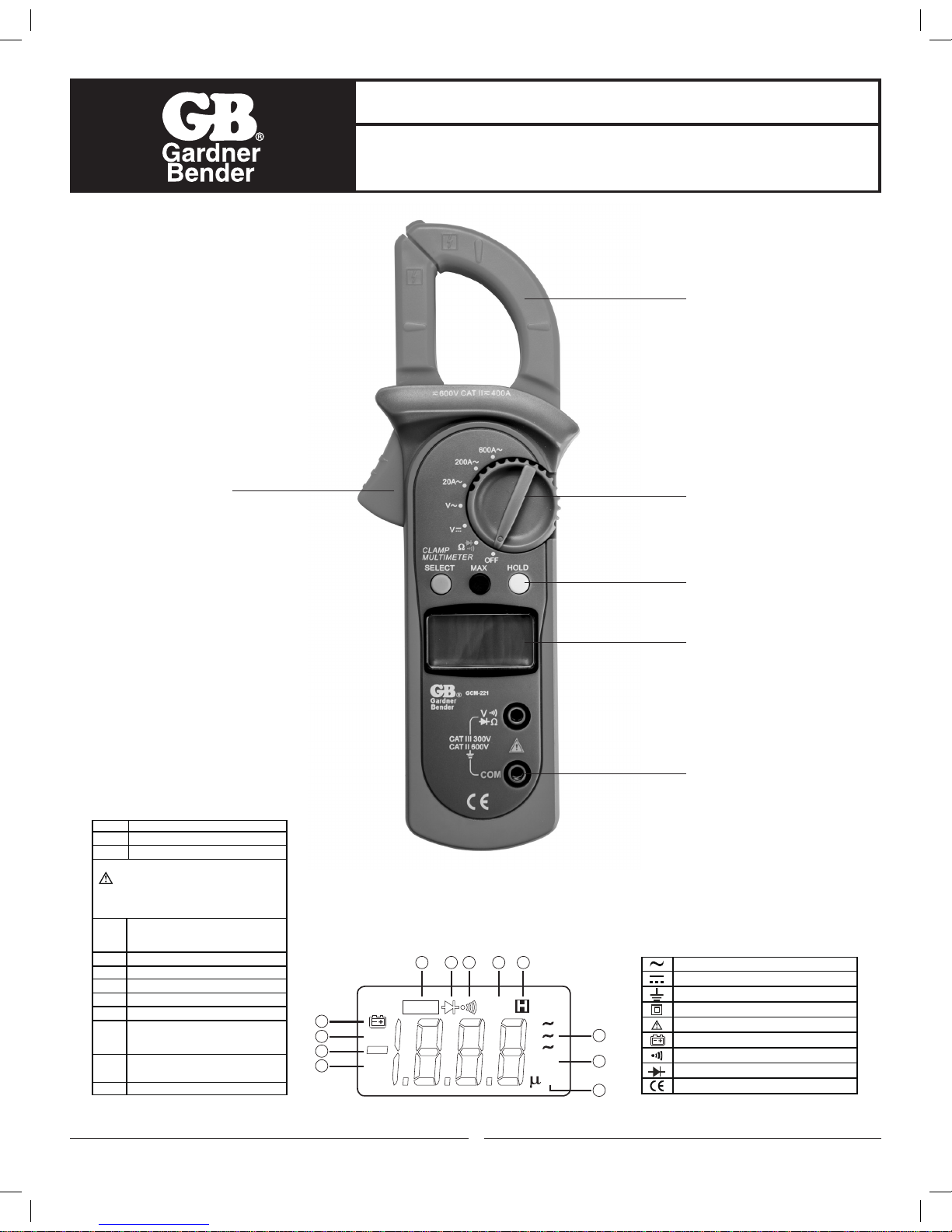
Input Terminals
LCD Display
Functional Buttons
Rotary Switch
Transformer Jaws
Trigger
Figure 1
1
OPERATING INSTRUCTIONS
Digital Clamp Meter
Model GCM-221
Read this owners manual thoroughly before use and save.
Number
Description
1 Indicator for AC voltage or current
2 Indicator for DC voltage
3 The battery is low.
Warning: To avoid false readings, which
could lead to possible electric shock or
personal injury, replace the battery as soon as
the battery indicator appears.
4 The Meter is in the auto range mode in
which the Meter automatically selects
the range with the best resolution.
5 Test of diode
6 The continuity buzzer is on
7 Maximum reading displayed
8 Data hold is active
9 Amperes (amps). The unit of current.
10 Ω: Ohm. The unit of resistance.
kΩ:Kilohm. 1000 ohms
MΩ:Megohm. 1,000,000 ohms
11 V: Volts. The unit of voltage.
mV: Millivolt. 0.001 volts
12 Indicates negative reading
Rotary Functional Buttons
Switch SELECT MAX HOLD
Positions
Ω • N/A •
N/A • •
N/A • •
A 20A N/A • •
A 200A N/A • •
A 600A N/A • •
B. DC Voltage: Auto Ranging
Range Resolution Accuracy
200.0mV 0.1mV ±(0.8%+3)
2.000V 1mV
20.00V 10mV ±(0.8%+1)
200.0V 100mV
600V 1V ±(1%+3)
Remarks:
● Input impedance: 10MΩ
International Electrical Symbols
AC (Alternating Current)
DC (Direct Current)
Grounding
Double Insulated
Warning. Refer to the Operating Manual
Low Battery Indication
Continuity Test
Diode
Conforms to Standards of European Union
Number
Description
1 Indicator for AC voltage or current
2 Indicator for DC voltage
3 The battery is low.
Warning: To avoid false readings, which
could lead to possible electric shock or
personal injury, replace the battery as soon as
the battery indicator appears.
4 The Meter is in the auto range mode in
which the Meter automatically selects
the range with the best resolution.
Rotary Functional Buttons
Switch SELECT MAX HOLD
Positions
Ω • N/A •
N/A • •
N/A • •
A 20A N/A • •
A 200A N/A • •
A 600A N/A • •
I. DISPLAY SYMBOLS
DC
AC
AUTO
TRMS
MAX
˚C˚F
A
A
A
VA
MK
Ω
m
3
9
10
2
12
1
11
4 5 6 7 8
Figure 2
Page 2
DANGER is reserved for conditions and actions that are likely to cause serious or fatal injury.
WARNING is reserved for conditions and actions that can cause serious or fatal injury.
CAUTION is reserved for conditions and actions that can cause injury or instrument damage.
II. SAFETY WARNINGS
• This instruction manual contains warnings and safety rules which must be observed by
the user to ensure safe operation of the instrument and retain it in safe condition.
• Read through and understand the instructions contained in this manual before using the instrument.
• Keep the manual at hand to enable quick reference whenever necessary.
• The instrument is to be used only in its intended applications.
• Understand and follow all the safety instructions contained in the manual.
• It is essential that all safety instructions are adhered to.
• Failure to follow the safety instructions may cause injury, instrument damage
The symbol indicated on the instrument means that the user must refer to the related parts in the
manual for safe operation of the instrument. It is essential to read the instructions wherever the symbol
appears in the manual.
DANGER
• Never make measurement on a circuit in which voltage over 600V exists.
• Do not exceed the CAT rating of the measuring device
• Do not attempt to make measurement in the presence of flammable gases.
The use of the instrument may cause sparking, which can lead to an explosion.
• Transformer jaw tips are designed to not short the circuit during a test. If equipment under test has exposed
conductive parts extra precaution should be taken to minimize the possibility of shorting.
• Never use the instrument if its surface or your hand is wet.
• Do not exceed the maximum allowable input of any measuring range.
• Never open the battery cover during a measurement.
• The instrument is to be used only in its intended applications or conditions.
Use in other than as intended may cause instrument damage or serious personal injury.
WARNING
• Never attempt to make any measurement if any abnormal conditions are noted, such as broken case,
cracked test leads and exposed metal part.
• Do not turn the function selector switch with plugged in test leads connected to the circuit under test.
• Do not install substitute parts or make any modification to the instrument.
Return the instrument to your distributor for repair or recalibration.
• Do not try to replace the batteries if the surface of the instrument is wet.
• Always switch off the instrument before opening the battery compartment cover for battery replacement.
• Set the Function Switch to an appropriate position before starting measurement.
• Firmly insert the test leads.
• Disconnect the test leads from the instrument for current measurement.
• Do not expose the instrument to the direct sun, high temperature and humidity or dewfall.
• Be sure to power off the instrument after use. When the instrument will not be in use for a long period,
place it in storage after removing the batteries.
• Use only a soft cloth dampened with water or neutral detergent for cleaning the meter.
Do not use abrasives, solvents or harsh chemicals. Allow to dry thoroughly before use.
CAUTION
2
Page 3
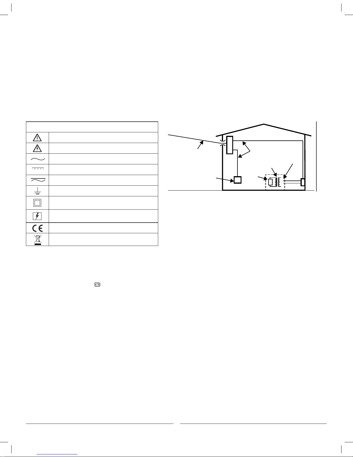
Measurement categories (Over-voltage categories)
To ensure safe operation of measuring instruments, IEC61010 establishes safety standards for various electrical
environments, specified as CAT I through CAT IV, and called measurement categories. Higher-numbered categories
correspond to electrical environments with greater momentary energy, so a measuring instrument designed for CAT III
environments can endure greater momentary energy than one designed for CAT II.
• CAT I: Secondary electrical circuits connected to an AC electrical outlet through a transformer or similar device.
• CAT II: Primary electrical circuits of equipment connected to an AC electrical outlet by a power cord.
• CAT III: Primary electrical circuits of the equipment connected directly to the distribution panel, and feeders
from the distribution panel to outlets.
• CAT IV: The circuit from the service drop to the service entrance, and to the power meter and primary over
current protection device (distribution panel).
Incoming wire
Interior wiring
CAT. III
Transformer
CAT. II
CAT. I
CAT. IV
Socket
Symbols
Caution, risk of danger, refer to the operating manual before use
Caution, risk of electric shock
AC (Alternating Current)
DC (Direct current)
AC/DC Selectable (Alternating Current/Direct Current)
Earth (ground) Terminal
The equipment is protected throughout by
double insulation or reinforced insulation
Application around and removal from hazardous
live conductors is permitted.
Conforms to Standards of European Union
Designates the product as recyclable
electronic waste per WEEE Directive
3
III. GENERAL SPECIFICATIONS
• Display: 3 1/2 digits LCD display, Maximum display 1999
• Auto Polarity Display
• Overloading: Display OL or –OL
• Low Battery Indication: Display
• Measurement Speed: Updates 3 times/second.
• Measuremnet Deviation: When theconductor being
meaured is not placed in a correct position during
AC current measurement, it will cause ±3% reading deviation.
• Drop Test: 1 meter drop test passed
• Max. Jaw Opening: 28mm diameter
• Max. Tested Current Conductor: 26mm diameter.
• Power: 9V battery
• Sleep Mode (can be disabled)
• Dimensions: 76mm x 208mm x 30mm.
• Weight: Approximate 260g (battery included)
• The Meter is suitable for indoor use.
• Altitude: Operating: 2000m
Storage: 10000m
• Safety/ Compliances: IEC 61010 CATII 600V,
CATIII 300V and Double Insulation
• Pollution degree: 2
• Temperature and humidity:
Operating: 0˚C~30˚C (≤75%R.H);
30˚C~40˚C (≤70%R.H);
40˚C~50˚C (≤45%R.H);
Storage: -20˚C~+60˚C (≤75%R.H)
AUTO
T
RMS
MAX
˚C˚F
Page 4
4
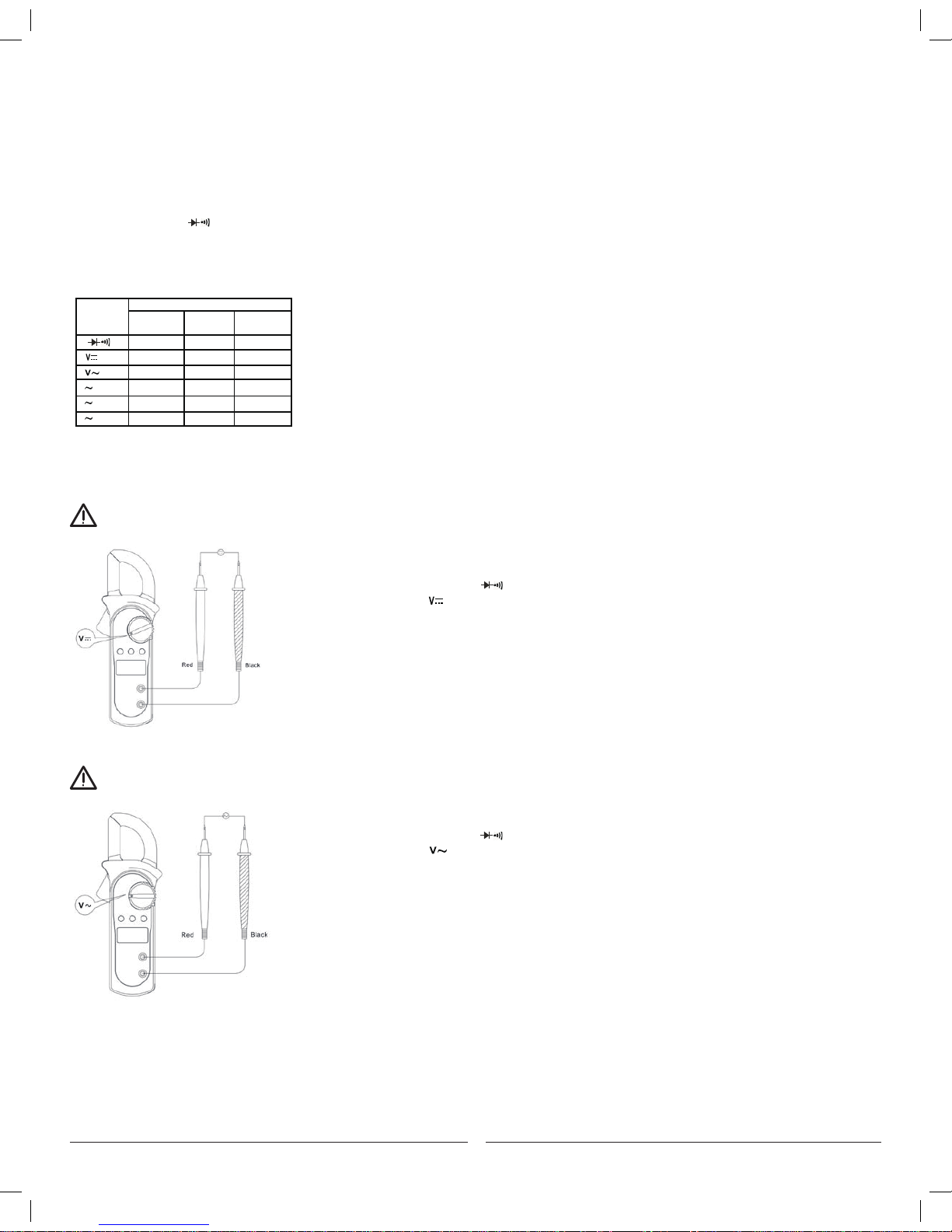
WARNING
V. MEASUREMENT OPERATION
A. Measuring DC Voltage (See Figure 3)
To avoid harm to you or damage to the Meter from electric shock, do not attempt to measure
voltages higher than 600V AC/DC.
To measure DC voltage, connect the Meter as follows:
1. Insert the red test lead into the terminal and the black test lead into the COM terminal.
2. Set the rotary switch to
3. Connect the test leads across with the object being measured.
The measured value shows on the display.
NOTE:
When DC voltage measurement has been
completed, disconnect the connection between
the testing leads and the circuit under test and
remove testing leads from the input terminals.
Figure 3
Figure 4
Figure 5
IV. FUNCTIONAL BUTTONS AND AUTO POWER OFF
1. HOLD: Press the HOLD button to enter & exit the hold mode. Press and hold the HOLD button while turning the Meter on,
the auto power off function will be disabled.
2. AUTO POWER OFF: To preserve the battery life of the Meter, the Meter will automatically go into a "Sleep" mode if you
do not use the device for around 10 minutes. The Meter can be activated by pressing any of the Function Buttons
(refer to #6 Button Functions), then return to the display to view the function.
3. MAX: Press MAX to start recording and updating of maximum values.
4. SELECT: Under functions, the resistance setting will always be the default function.
Press the SELECT button to select the continuity or diode measurement mode.
5. BUZZER: The buzzer will sound every time a function button is pressed. The buzzer will also sound off with 5 "beeps"
approximately 1 minute before the Meters auto power off turns the Meter off.
6. BUTTON FUNCTIONS: The below table describes which function button can be used in regards to the position of the rotary switch.
Rotary Functional Buttons
Switch SELECT MAX HOLD
Positions
Ω • N/A •
N/A • •
N/A • •
A 20A N/A • •
A 200A N/A • •
A 600A N/A • •
*Not every functional button can be used on every rotary switch position.
WARNING
B. Measuring AC Voltage (See Figure 4)
To avoid harm to you or damage to the Meter from eletric shock, do not attempt to measure voltages higher than 600V AC/DC.
To measure AC voltage, connect the Meter as follows:
1. Insert the red test lead into the terminal and the black test lead into the COM terminal.
2. Set the rotary switch to
3. Connect the test leads across with the object being measured.
The measured value shows on the display.
NOTE:
When AC voltage measurement has been
completed, disconnect the connection between
the testing leads and the circuit under test and
remove testing leads from the input terminals.
Figure 4
Figure 5
Page 5
5
WARNING
WARNING
WARNING
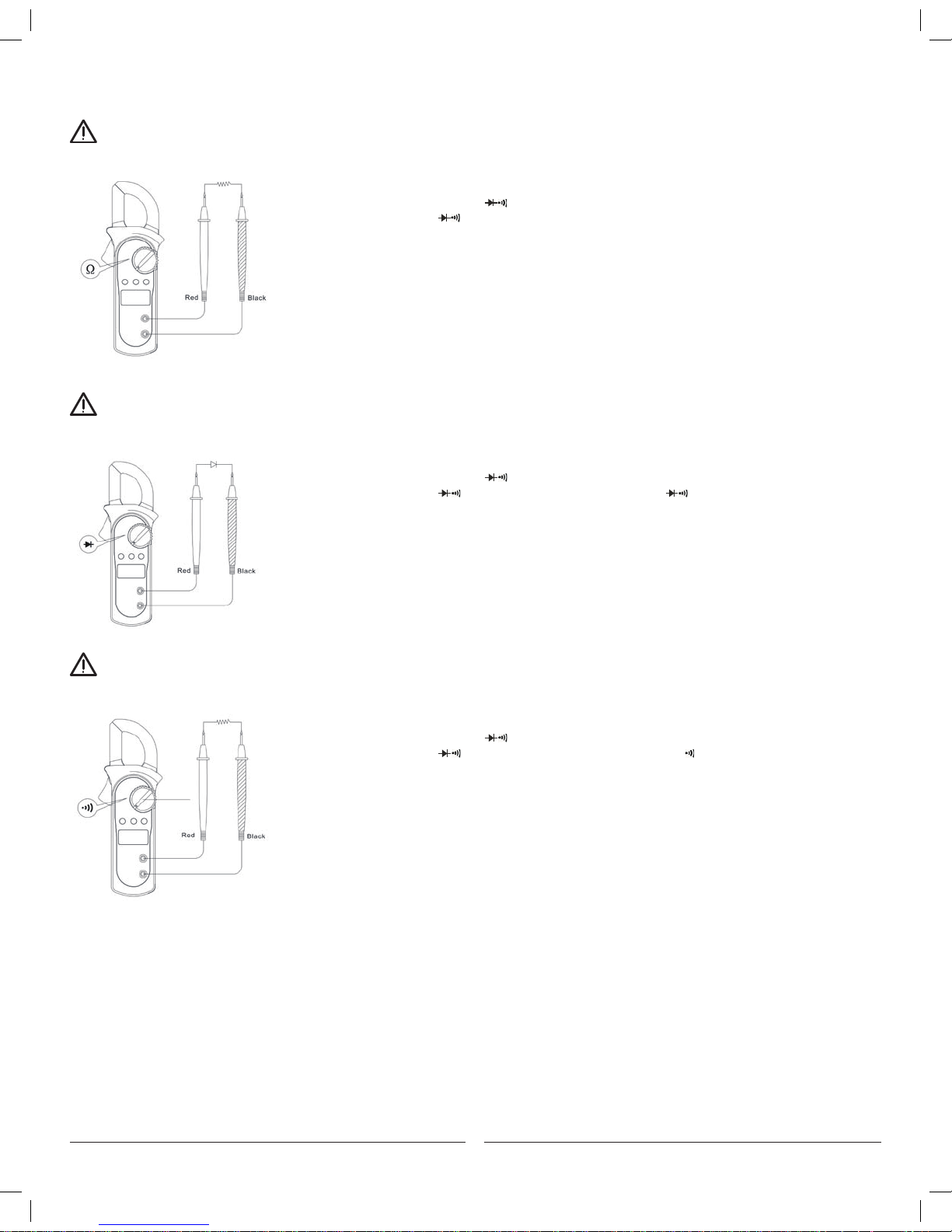
C. Measuring Resistance (See Figure 5)
To avoid damage to the Meter or to the devices under test, disconnect circuit power and discharge all the high-voltage capacitors
before measuring resistance.
To measure resistance, connect the Meter as follows:
1. Insert the red test lead into the v terminal and the black test lead into the COM terminal.
2. Set the rotary switch to ; resistance is the default or press the SELECT button to select
the Ω measurement mode.
3. Connect the test leads across with the object being measured.
The measured value shows on the display.
NOTE:
• Separating the objects being tested from the circuit when measuring
can help obtain a more accurate reading.
• When the resistance measurement has been completed, disconnect the connection
between the testing leads and the circuit under test and remove the testing leads
from the input terminals.
D. Testing Diodes (See Figure 6)
To avoid damage to the Meter or to the devices under test, disconnect circuit power and discharge all the high-voltage
capacitors before testing diodes.
To test the diode out of a circuit, connect the Meter as follows:
1. Insert the red test lead into the v terminal and the black test lead into the COM terminal.
2. Set the rotary switch to and press SELECT button to select measurement mode.
3. For forward voltage drop readings on any semiconductor component, place the red test lead
on the component’s anode and place the black test lead on the component’s cathode.
NOTE:
• Separating the objects being tested from the circuit when
measuring can help obtain a more accurate reading.
• When the diode testing has been completed, disconnect the
connection between the testing leads and the circuit under
test and remove the testing leads from the input terminals.
E. Testing for Continuity (See Figure 7)
To avoid damage to the Meter or to the devices under test, disconnect circuit power and discharge all the high-voltage capacitors
before measuring continuity.
To test for continuity, connect the Meter as follows:
1. Insert the red test lead into the v terminal and the black test lead into the COM terminal.
2. Set the rotary switch to and press the SELECT button to select measurement mode.
3. The buzzer sounds if the resistance of a circuit under test is less than 50Ω.
4. The buzzer may or may not sound if the resistance of a circuit under test is more than 50Ω.
NOTE:
When continuity testing has been completed,
disconnect the connection between the testing
leads and the circuit under test and remove
testing leads from the input terminals.
Figure 5
Figure 3
Figure 2
Figure 4
Figure 5
Figure 6
Figure 7
Figure 3
Figure 4
Figure 5
Figure 7
Figure 7
Page 6

6
WARNING
F. Measuring AC Current (See Figure 8)
To avoid electric shock, never measure current while the test leads are inserted into the input terminals and disconnect test leads and
tested circuit connections. Never attempt an in-circuit current measurement where the open-circuit voltage between the circuit and the
ground is greater than 600V. Use proper function and range for any measurements.
To measure current, do the following:
1. Set the rotary switch to 20A~, 200 A~ or 600 A~
2. Press the trigger to open the transformer jaws.
3. Center the conductor within the transformer jaw, then release the Meter slowly until the
transformer jaw is completely closed, Make sure the conductor to be tested is placed at the
center of the transformer jaw, otherwise it will cause deviation. The Meter can only measure one
conductor at a time, to measure more than one conductor at a time will cause deviation.
NOTE:
When current measurement has been completed,disconnect the
connection between the conductor under test and the jaw, and
remove the conductor away from the transformer jaw of the Meter.
Figure 4
Figure 5
Figure 8
Figure 9
VI. ACCURACY SPECIFICATIONS
Accuracy: ±(a% reading + b digits), guarantee for 1 year.
Operating temperature: 23˚C±5˚C
Relative humidity: ≤75%R.H
Temperature coefficient: 0.1×(specified accuracy) /1˚C
International Electrical Symbols
AC (Alternating Current)
DC (Direct Current)
Grounding
Double Insulated
Warning. Refer to the Operating Manual
Low Battery Indication
Continuity Test
Diode
Conforms to Standards of European Union
Number
Description
1 Indicator for AC voltage or current
2 Indicator for DC voltage
3 The battery is low.
Warning: To avoid false readings, which
could lead to possible electric shock or
personal injury, replace the battery as soon as
the battery indicator appears.
4 The Meter is in the auto range mode in
which the Meter automatically selects
the range with the best resolution.
5 Test of diode
6 The continuity buzzer is on
7 Maximum reading displayed
8 Data hold is active
9 Amperes (amps). The unit of current.
10 Ω: Ohm. The unit of resistance.
kΩ:Kilohm. 1000 ohms
MΩ:Megohm. 1,000,000 ohms
11 V: Volts. The unit of voltage.
mV: Millivolt. 0.001 volts
12 Indicates negative reading
Rotary Functional Buttons
Switch SELECT MAX HOLD
Positions
Ω • N/A •
N/A • •
N/A • •
A 20A N/A • •
A 200A N/A • •
A 600A N/A • •
A. AC Voltage: Auto Ranging
Range
Resolution Accuracy
2.000V
1mV
20.00V
10mV ±(1.2%+5)
200.0V
100mV
600V
1V ±(1.5%+5)
B. DC Voltage: Auto Ranging
Range Resolution Accuracy
200.0mV 0.1mV ±(0.8%+3)
2.000V 1mV
20.00V 10mV ±(0.8%+1)
200.0V 100mV
600V 1V ±(1%+3)
Remarks:
● Input impedance: 10MΩ
● Overload protection: 600V rms
C. Resistance: Auto Ranging
Range Resolution Accuracy
200.0Ω 100mΩ ±(1.2%+2)
2.000kΩ 1Ω
20.00kΩ 10Ω ±(1%+2)
200.0kΩ 100Ω
2.000MΩ 1kΩ ±(1.2%+2)
20.00MΩ 10kΩ ±(1.5%+2)
Remarks:
• Overload protection:600V rms
• Input impedance: 10MΩ // <100pF
• Displays RMS value of sine wave
(mean value response).
• Frequency response: 40Hz~400Hz.
Rotary Functional Buttons
Switch SELECT MAX HOLD
Positions
Ω • N/A •
N/A • •
N/A • •
A 20A N/A • •
A 200A N/A • •
A 600A N/A • •
B. DC Voltage: Auto Ranging
Range
Resolution Accuracy
200.0mV
0.1mV ±(0.8%+3)
2.000V
1mV
20.00V
10mV ±(0.8%+1)
200.0V
100mV
600V
1V ±(1%+3)
Remarks:
• Input impedance: 10MΩ
• Overload protection: 600V rms
Remarks:
• Overload protection: 600Vp
Rotary Functional Buttons
Switch SELECT MAX HOLD
Positions
Ω • N/A •
N/A • •
N/A • •
A 20A N/A • •
A 200A N/A • •
A 600A N/A • •
B. DC Voltage: Auto Ranging
Range Resolution Accuracy
200.0mV 0.1mV ±(0.8%+3)
2.000V 1mV
20.00V 10mV ±(0.8%+1)
200.0V 100mV
600V 1V ±(1%+3)
Remarks:
● Input impedance: 10MΩ
● Overload protection: 600V rms
C. Resistance: Auto Ranging
Range
Resolution Accuracy
200.0Ω 100mΩ
±(1.2%+2)
2.000kΩ
1Ω
20.00kΩ
10Ω ±(1%+2)
200.0kΩ
100Ω
2.000MΩ
1kΩ ±(1.2%+2)
20.00MΩ
10kΩ ±(1.5%+2)
Remarks:
• Overload Protection: 600Vp
• Open circuit voltage approximate 0.45V.
• The buzzer may or may not beeps when
the resistance of a circuit under test is
more than 10Ω.
Rotary Functional Buttons
Switch SELECT MAX HOLD
Positions
Ω • N/A •
N/A • •
N/A • •
A 20A N/A • •
A 200A N/A • •
A 600A N/A • •
B. DC Voltage: Auto Ranging
Range Resolution Accuracy
200.0mV 0.1mV ±(0.8%+3)
2.000V 1mV
20.00V 10mV ±(0.8%+1)
200.0V 100mV
600V 1V ±(1%+3)
Remarks:
● Input impedance: 10MΩ
● Overload protection: 600V rms
C. Resistance: Auto Ranging
Range Resolution Accuracy
200.0Ω 100mΩ ±(1.2%+2)
2.000kΩ 1Ω
20.00kΩ 10Ω ±(1%+2)
200.0kΩ 100Ω
2.000MΩ 1kΩ ±(1.2%+2)
20.00MΩ 10kΩ ±(1.5%+2)
Remark:
● Overload protection: 600Vp
D. Continuity
Range Resolution
Accuracy
Around <10Ω,the
buzzer beeps.
100mΩ
Remarks:
• Overload Protection: 600Vp
• Open circuit voltage approximate 1.48V.
Rotary Functional Buttons
Switch SELECT MAX HOLD
Positions
Ω • N/A •
N/A • •
N/A • •
A 20A N/A • •
A 200A N/A • •
A 600A N/A • •
B. DC Voltage: Auto Ranging
Range Resolution Accuracy
200.0mV 0.1mV ±(0.8%+3)
2.000V 1mV
20.00V 10mV ±(0.8%+1)
200.0V 100mV
600V 1V ±(1%+3)
Remarks:
● Input impedance: 10MΩ
● Overload protection: 600V rms
C. Resistance: Auto Ranging
Range Resolution Accuracy
200.0Ω 100mΩ ±(1.2%+2)
2.000kΩ 1Ω
20.00kΩ 10Ω ±(1%+2)
200.0kΩ 100Ω
2.000MΩ 1kΩ ±(1.2%+2)
20.00MΩ 10kΩ ±(1.5%+2)
Remark:
● Overload protection: 600Vp
D. Continuity
Range Resolution Accuracy
Around <10Ω,the
buzzer beeps.
Remark:
● Overload Protection: 600Vp
● Open circuit voltage approximate 0.45V.
● The buzzer may or may not beeps when the
resistance of a circuit under test is more
than 10Ω.
E. Diode
Range Resolution Accuracy
Display approximate
forward voltage drop
1mV
100mΩ
Remarks:
• Overload protection: 600A rms
• Frequency Response: 50Hz~60Hz
• Displays RMS value of sine wave
(mean value response).
• To adjust reading in accordance
with RMS value.
Rotary Functional Buttons
Switch SELECT MAX HOLD
Positions
Ω • N/A •
N/A • •
N/A • •
A 20A N/A • •
A 200A N/A • •
A 600A N/A • •
B. DC Voltage: Auto Ranging
Range Resolution Accuracy
200.0mV 0.1mV ±(0.8%+3)
2.000V 1mV
20.00V 10mV ±(0.8%+1)
200.0V 100mV
600V 1V ±(1%+3)
Remarks:
● Input impedance: 10MΩ
● Overload protection: 600V rms
C. Resistance: Auto Ranging
Range Resolution Accuracy
200.0Ω 100mΩ ±(1.2%+2)
2.000kΩ 1Ω
20.00kΩ 10Ω ±(1%+2)
200.0kΩ 100Ω
2.000MΩ 1kΩ ±(1.2%+2)
20.00MΩ 10kΩ ±(1.5%+2)
Remark:
● Overload protection: 600Vp
D. Continuity
Range Resolution Accuracy
Around <10Ω,the
buzzer beeps.
Remark:
● Overload Protection: 600Vp
● Open circuit voltage approximate 0.45V.
● The buzzer may or may not beeps when the
resistance of a circuit under test is more
than 10Ω.
E. Diode
Range Resolution Accuracy
Display approximate
forward voltage drop
Remarks:
● Overload Protection: 600Vp
● Open circuit voltage approximate 1.48V.
1mV
100mΩ
F. AC Current: Auto Ranging
Range Resolution Accuracy
20.00A 0.01A ±(2.0%+5)
200.0A 0.1A ±(1.5%+5)
600A 1A ±(2.0%+8)
WARNING
VII. MAINTENANCE
This section provides basic maintenance information including battery replacement instruction.
Do not attempt to repair or service your Meter unless you are qualified to do so and have the relevant calibration,
performance test, and service information.
To avoid electrical shock or damage to the Meter, do not get water inside the case.
A. General Service
• Periodically wipe the case with a damp cloth and mild detergent. Do not use abrasives or solvents.
• Clean the terminals with a cotton swab with mild detergent. Dirt and Moisture in the terminals can affect the readings of the Meter.
• Turn the Meter power off when it is not in use.
• Remove the battery when the unit is not in use for a long time.
• Do not use or store the Meter in a place of humidity, high temperature, explosive, inflammable or strong magnetic field.
Page 7
GAR_TL_061_0616_GCM-221
800.822.9220 • Milwaukee, WI 53209 • gardnerbender.com
GARDNER BENDER LIMITED WARRANTY: Gardner Bender warrants its product against defects in workmanship and materials for 1 year
from date of delivery to user. Chain is not warranted. Warranty does not cover ordinary wear and tear, abuse, misuse, overloading, altered
products or use of improper fluid.
LIMITED: Limited means that GB warrants to the original purchasers of products from GB authorized distributors at the time of shipment such
products shall be free of defects in material and workmanship while the tool is used under normal working conditions. Standard wear and tear,
dulling over time, overloading, misuse, and acts of God are not covered under warranty. This warranty does not cover batteries, fuses,
or test leads.
When a warranty claim arises, the purchaser must contact GB. If the defect comes under the terms of this limited warranty,
GB will arrange, at its sole discretion, one of the following options:
• The product will be repaired at an authorized GB Service Center
• Product will be replaced
The purchaser is solely responsible for determining the suitability of GB for the purchaser’s use or resale, or for incorporating them into articles
or using them in the purchaser’s applications. The distributor is authorized to extend the foregoing limited warranty to its original purchasers in
connection with the sales of GB products, provided that such products shall not have been altered by the distributor. The distributor shall be
fully responsible for any warranties the distributor makes to its purchasers which are broader or more extensive than GB limited warranty.
LIFETIME WARRANTY
Warranty Limitation: The forgoing warranties are exclusive and are in lieu of all other express and implied warranties whatsoever, including but
not limited to implied warranties of merchantability and fitness for a particular purpose. The foregoing warranties do not cover ordinary wear and
tear, abuse, misuse, overloading, alterations, products which have not been installed, operated or maintained in accordance with GB written
instructions. Test leads, fuses, and batteries are not covered under any implied warranty. “Lifetime” of products that are no longer offered by GB
will be either repaired or replaced with an item of GB Instruments choice of similar value. Lifetime is defined as 5 years after GB discontinued
manufacturing the product, but the warranty period shall be at least ten years from date of purchase. Original proof of purchase is required to
establish original ownership of product.
No warranty will be honored unless an invoice or other proof of purchase date is provided to Gardner Bender.
Hand written receipts or invoices will not be honored.
©2016 Product Power, LLC All rights reserved. - See more at: http://www.gardnerbender.com/en/resources/warranty-page#sthash.5Y2dIBQV.dpuf
WARNING
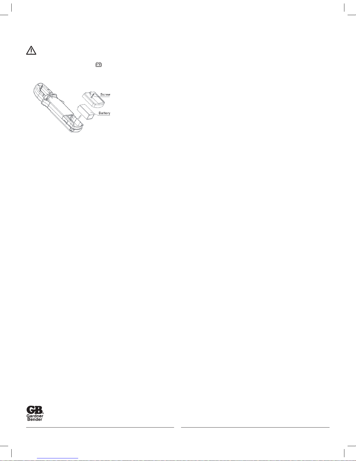
B. Replacing the Battery (See Figure 9)
To avoid false readings, which could lead to possible electric shock or personal injury, replace the battery
as soon as the battery indicator “ ” appears.
Make sure the transformer jaw and the test leads are disconected from the circuit being tested before opening the case bottom.
To replace the battery:
1. Turn the Meter off and remove all the connections
from the input terminals.
2. Turn the Meter’s case top down.
3. Remove the screw from the battery compartment,
and separate the battery compartment from the case bottom.
4. Remove the old battery from the battery compartment and replace it with a new battery.
5. Rejoin the case bottom and the battery compartment,
and reinstall the screw.
Number
Description
1 Indicator for AC voltage or current
2 Indicator for DC voltage
3 The battery is low.
Warning: To avoid false readings, which
could lead to possible electric shock or
personal injury, replace the battery as soon as
Rotary Functional Buttons
Switch SELECT MAX HOLD
Positions
Ω • N/A •
N/A • •
N/A • •
A 20A N/A • •
Figure 5
Figure 9
7
 Loading...