

Page 1
10,000 lb. Cable Puller
Service/Repair Manual
CP10K
SAFETY ISSUES
IMPORTANT – USER SAFETY AND
PROTECTION: In setting up systems to
fit your operations, care must be taken
to select the proper components and
design to insure that all safety measures
have been taken to avoid the risk of
personal injury and property damage
from your application or system.
GARDNER BENDER is not
RESPONSIBLE FOR DAMAGE OR
INJURY CAUSED BY UNSAFE USE,
MAINTENANCE OR THE APPLICATION
OF ITS PRODUCTS. Please contact
Gardner Bender for guidance when
you are in doubt as to the proper safety
precautions to be taken in designing and
setting up your particular application.
Technical Support # 1-800-624-4320.
1.0 Safety Symbol Definitions . . . . . . . . . . . . . . . . . 2
2.0 Warning Labels on Product. . . . . . . . . . . . . . . . 2
3.0 Key Safety Information ...................2
4.0 CP10K Instruction Sheet . . . . . . . . . . . . . . . . . . 2
5.0 Required Tools and Test Equipment . . . . . . . . . 2
6.0 Parts Identification ......................3
US Patent: 8,434,741 B2
7.0 Motor, Guage & Wiring
Troubleshooting Guide ................. 4–5
8.0 Hydraulics ............................. 6
9.0 Boom-B Lock Pin Assembly ..................7
10.0 Motor, Capstan, and Pull Meter ............ 8
11.0 Replacement Parts Guide . . . . . . . . . . . . . . 9–13
1
Page 2
1.0 SAFETY SYMBOL DEFINITIONS
!
!
!
The instruction manual and labels applied to the product provide
information for avoiding injury or death from unsafe practices
related to setting up and operating this machine. It is critical that all
personnel involved with the use of this machine understand these
hazards and unsafe practices. The three levels (Danger, Warning, and
Caution) define the severity of the hazard.
DANGER: Immediate hazards that if not avoided WILL result
in severe injury or death.
WARNING: Serious injury or death COULD occur if proper
attention is not observed.
CAUTION: Injury or property damage MAY occur if proper
attention is not observed.
12. Do not wear jewelry or loose-fitting clothes. Long hair, clothing,
body parts and gloves should be clear of moving parts.
13. Always use all personal safety equipment, including eye
protection and a hard hat.
14. Do not wrap rope around legs, arms or torso of body.
15. Do not plug Power Cord directly into power source. Power
Cord must be plugged into the Footswitch.
4.0 CP10K
INSTRUCTION SHEET
Instruction Sheet IS-164
These Service instructions are intended to be used by a qualified
personal at Authorized Gardner Bender Service Centers. Users
of this product should see the CP10K instruction sheet IS-164 for
installation, operation, and maintenance information.
2.0 WARNING LABELS
ON PRODUCT
The product has safety related labels securely adhered to it in
several locations. They serve to highlight the areas of this machine
that have the potential to cause injury if the operator does not use
caution. The labels include internationally recognized symbols
that are described below.
Read and understand the instruction sheet before
!
setting up or operating this machine.
Body parts are in danger of being crushed by
moving or moveable parts.
Body parts are in danger of being entangled in rope.
Read instruction sheet before operation.
3.0 KEY SAFETY INFORMATION
1. Do not use the cable puller for any other purpose or
application beyond its intended use. It is intended for pulling
wire or cable through fixed conduit, with the conduit adaptor
engaged in the conduit and fastened to the cable puller.
2. Do not operate the cable puller in poorly lit areas.
3. Do not exceed the maximum rated 10,000 lbs. pulling force.
4. Inspect all cable puller components prior to operation.
5. Keep the pull rope away from the operator’s feet. Gather the
tailing rope in an area where the operator or crew cannot
become entangled.
6. Never stand directly under a vertical pull or directly in line with
pull rope under tension.
7. Never use general purpose rope; always use double braided
polyester rope and inspect the rope for damage after each
pull. Do not use damaged rope for pulling cable.
8. Do not allow the rope coils to overlap on the Capstan.
9. Keep bystanders away from operations. Distractions increase
chances of injury.
10. Do not use the cable puller while under the influence of drugs,
alcohol or medication.
11. Do not operate near water or other liquids.
5.0 REQUIRED TOOLS AND
TEST EQUIPMENT
• 3/8"–1-1/4", 1/2" Drive Socket Set
• 1-1/16" Box-end Wrench
• 11/16" Box-end Wrench
• 7/16" Box-end Wrench
• 10" Adjustable Wrench
• E-Ring Install Tool
– A-230
– A-210
– A-200
• SAE Allen Wrench Set
• Pliers
• 3/8" Socket Allen Wrench
• 3/16" Flat Head Screwdriver
• #2 Phillips Screwdriver
• 3/8" Socket Allen Wrench
• Battery Operated Continuity Instrument
DANGER: Make certain that the motor and foot switch are
unplugged prior to performing any repair or service efforts.
FAILURE TO OBSERVE THESE CAUTIONS MAY RESULT IN
DAMAGING MACHINE MOTOR OR SEVERE INJURY.
DANGER: Check for overhead wires prior to unfolding the
boom structure.
FAILURE TO OBSERVE THESE DANGERS WILL RESULT IN
SEVERE INJURY OR DEATH
WARNING: If you do not place your hands as instructed, then
you may crush your hand or fingers. If you do not observe the
machine warning labels, you may crush your hand or fingers.
FAILURE TO OBSERVE THESE WARNINGS COULD
RESULT IN SEVERE INJURY OR DEATH
2
Page 3
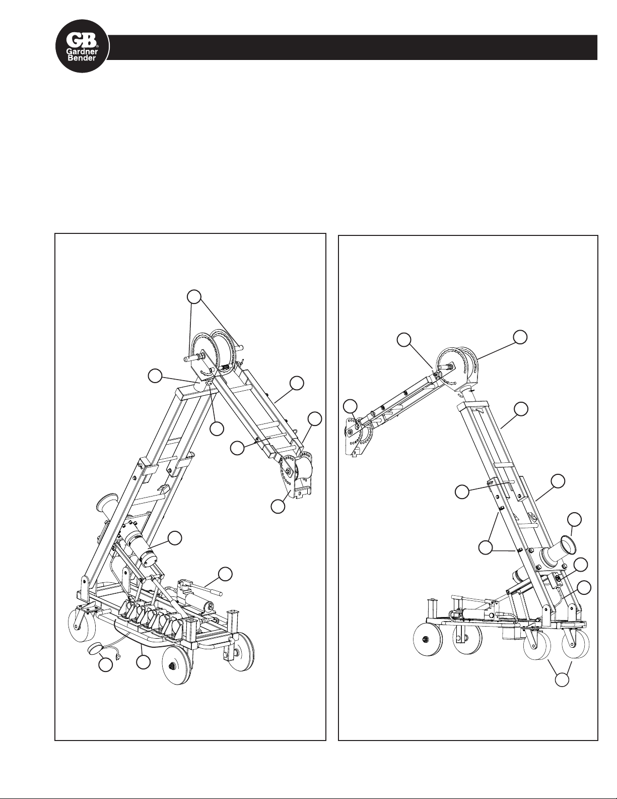
6.0 PARTS IDENTIFICATION
1. Steering Handles
2. Caster Wheels & Brakes
3. Hydraulic Pump
4. Main Boom
5. Boom-A
6. Boom-B
7. Boom-A Lock Pin
8. Pulley-A Housing
9. Boom-B Lock Pin
10. Boom-B Extension
11. Boom-B Extension
Lock Pin
1
12. Pulley-B Housing
13. Pulley-B Housing
Lock Pin
14. Pull Orientation Pivot
15. Pull Orientation Pin
16. Conduit Adaptors
17. Power Cord
18. Footswitch
19. Pull Meter & Switch Box
20. Capstan
21. Motor
22. Pin Clips
9
8
18
16
14
21
15
6
13
10
11
7
12
22
3
5
4
20
19
17
2
3
Page 4

7.0 MOTOR, GUAGE & WIRING TROUBLESHOOTING GUIDE
The CP10K utilizes a DC Permanent Magnet motor. AC power from the wall socket is routed through the Pull Meter & Switch Box
(Item 19) and a Bridge Rectifier in the circuit converts the AC voltage supply to a DC voltage supply to support the motor.
7.1 GENERAL TROUBLESHOOTING
If the capstan does not rotate, there are several possible reasons outlined below.
1. Mechanical Failure
A. Capstan/shaft key is missing
B. Internal gearbox failure
2. Electrical System Failure
A. Source Voltage Failure
B. Foot Switch Failure
C. Pull Meter Switch failure
D. Wiring Circuit Failure
E. Bridge Rectifier Failure
F. Motor Failure
DANGER: All electrical troubleshooting can be successfully
completed with the cable puller disconnected from the voltage supply.
DO NOT CONNECT THE CABLE PULLER TO POWER WHEN
TROUBLESHOOTING ELECTRICAL SYSTEM FAILURES.
FAILURE TO OBSERVE THIS DANGER WARNING WILL RESULT IN
SEVERE INJURY OR DEATH.
7.2 MECHANICAL FAILURE TROUBLESHOOTING
A. If the motor runs when power is applied, but the capstan does not rotate, then confirm that the Capstan/shaft key is intact. See
Section 10.0, Figure 3.
B. If the motor runs when power is applied and the Capstan/shaft key is intact, the Capstan is not rotating due to an internal
gearbox failure. Replace the gear motor or have it serviced.
7.3 ELECTRICAL SYSTEM FAILURE
A. Source Voltage Failure
Check for correct 120 volt AC voltage supply at the wall socket and extension cord if utilized.
B. Foot Switch Failure
Plug the foot switch into a 120 AC volt voltage supply. Do not connect the Foot Switch to the Cable Puller. With the foot switch
depressed to the on position, check the output plug for correct 120 AC voltage supply. Replace the Footswitch if necessary.
C. Pull Meter Switch Failure
Unplug the Cable Puller and Foot Switch from the voltage supply. !! IMPORTANT !!
Remove the 2 screws holding the Pull Meter & Switch Box cover in place.
Carefully pull the cover, including the pull meter away from the box as shown in Figure 1.
Use the probes of a continuity instrument to touch the two switch terminals (WITH NO POWER APPLIED) and check the
operation of the switch. The instrument should indicate continuity with the switch in the on position. The instrument should
indicate no continuity with the switch in the off position. Replace the Switch if necessary.
D. Wiring Circuit Failure
Re-assemble the Pull Meter & Switch Box cover if you removed it in step C.
Make certain that there is no voltage supply to the system.
Remove Pull Meter and Switch Box cover. See Figure 1. This will expose the Bridge Rectifier.
Use a continuity instrument to check for continuity between the Pull Meter & Switch Box plug and the two terminals on the
Bridge Rectifier marked “AC”. Note: the Pull Meter & Switch Box switch has to be in the ON position to allow continuity. The
wiring circuit is okay if each of the plug posts has continuity to one of the Rectifier AC terminals.
4
Page 5

SECTION 7.0 TROUBLESHOOTING – CONTINUED
Figure 1. Pull meter and switch box.
E. Bridge Rectifier Failure
Check your continuity instrument to be identify which probe is positive and which probe is negative. It will depend on how the
batteries were installed in the continuity instrument.
Carefully note the wire terminal locations, then remove all 4 wire terminals from the rectifier.
Touch the positive probe to the unmarked terminal on the rectifier while touching the negative probe to either one of the rectifier
terminals marked “AC”. There should be continuity in either case. Unmarked terminal to AC(1) and Unmarked terminal to AC(2).
Touch the negative probe to the rectifier marked with the “+” sign while touching the positive probe to either one of the rectifier
terminals marked “AC”. There should be continuity in either case. “+” terminal to AC(1) and “+” terminal to AC(2).
If any of the 4 cases does not indicate continuity, then the rectifier has failed. You will not get accurate results for this test
unless you have first identified the positive and negative probes on the continuity instrument, which depends on how the
batteries are installed.
Replace the Bridge Rectifier if necessary. It is important to apply dielectric grease between the rectifier and the mounting
surface.
F. Motor Failure
If steps A through E do not identify a failure, then the motor requires servicing.
SECTION 7.0 TROUBLESHOOTING – CONTINUED
Figure 3. Complete Wiring Schematic.
METER BOX
GROUND SCREW
PULL METER
BLACK
WHITE
BLACK
CRIMP
GREEN
ON/OFF
SWITCH
GREEN
BLACK
RECTIFIER
RED
GREEN
PULLER MOTOR
BLACK
5
Page 6

Figure 4.
3
8.0 HYDRAULICS
8
6
5
9
7
12
13
2
4
10
11
Item Description Qty. Part No. Includes Items
1 Cylinder Kit 1 CP10-114 2, 4, 5, 6
2 Cylinder RC59 1 not sold separately
3 Clevis Eye REB-5 1 not sold separately
4 Clevis Eye Plunger 1 CP10-160
5 Clevis Pin 1 not sold separately
6 E-ring for 1/2” shaft 2 *
7 Hose & Fittings 1 CP10-116 Hose, 3 cable ties
8 Swivel 1 CP10-226
9 Elbow 1 CP10-223
10 Pump P392S Kit 1 CP10-115 Pump & 11, 12, 13
11 Pump Valve Knob DA6301900
12 Screw 1/4-20 x 3/4 SHCS 3 *
13 Washers 1/4 x 0.08 3 *
14 Pump Seal Kit 1 P392ALK
15 Cylinder Seal Kit 1 RC53K1
* Items without part numbers are standard hardware parts available locally.
Hydraulic Service Tips
1. Make certain that the hydraulic pressure is relieved before servicing or unthreading hose.
2. The hose can not be removed unless either the pump or cylinder is removed first.
3. Do not allow the free ends of the hose to come in contact with contaminants while servicing.
4. Check pump fluid level when the pump is horizontal & level and after air is bled from the system.
5. The pump kit and cylinder kit include more detailed instructions.
6. A final step should be to raise the main boom to 30 degrees and check all fittings for leaks.
6
Page 7

Figure 5.
9.0 BOOM-B LOCK PIN ASSEMBLY
1/8" to 3/16"
2
3
5
6
10
4
7
8
11
12
9
GAP
Item Description Qty. Part No. Includes Items
1 Boom-B Lock Pin Kit 1 CP10-144 All items 2–11
2 Index Pin 1 CP10-146 Includes 11 & 12
3 E-ring for 3/4" shaft 1 *
4 Index Joint Washer
25/32 x 1 x 5/32
5 Spring 1 not sold separately
6 Index Joint Bushing 1 not sold separately
7 Index Guide Flange 1 not sold separately
8 Index Joint Lock 1 not sold separately
9 Nut 1/2-13 x 19/64 thick 1 *
10 Screw 1/4-20 x 3/4 SHCS 3 *
11 Handle 1 CP10-237 Includes 12
12 Roll Pin 1/8 x 3/4 1 *
* Items without part numbers are standard hardware parts available locally.
1 *
9.1 LOCK PIN ASSEMBLY SERVICE TIPS
Disassembly
1. Brace Boom-B to remove the weight from the Lock Pin (Item 2)
2. Remove the E-ring (Item 3).
3. Remove the screws (item 10)
9.2 ADJUSTING THE GAP
1. After assembling items 2 through 11, the gap shown above must be adjusted to 1/8"–3/16".
2. Back-off the nut (Item 9) to get it out of the way. Do not remove the nut.
3. Pull on the handle (Item 11) to completely collapse the spring.
4. While pulling on the handle, rotate the Index Lock Joint (Item 8) until the gap is within range (1/8"–3/16").
5. Now allow the Index Lock Joint to engage with the Index Guide Flange slot.
6. Tighten the Nut (Item 9) against the Index Lock Joint (Item 8), while preventing the Index Pin (Item 2) from rotating.
Now the gap will be set.
7
Page 8

Figure 6.
10.0 MOTOR, CAPSTAN, AND PULL METER
3
4
5
24
15
22
Item Description Qty. Part No.
1 Motor & Capstan Kit CP10-129 1, 2, 13
2 Capstan Kit 1 CP10-130 2, 3, 4, 5, 24
3 Bolt 1/2-13 x 1-1/4 SHCS 1 * Same as item 11
4 1/2" High Collar
Lock Washer
5 Washer 1/2" x 1" x 1/8" 1 *
6 Motor Mount Plate Kit 1 CP10-128 7, 8, 9, 10
7 Motor Mount Plate 1 not sold separately
8 Hex Bolt 3/4-10 x 1-3/8 4 *
9 3/4" Spring Washer 4 *
10 Labels 3 not sold separately
11 Bolt 1/2-13 x 1-1/4 SHCS 8 *
12 1/2" High Collar Washer 8 *
1 * Same as Item 12
Includes
Items
17
16
19
Item Description Qty. Part No.
13 Flexible Conduit & Fittings 1 not sold separately
14 Pull Meter & Switch
Box Kit
15 Cord 1 not sold separately
16 Box 1 not sold separately
17 Face Plate & 2 screws 1 not sold separately
18 Pull Meter 1 CP10-185
19 Switch 1 GSW-10
20 Screw #8-32 4 *
21 Label 1 not sold separately
22 Foot Switch 1 CP15
23 Bridge Rectifier 1 CP10-238
24 Key 1/2 x 1/2 x 2 1 not sold separately
18
23
20
13
1 CP10-186 Items 15–21
2
11, 12
1
8
9
7
Includes
Items
* Items without part numbers are standard hardware parts available locally.
Motor, Capstan and Pull Meter Service Tips
1. See Section 7.0 for Troubleshooting these subsystems.
2. Note the orientation and routing of the flexible conduit from the motor to the Pull Meter box.
3. Torque the capstan bolt (Item 3 ) to 119 ft-lbs.
4. Torque the Motor Mount Plate bolts (Item 8) to 250 ft-lbs.
5. Carefully note the orientation of the Bridge Rectifier (Item 23), terminal locations and directions before servicing. See page 5.
8
Page 9

FIGURE 7
11.0 REPLACEMENT PARTS GUIDE
Figure 10
Figure 8
Figure 9
Figure 5
Figure 12
Figure 11
Figure 6
Figure 14
3
Figure 13
6
Figure 4
Item Description Qty. Part No.
Includes
Items
1 Cart Assembly Kit 1 CP10-100 2, 3, 4
2 Cart Weldment 1 not sold separately
3 Push-in Bumper 2 not sold separately
4 Labels 2 not sold separately
5 Wheel Kit 1 CP10-106 6, 7, 8
6 Wheels & Tires 2 not sold separately
2
Item Description Qty. Part No.
7 Lock Nut 3/4-10 x 5/32 2 *
8 Washer 25/32 x 1-5/8 x 5/32 2 not sold separately
9 Castor Kit 1 CP10-107 10, 11, 12
10 Castors 2 not sold separately
11 Hex Bolt 3/8-16 x 7/8 8 *
12 Nut 3/8-16 8 *
* Items without part numbers are standard hardware parts available locally.
10
Includes
Items
9
Page 10

SECTION 11.0 REPLACEMENT PARTS GUIDE – CONTINUED
4
2
8
6
7
FIGURE 8
4
FIGURE 9
10
2
9
8
Item Description Qty. Part No.
1 Pulley-B Assembly Kit 1 CP10-700 Items 2–5
2 Pulley-B Weldment 1 not sold separately
Includes
Items
3 Pivot Pin-B 1 not sold separately
4 Retainer Ring ¾” 2 *
5
3
5 Nylon Washer 13/16 x 1/4 2 not sold separately
6 Pulley-B Roller & Bush-
1 CP10-216
ings
7 Pulley-B Lock Pin Kit 1 CP10-203 8, 9, 10
8 Pulley-B Lock Pin 1 not sold separately
9 D-ring 1 not sold separately
10 Hair Cotter Pin 1 *
6
* Items without part numbers are standard hardware parts
available locally.
Replacementy Labels
(See page 14, Figure 15)
Item Description Qty. Part No.
Includes
Items
1 Boom-B Assembly Kit 1 CP10-600 2, 3
2 Boom-B Weldment 1 not sold separately
3 Labels 4 not sold separately
4 Boom-B Extension 1 CP10-215
* Items without part numbers are standard hardware parts available locally.
Item Description Qty. Part No.
5 Boom-B Extension Lock Pin 1 CP10-138 6, 7, 8
6 Extension Lock Pin 1 not sold separately
7 D-Ring 1 not sold separately
8 Hair Cotter Pin 1 *
10
Includes
Items
Page 11

SECTION 11.0 REPLACEMENT PARTS GUIDE – CONTINUED
3
2
4
5
9
7
6
3
2
6
7
3
FIGURE 10
FIGURE 11
Item Description Qty. Part No.
1 Pulley-A Assembly Kit 1 CP10-500 Items 2–8
2 Pulley-A Weldment 1 not sold separately
3 Handle Grip (Rubber) 2 not sold separately
4 Handle Weldment 2 not sold separately
5 Hex Nylock Nut 3/4-10 2 *
6 Pivot Pin-A 1 not sold separately
7 Nylon Washer 13/16 x 1.4 2 not sold separately
8 Labels 3 not sold separately
9 Pulley-A Roller & Bushings 1 CP10-193
* Items without part numbers are standard hardware parts
available locally.
Includes
Items
Item Description Qty. Part No.
1 Boom-A Assembly Kit 1 CP10-400 2, 3, 4
2 Boom-A Weldment 1 not sold separately
3 Rectangular End Cap 4 not sold separately
4 Labels 2 not sold separately
5 Pull Orientation Pin Kit 1 CP10-189 6, 7
6 Bent pull Hitch Pin 1 not sold separately
7 Hair Cotter Pin 1 *
* Items without part numbers are standard hardware parts available locally.
Includes
Items
11
Page 12

SECTION 11.0 REPLACEMENT PARTS GUIDE – CONTINUED
11
10
9
7
6
2
5
3
4
FIGURE 12
19
Item Description Qty. Part No.
1 Main Boom Assembly Kit 1 CP10-200 Items 2–9
20
2 Main Boom Weldment 1 not sold separately
3 Lock Pin Storage Clip 2 *
4 Screw 6-32 x 1/4
2 *
Sheet Metal
17
16
4
5
3
6
15
5 #6 Washer 2 *
6 Rubber Pads 2 not sold separately
7 Rectangular End Caps 4 not sold separately
8 Labels 10 not sold separately
9 Nameplate 1 not sold separately
10 Main Boom Pivot Pins 1 CP10-122 11, 12, 13
2
11 Clevis Pin 2 not sold separately
12 Retainer Ring 1/2" 4 *
13 Nylon Washer 1/2" 4 *
14 Boom-A Pivot Pins 1 CP10-124 15, 16, 17
15 Boom-A Pivot Pin 2 not sold separately
16 Nylon Washer 3/4" 2 *
13
11
7
12
17 Retainer Ring 3/4" 4 *
18 Boom-A Lock Pin Kit 1 CP10-127 19, 20
19 Lock Pin & D-Ring 1 not sold separately
20 Hair Cotter Pin 1 *
* Items without part numbers are standard hardware parts
available locally.
Includes
Items
FIGURE 13
Item Description Qty. Part No.
1 Lifting Linkage Kit 1 CP10-101 Items 2–7
2 Tubular Link 2 not sold separately
3 Link 2 not sold separately
4 Clevis Pin 1/2 x 1-1/4 2 not sold separately
5 Clevis Pin 1/2 x 2 2 not sold separately
6 Retainer Ring 1/2" 8 *
12
Includes
Items
Item Description Qty. Part No.
Includes
Items
7 Washer 1/2" 12 *
8 Cylinder Plunger Clevis Pin 1 CP10-103 9, 10, 11
9 Clevis Pin 5/8 x 8 1 not sold separately
10 Sleeve 1 not sold separately
11 Retainer Ring 5/8" 2 *
* Items without part numbers are standard hardware parts
available locally.
Page 13

SECTION 11.0 REPLACEMENT PARTS GUIDE – CONTINUED
FIGURE 14
5
4
3
Item Description Qty. Part No.
1 4" Conduit Adaptor 1 CP10-188
2 3-1/2" Inch Conduit
1 CP10-217
Includes
Items
Adaptor
2
3 3" Conduit Adaptor 1 CP10-218
4 2-1/2" Conduit Adaptor 1 CP10-219
1
5 2" Conduit Adaptor 1 CP10-220
6 Hex Bolt 5/8-11 x 1-1/4" 1 *
Each conduit adaptor includes one hex bolt item 6.
* Items without part numbers are standard hardware parts
REPLACEMENT LABELS AND LITERATURE
Item Description Qty.
IS-164 Instruction Sheet 1
TL_001 Service/Repair Manual 1
ZCP00157 Pallet CP10K 1
ZZC401 Label, Keep Hands Clear (2.5 x 1.5) 6
ZZC402 Label, Do Not Touch Rope While Motor Is Running (2 x 2.5) 3
ZZC403 Label, Keep Hands Clear (5.25 x 2.5) 4
ZZC404 Label, Keep Hands Clear When Collapsing (6 x 3) 2
ZZC405 Label, GB Logo, Read, and Warning Symbols (2.5 x 7.5) 1
ZZC406 Label, Keep Hands Clear (4.5 x 1.125) 2
ZZC407 Label, Caution: Must Use For Side Pulls (3 x 1.5) 2
ZZC408 Label, Arrow to show Direction of Rope (6 x 1.5) 1
ZZC409 Label, Arrow for Setup (1 x 2.5) 2
ZZC410 Label, On/Off (1.25 x .5) 1
ZZC411 Label, Upward Pull/Downward Pull (11.25 x .5) 1
ZZC412 Label, Gardner Bender Label (17 x 2) 2
ZZC413 Label, Ultra Brutus, 10,000 lb Cable Puller (13 x 2) 2
ZZC0040 Label, Master, Wrap Around, Red (8 x 1.75) 1
Contact Technical Service at 1.800.624.4320.
13
 Loading...