

Page 1
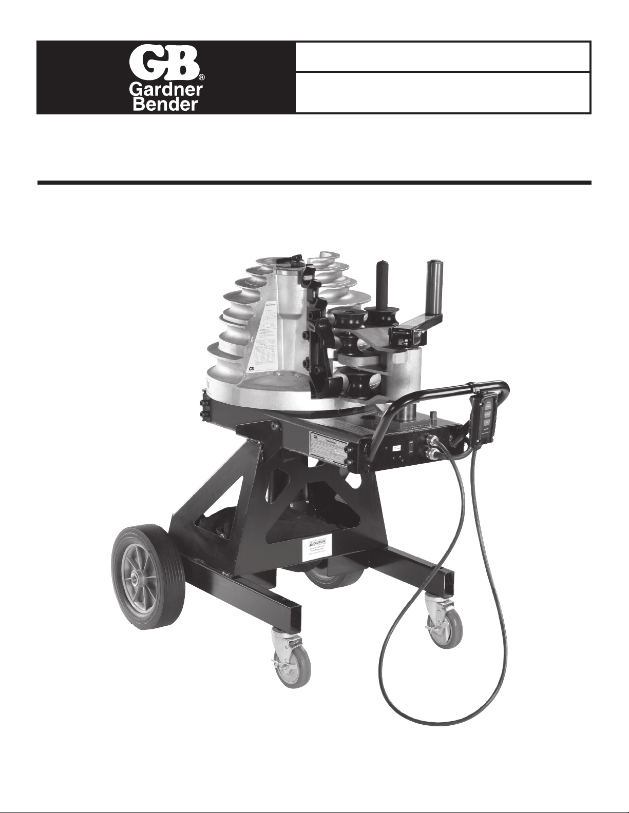
Repair Parts
Effective for models with serial numbers beginning with “N”.
IMPORTANT: RECEIVING INSTRUCTIONS
Visually inspect all components for shipping damage.
If you find damage, notify the carrier at once.
B2000-8 Cyclone
Shipping damage is NOT covered by warranty. The carrier is
responsible for all repair or replacement costs resulting from
damage in shipment.
®
Bender
GAR_TL_024
Page 2
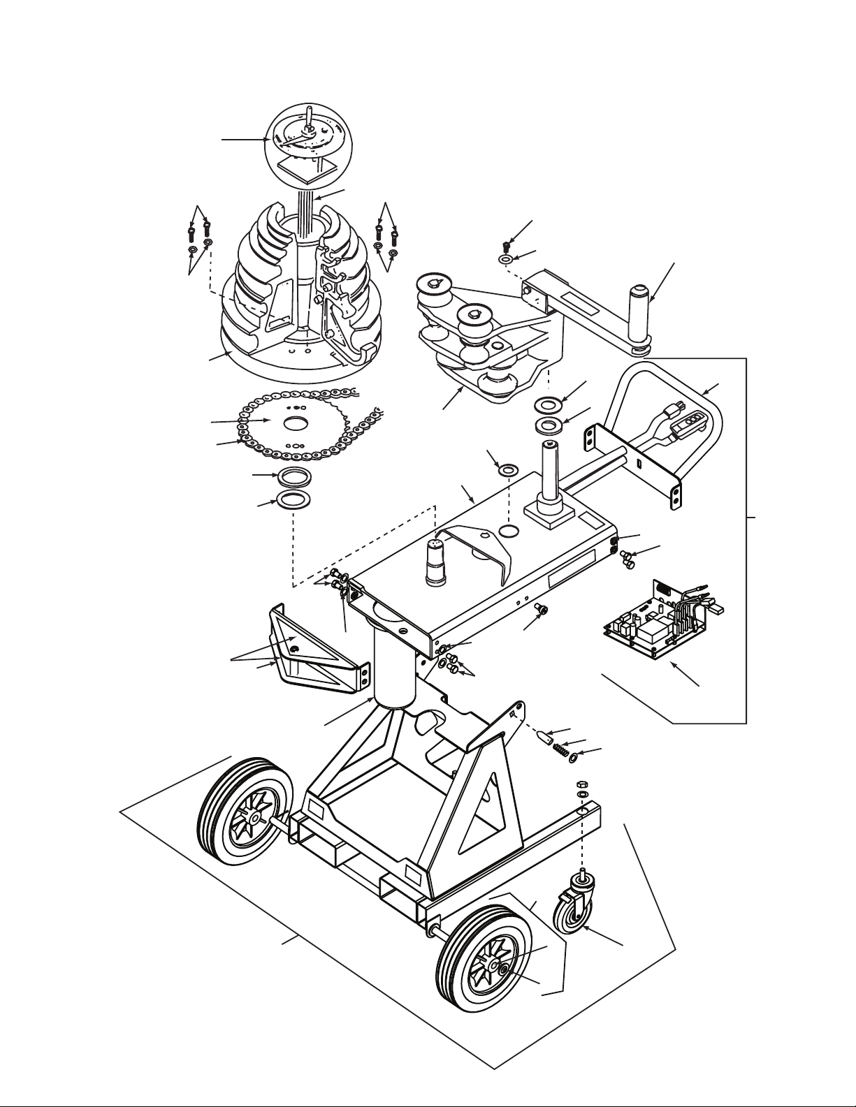
Figure 1
Figure 1
B2000 Bender Assembly
B2000 Bender Assembly
9
2
3
9
23
10
24
10
1
21
22
7
8
5
6
34
35
37
26
20
36
4
35
17
34
35
12
38
27
(See Fig. 7)
34
25
18
21
19
14
15
16
13
SEE INSERT A Page 3
& Fig. 6, (page 8)
11
2
Page 3
INSERT A
28
31
29
30
30
33
32
31
B2000 Bender Assembly
Item # Part # # Req’d Description
1 Figure 2, pg. 4 1 Shoe Sub Assm
2 Figure 3, pg. 5 1 Limit Switch Assm
3 CL712647SR 1 Cable, Limit and Switch
4 SHM115 1 Sprocket Housing
5 CL157108 1 Washer, Shoe
6 CL221108 1 Washer, Thrust
7 CL170228 1 Shoe Sprocket
8 CL333066 1 Chain
9 Common Repl. 4
Part Hex Cap Screw
10 Common Repl. 4
Part
11 LA205 1 Leg Assembly (incl. 13, 19 & 21)
12 CK994900 1 Upper Roller and Handle (Figure 5)
13 CB208 2 Casters Assm (Hardware incl.)
14 CL185061 1 Locking Pin
15 CL183110 1 Spring
16 F57044 1 Ring
17 M00084 2 Screw, Shoulder
18 WB207 2 Wheel Assm (incl. 19 & 21)
19 Common Repl. 2
Part
3
⁄8"-24 x 2-1⁄2 Grade 5 Zinc Plated
3
⁄4" plu SAE Flat Washer
3
⁄32" x 1-1⁄4" Zinc plated cotter pin
B2000 Bender Assembly, cont.
Item # Part # # Req’d Description
20 CU295900K 1 Roller Housing Assm (Figure 4)
21 CK696108 1 Washer
22 CL229248 4 Shim
23 Common Repl. 1
Part Cap Screw Zinc plated
24 Common Repl. 1
Part
25 EC2006 1 Relay Control Assm (Figure 9)
26 LP204 1 End Plate (incl. 34 & 35)
27 HC12 1 Handle & Ctrl Ckt Assm (Figure 7)
28 call tech support 1 Wire Assembly (See Above)
29 call tech support 1 Wire Assembly (See Above)
30 E1001104 2 Push-on Connector (See Above)
31 E1001021 2 Ring-Tongue Connector (See Above)
32 call tech support 1 Wire Assembly (See Above)
33 call tech support 1 Wire Assembly (See Above)
34 Common Repl. 8
Part Head Cap Screw
35 Common Repl. 8
Part
36 CM129006 1 Seal
37 LK15 2 Decal Kit
38 H905 1 Rear Handle
3
⁄8" -16 x 1" g. Low Carbon Hex Head
5
⁄16" Zinc plated USS Flat Washer
1
⁄2"-13 x 7⁄8" Alloy Plain Finish Socket
1
⁄2" Plain Finish High Collar Lock Washer
3
3
Page 4
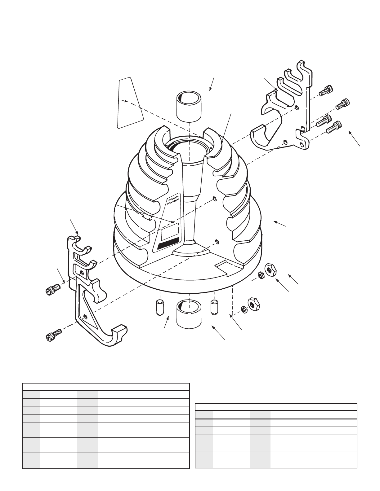
Figure 2
Shoe Subassembly
8
10
11
9
3
GB
2
4
1
4
Shoe Subassembly
Item # Part # # Req’d Description
1 CL199809K 1 Shoe Bending (Incl. items 7, 8, 9 and 10)
2 CN542005 1 Clamp, IMC (Incl. items 4, 5, 6)
3 CN541005 1 Clamp, EMT (Incl. items 4, 5, 6)
4 Common 6 5⁄8" -18 x 21⁄4" Plain Alloy Socket Head
Replaceable Part Cap Screw
5 Common 6 5⁄8" Plain Finish Medium Split Lock
Replaceable Part Washer
6 Common 6 5⁄8" -18 Low Carbon Plain Finish
Replaceable Part Finished Hex Nut
6
5
7 7
8
Shoe Subassembly, cont.
Item # Part # # Req’d Description
7 CK691061 2 Pin
8 CL61107 2 Bearing (includes 2)
9 CM126026 1 Instruction Decal - Stub-Up
10 CM127026 1 Instruction Decal - Offset
11 CM627028 2 Insert, Shoe
4
Page 5

1
2
3
5
6
9
8 8
8
7
1
1
B2000CK
Clamp kit
2
CM802950N
Knob Sub Assembly Kit
3
CM767108
Washer
4
CM801950
Upper Plate Assembly
5
B2000-TRK
Trip Ring Assembly Kit
6
CM803950N
Actuator Kit
7
B2000LSK
Limit Switch Kit
8
DA9687372
Limit Switch (3-Pack)
10
CM593026
Pipe size decal EMT
11
CM594026
Pipe size decal Rigid/IMC
12
ZCF679220
Plate Assembly Kit
12
11
10
4
(Incl. #10
& #11)
Figure 3
Limit Switch Assembly
Limit Switch Assembly
Item # Part # Description
1 B2000HCK Clamp Kit
ZCM793055N Thread Locker (for #1) not pictured
2 CM802950N Knob Sub Assembly Kit
3 CM767108 Washer
4 CM801950 Upper Plate Assembly
5 B2000-TRK Trip Ring Assembly Kit (Incl. #10 & #11)
6 CM803950N Actuator Kit
7 B2000LSK Limit Switch Kit
8 DA9687372 Limit Switching (3-Pack)
9 CM797950KW Plate Assembly Kit
10 CM593026 Pipe size decal EMT
11 CM594026 Pipe size decal Rigid/IMC
12 ZCF679220 Springs
5
Page 6
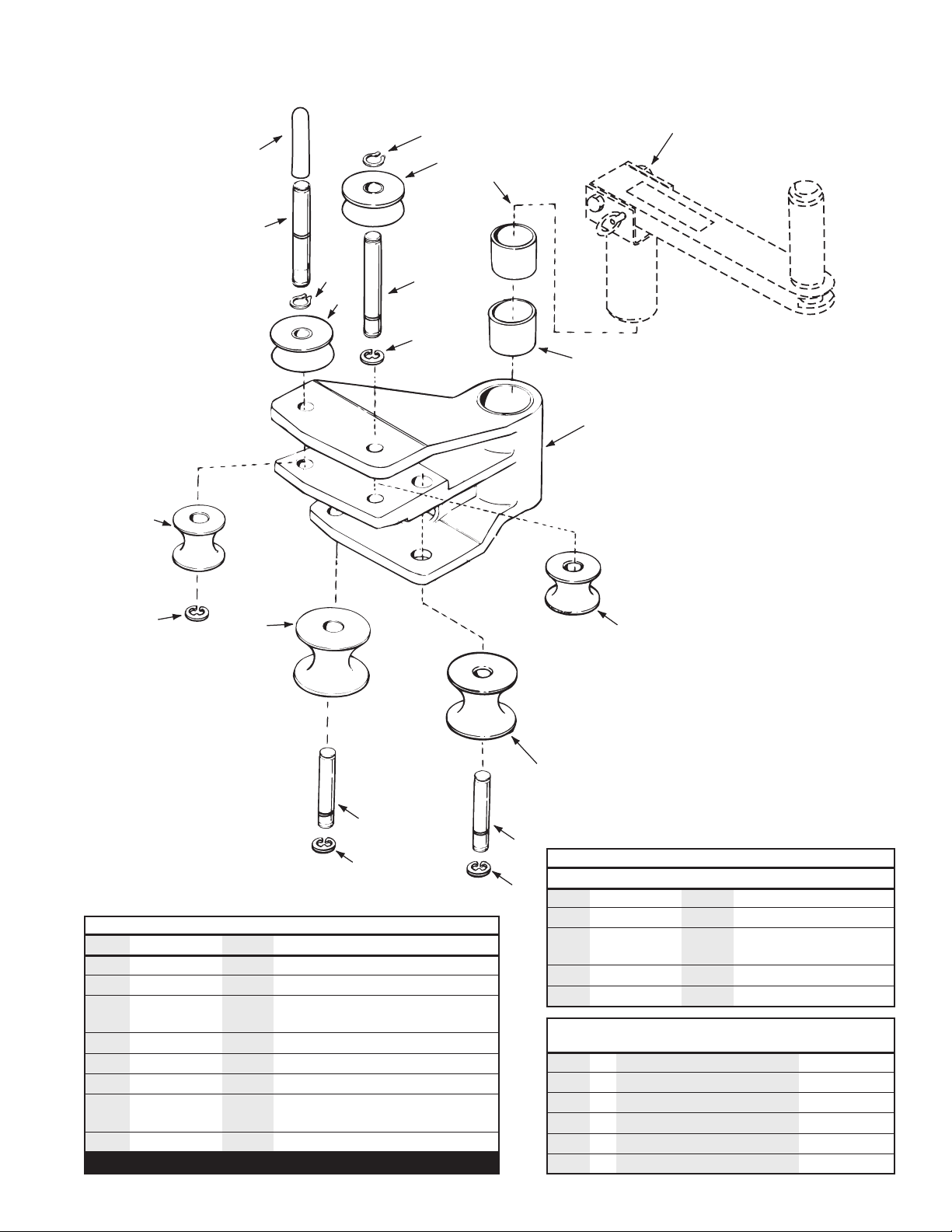
Figure 4
7
7
7
10
10
8
5
3
9
2
6
7
3
9
11
2
1
4
5
13
12
Roller Housing Assembly – CU295900K
NOTE: Item 11 is a separate
assembly not included with
the roller housing (Figure 5).
Roller Housing Assembly-CU295900, cont.
Item # Part # # Req’d Description
9 CU300281 2 11⁄4" Roller (Set of 2)
Roller Housing Assembly-CU295900K
Item # Part # # Req’d Description
1 CU296037K 1 Housing, Roller
2 CL61107 2 Bearing
3 Common Repl.
Part
4 CU299281 1 11⁄2" Roller
5 CU298281 2 2” Roller (Set of 2)
6 CN452104K 1 Shaft, Roller
7 Common Repl. 4
Part
8 CU319281 1 11⁄2" Roller
*When the housing is ordered, the bearings will be pre-installed.
6
*
7
⁄8" External Retaining Ring
7
⁄8" Carbon Spring Steel E-Clip
10 CU297104 2 Shaft, Roller
11 CK994900 1 Upper Roller Assm
(see Figure 5)
12 DC694104 1 Axle
13 CL343550 1 Grip, Handle
B2000-RK Kit includes:
Part#
#4
Roller and Ring Kit
11⁄2" Roller
1
Qty
#5 2" Roller (Set of 2)
#8 11⁄2" Roller
#9 11⁄4" Roller (Set of 2)
#3 7⁄8" External Retaining Ring
#7 7⁄8" Carbon Spring Steel E-Clip
2
1
2
2
4
Page 7

Figure 5
Upper Roller and Handle Assembly – CK994900
4
1
2
3
4
11
10
9
5
Upper Roller and Handle Assembly-CK994900
Item # Part # # Req’d Description
1 Common Repl. 1 1" External Retaining Ring
Part
2 CK569108 1 Washer
3 CK575281K 1 1⁄2"-1" Roller
4 CK295107 2 Bearing (Set of 2)
5 CL30900 1 Roller Axle Assembly
6 Common Repl. 1
Part
7 CL662950KW 1 Cam Shaft
8 CK693107 2 Bearing (Set of 2)
9 Common Repl. 1
Part Zinc Plated Hex Bolt
10 Common Repl. 1 3⁄8" - 16" Lock Nut- Nylon
Part
11 Order Kit LK15 1 Decal, Caution
12 Common Repl. 1 3⁄8" - 16 x 1" 1g. Low Carbon Hex
Part Head Cap Screw, Zinc Plated
13 Common Repl. Part 1 5⁄16" Zinc Plated USS Flat Washer
*
*
These items come with bearings installed.
*
3
⁄8" x 3" Zinc Coherless Hitch Pin
3
⁄8" -16 x 3" A307A Low Carbon
12
13
6
7
8
8
7
Page 8

17
Figure 6
Sprocket Housing
Assembly - DA7058900
31
33
11
36
32
18
19
14
2
12
41
19
21
16
13
46
15
48
47
23
26
22
27
38
47
39
37
40
22
10
23
30
24
42
43
44
45
35
34
28
20
29
25
1
20
Sprocket Housing Assembly - DA7058900
Item # Part # # Req’d Description
1 CL310014 1 Drive Belt
2 CL306900 Includes:
1 Tensioner Assembly
1 Snap Ring
1 Roller
1 Bearing
1 Washer, Thrust
1 Tensioner Weldment
1 Spring
1 Shaft Tensioner
1 Nut, .375-16
10 CL335066 1 Chain, .375 Pitch
11 CW172104 1 Shaft, Roller Housing
12 C550357 1 Gasket, Motor
13 Common Repl. 1 Screw (10-32)
Part
14 CL43259 1 Motor Assembly
15 CL674096 1 Connector
16 CL673228 1 Conduit, Flexible
17 CL675096 1 Connector
18 Common Repl. 4 3⁄8" - 24 x 1" Grade S Plain Finish
Part Hex Cap Screw
19 Common Repl. 5 3⁄8" Plain Finish Medium Split
Part Lock Washer
20 CL54108 2 Washer, Thrust
21 CL656108 1 Bearing
22 Common Repl. 2 1⁄2" - 30 x 3" Grade 5 Plain Finish
Part Hex Cap Screw
23 Common Repl. 4 1⁄2" Belleville Washer
Part
24 CU541950W 1 Sprocket Assembly w/ Bearings
*
*
Sprocket Housing Assembly - DA7058900, cont.
Item # Part # # Req’d Description
25 CL53107 2 Bearing
26 CL12108 1 Washer
27 Common Repl. 1 3⁄8" - 16 x 2" Grade 5 Zinc Plated
Part Hex Cap Screw
28 CL334066 1 Chain, .625 Pitch
29 CU542950K 1 Sprocket Assembly w/ Bearings
30 CL670107 2 Bearing
31 CU674104 1 Shaft, Shoe
32 SHM115 1 Housing, Sprocket
33 CL309104 1 Shaft, Sprocket
34 CL667950KW 1 Sprocket Assembly w/ Bearings
35 CL53107 2 Bearing
36 CL224028 1 Stop Screw
37 CL669101 1 Locking Plate
38 Common Repl. 1 5⁄16" - 24 x 1⁄2" LG Grade 5 Med.
Part Carbon Stl. Zinc Plated
39 Common Repl. 1 5⁄16" Zinc Plated USS Flat Washer
Part
40 Common Repl. 1 1⁄4" Plain Finish USS Flat Washer
Part
41 CL311019 1 Pulley, 10 Groove
42 DA6153006 1 Connector (Body 40) - limit switch
43 CM26006 8 Terminal, Female - limit switch
44 CM33006 1 Connector (M-1) - motor
45 CM28006 2 Terminal, Female - motor
46 Common Repl. 1 #10 -32 x 3⁄32" LG.
Part
47 CU675108 2 Washer
48 Common Repl. 1 CAP
Part
*
*
*These items come with bearings installed.
8
Page 9
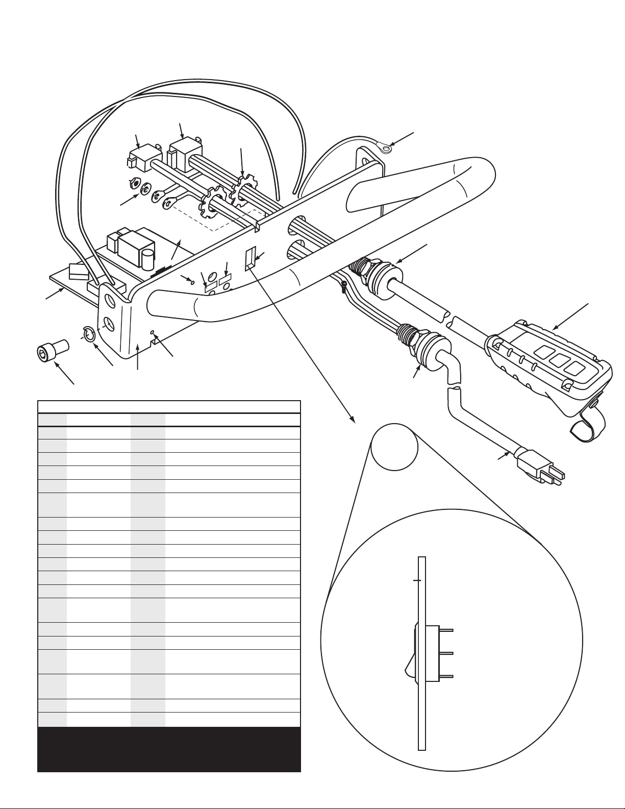
Figure 7
Handle
Faceplate
White Wire
Note: Numbers molded
onto switch by the terminal
verify these before
attaching wires
Black Wire
to Circuit Board
Black Wire from
Power Plug
1
2
3
Handle and Control Circuit Assembly – HC12
7, 8
6
6
19
1
10
9
18
11
13
16
17
3, 4
12
HC12 Contents
Item # Part # # Req’d Description
1 CJ458885 1 Locknut
2 CM178647SR 1 Plug Assembly
3 CM32006 1 Receptacle, Power Cord
4 CM25061 2 Pin, Cord Receptacle
5 PO5C 1 Pendant Station Assm
6 Common Repl. 3 #6 -32 X 3⁄8" LG. Button Hd.
Part Cap Screw
7 DA6152006 1 Receptacle, Pendant
8 CM27061 8 Pin, Receptacle
9 LK15 1 Decal, Kit
10 LK15 1 Decal, Kit
11 EC2006 1 Circuit Board
12 H905 1 Handle Assembly
13 Common Repl. 4 1⁄2" - 13 x 7⁄8" Alloy Plain Finish
Part Socket Head Cap Screw
14 DA7046900 1 Wire, Jumper
15 F1550 1 Grip, Cord
16 Common Repl. 1 #10 Hi-Collar Helical Spring
Part Lock Washer
17 Common Repl. 4 1⁄2" Plain Finish High Collar
Part Lock Washer
18 CB25 1 Switch
19 RA19 1 Braking Resistor
Item 3 is packed with item 4 loose.
Item 7 is packed with item 8 loose.
Instructions provided for assembling loose connectors.
DA 7070900 Limit Switch Jumper (not shown) (for older units)
14
15
15
2
5
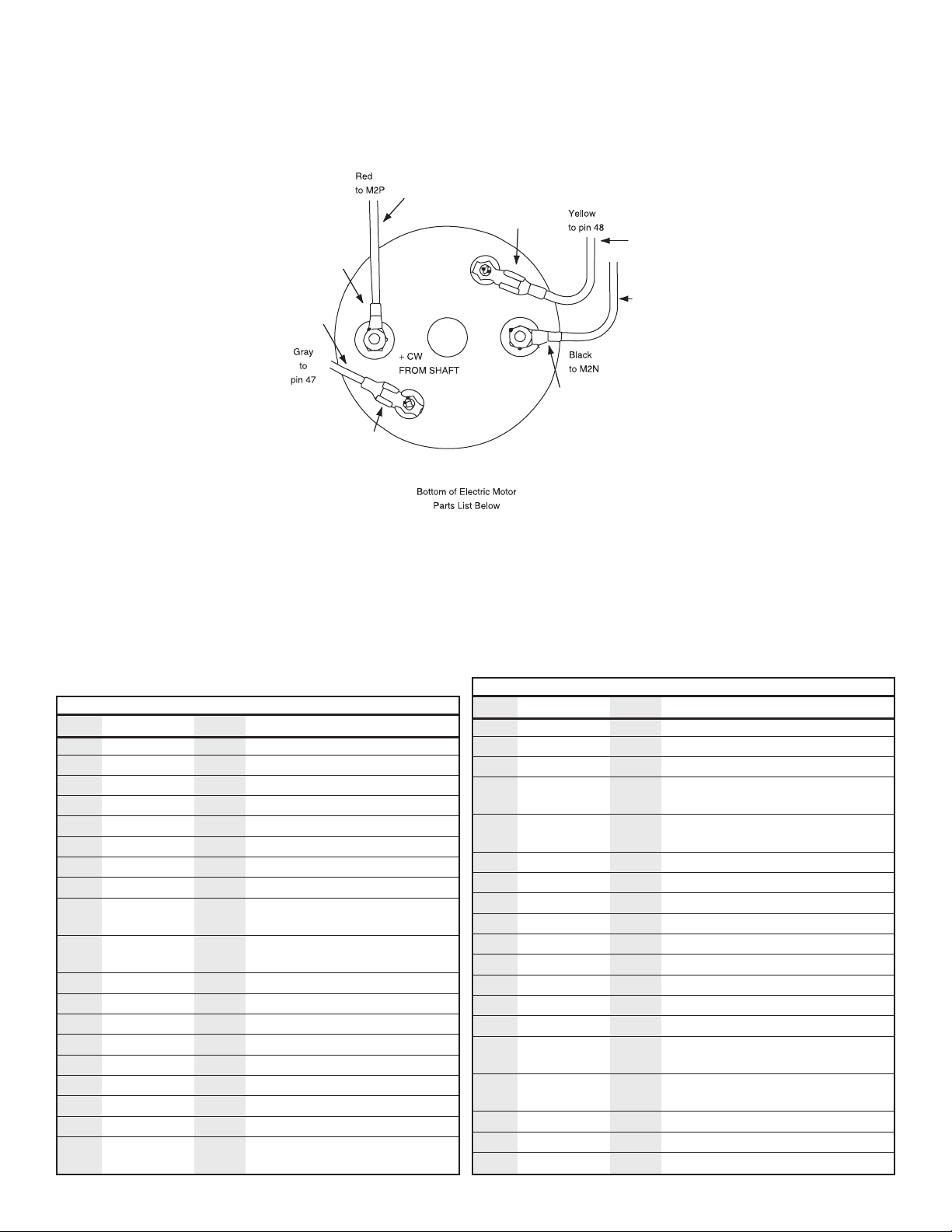
Wiring Diagram
for BMK3 Switch
9
Page 10

BEND LIMIT SWITCH
Wiring Schematic
GREEN
(OPEN)
ORANGE
NOTE: 2-LONG STUDS FOR COVER MOUNTING ONLY
AZ
BLACK
BLOCK MOUNTING
BOTTOM OF MOTOR
YELLOW
GREY
(OPEN)
BLACK
RED
WHITE
(43)
(46)
ZERO STOP SWITCH
BLACK
ORANGE GREEN
RED
YELLOW
(42)
BLACK
(45)
(48)
RETURN LIMIT SWITCH Typical Switch Contacts
WHITE
(OPEN)
BLUE
(41)
BLUE
(44)
GREY
(47)
CONNECTOR TO CIRUIT BOARD
COMMON
NORMALLY OPEN
NORMALLY CLOSED
RED
MALE CONNECTOR
POWER CORD
FEMALE CONNECTOR
RED
BLACK
RED
BLACK
CIRCUIT BOARD
P5
P7
P8
P6
WHITE
WHITE
FEMALE CONNECTOR
BLACK
WHITE
BLACK
BMK3 SWITCH
BLACK
BLACK
WHITE
BLACK
MALE CONNECTOR
WHITE
10
Page 11

NOTES
11
 Loading...