

Troubleshooting Guide
B2000 Cyclone® Bender
GAR_TL_045_0717
SERVICE INSTRUCTIONS
These Service instructions are intended for use by a qualified personal at Authorized Gardner Bender Service
Centers. Users of Gardner Bender equipment should see the bender instruction sheet for installation, operation and
maintenance information.
SAFETY ISSUES
WARNING is reserved for conditions and actions that can cause serious or fatal injury.
CAUTION is reserved for conditions and actions that can cause injury or instrument damage.
WARNING:
• Do not locate the bender on damp or wet surfaces. Do not stand on damp or wet surfaces when repairing
or operating the bender.
• To avoid electrical shock, always unplug the bender power cord before removing end plates, motor or any electrical wiring.
CAUTION:
• To avoid physical injury, use two people to remove and install the bending shoe or to move it from place to place.
• Keep hands, clothing and electrical power cords away from moving rollers, bending shoe and exposed gears.
• Prior to installation: apply a coat of molycoat or equivalent to all shafts. When installing shafts,
use soft head mallets to seat in position.
REQUIRE TOOLS AND TEST EQUIPMENT
• Torque Wrench
• Allen Wrench
• Open Wrench ½" and 9/16"
• Sockets
• Lithium Grease
• Soft Head Mallet
TABLE OF CONTENTS
1.0 Troubleshooting Guide .........................................2-6
2.0 Pendant Troubleshooting ........................................ 6
3.0 Disassemble Instructions ....................................... 7
Limit Switch ..................................................... 7
Roller Housing ................................................. 7
Bender Shoe .................................................... 7
Circuit Board .................................................... 7
Electric Motor .................................................. 7
Drive Sprocket Assembly ................................ 8
4.0 Reassembly Instructions ........................................ 8
Drive Belt and Sprockets ................................ 8
Motor Assembly .............................................. 9
Shoe Shaft ....................................................... 9
Roller Housing ................................................. 9
Prinited Circuit Board ...................................... 9
Limit Switch Assem/Wiring ............................. 9
• 2" EMT and Rigid Conduit
• Silicone sealant
• Multimeter
• Strap Wrench
• Repair Parts Sheet
• Instructions Manual
5.0 Zero Adjustment .................................................... 10
6.0 Parts Breakdown ................................................... 11
B2000 Bender ................................................ 11
Bottom of Electric Motor .............................. 12
Shoe ............................................................... 13
Limit Switch ................................................... 14
Roller Housing ............................................... 15
Upper Roller / Handle ................................... 16
Sprocket Housing .......................................... 17
Handle / Control Circuit ................................18
7.0 Wiring Schematic .................................................. 19
8.0 Limit Switch Wiring Diagram ................................ 20
9.0 Maintenance .......................................................... 21
10.0 Interchangeable Part Compatibility ..............21-23
1

1.0 TROUBLESHOTTING GUIDE
*Note: Troubleshooting or maintenance that requires the B2000 to be disassembled in any way should be done by a
professional indicated by Gardner Bender to avoid permanent damage to the machine. Contact nearest Gardner Bender
Service Center for guidance.
PROBLEM POSSIBLE CAUSE ACTION
Bending shoe does not
move when switch is in
bend or return position.
Roller Housing and
Upper Roller do not
properly lock the
conduit into place.
Circuit break / power
switch in the off position.
No power to bender. Check for voltage at power source. Use 110 VAC, 15 amp outlet.
Blown Fuse.* *THIS PROBLEM WILL NOT OCCUR ON MODELS B2000-5 THROUGH
12V DC power supply
failed.
Remote pendant
wiring harness is
malfunctioning.
Power circuit on P.C.
board is malfunctioning.
Motor overload or/
overheated.
Upper Roller pivot is in
incorrect position.
Incorrect rollers used. If the Roller Housing (Part Number – CU295900K) has been disassembled in
Rollers are damaged Replace damaged rollers.
Check that power switch (Part Number – CB25) is in the “ON” position. When
the bender is ON, the two LEDs on the Rear Handle End Plate (Part Number –
HC12) will flash red, then green to indicate normal function. The green power
light on the control pendant (Part Number – PO5C) should be lit.
B2000-7 (SERIAL NUMBERS BEGINNING WITH LETTERS “F” - “K” OR
BENDERS MANUFACTURED BETWEEN 2001 AND 2007). THESE MODELS
DO NOT HAVE A FUSE.
Inspect 15 amp fuse and perform continuity check for a short.
If no continuity, replace fuse with new 15 amp, 125 volt fuse.
Fuse located behind handle mounting plate in the left corner of the
control panel. Refer to “Circuit Board” in “DISASSEMBLY” section (page 7)
for instructions.
Unplug bender power cord. On P.C. board, remove cover on plug.
Connect positive meter lead on black wire and negative lead on green wire.
Plug in the power cord.
Meter should indicate 12V DC.
If not, replace P.C. board, Part Number- EC2006 or HC12
Refer to “Circuit Board” in “DISASSEMBLY” section (page 7) for instructions.
Remote pendant wiring in the harness may be pinched or cut in a way that
causes bending to malfunction despite the indicator LEDs on Rear Handle
End Plate and Remote Pendant illuminating.
Replace wire harness. (Refer to Repair Parts List for illustration and
additional part numbers).
Refer to “Circuit Board” in “DISASSEMBLY” section (page 7) for instructions.
Control circuit is not activating bender.
Replace P.C. board, Part Number- EC2006 or HC12
Allow time for motor to cool. Activate bender.
If motor will not run, perform continuity check. If there is continuity, motor
is damaged and must be replaced, Part Number – CL43259
Refer to “Electric Motor” in “DISASSEMBLY” section (page 7) for instructions.
If the Upper Roller has been disassembled in the past, the pivot may be in the
wrong position.
While facing the B2000 push handles, remove the Upper Roller (Part Number –
CK994900) and look down the bearing shaft. There will be an off-center hole
at the bottom of the bearing. If the Upper Roller is correctly installed facing to
the right, this hole should be closer to you to ensure that the pivot is in
the right position.
Refer to “Roller Housing” in “DISASSEMBLY” section (page 7) for instructions.
the past, the rollers may have been incorrectly reassembled. The middle set of
1½" nylon rollers (Part Numbers – CU299281 and CU319281) must be placed
in the correct position and are not interchangeable. The upper set of 1¼"
rollers (Part Number – CU300281) can be swapped and the lower set of
2" rollers (Part Number – CU298281) can be swapped.
Refer to “Roller Housing” in “DISASSEMBLY” section (page 7) and “Roller
Housing” in “RE-ASSEMBLY” section (page 9) for instructions on assembling
the rollers.
Refer to “Roller Housing” in “DISASSEMBLY” section (page 7) for instructions.
2

Drive belt tensioning
seems loose.
Bend switch does not
function, return switch
functions.
Bend function works,
return switch does not.
Belt is worn out. Belt may be worn or damaged and must be replaced,
Part Number – CL310014.
Refer to “Drive Sprocket Assembly” in “DISASSEMBLY” section (page 8)
for instructions.
Tensioner failure. Tensioner may be damaged and must be replaced, Part Number – CL306900.
The motor must be removed in order to remove the tensioner. Refer to
“Electric Motor” in “DISASSEMBLY” section (page 5) for instructions.
Motor pulley is lose. If the motor has been disassembled in the past, thread-locking fluid may
not have applied to the containing screw of the motor pulley (Part Number –
CL311019) when reassembling the motor assembly (Part Number – CL43259).
Apply thread-locking fluid on containing screw and assemble it to the
motor pulley.
Refer to “Electric Motor” in “DISASSEMBLY” section (pages 7 & 8)
for instructions.
Remote pendant
bend switch or wiring
inoperative.
Unplug bender power cord, test for continuity at hard¬ness to pendant. Attach
leads to black and white wires. Press bend switch. If no continuity, check
switch under pendant cover. Place ohm meter on leads for black wire and
white wire. Depress bend switch.
If continuity exists, replace switch, Part Number - DA9687372.
If no continuity, wire harness is faulty.
Refer to “Limit Switch” in “DISASSEMBLY” section (page 7) for instructions.
Bend limit switch or
harness to limit switch
is malfunctioning.
Unplug bender power cord. Perform continuity check on green and orange
wires. Press bend limit switch actu¬ator tab.
If continuity exists, replace switch, Part Number - DA9687372.
If no continuity, check wiring harness. (Refer to Repair Parts List for
illustration and additional part numbers).
If no continuity exists on wire harness, it must be replaced.
Refer to “Limit Switch” in “DISASSEMBLY” section (page 7) for instructions
Plunger on bend limit
switch is not being
tripped by the shoe post.
Remove shoe indicator plate (Part Number – CM801950). Observe the shoe
post as it passes the bend limit switch (Part Number - DA9687372). The shoe
post should trip the plunger on the bend limit switch as it passes over the limit
switch.
If the shoe post is not tripping the plunger, replace the limit switch, Part
Number- DA9687372.
Refer to “Limit Switch” in “DISASSEMBLY” section (page 7) for instructions.
Printed circuit board
malfunctioning.
Pendant return switch is
malfunctioning.
Replace P.C. board, Part Number- EC2006 or HC12
Refer to “Circuit Board” in “DISASSEMBLY” section (page 7) for instructions.
Unplug bender power cord. Perform continuity check on pendant return
switch. Attach leads to black wire and white wire, depress return switch.
*The colors described here are not present on the model B2000-7 and B20008 pendant harness (B2000 SERIAL NUMBERS BEGINNING WITH LETTERS
“J” - “N” OR BENDERS MANUFACTURED AFTER 2007). However, the same
troubleshooting actions should be taken.
If continuity exists, replace switch, Part Number - DA9687372.
Refer to “Limit Switch” in “DISASSEMBLY” section (page 7) for instructions.
Wiring is malfunctioning. If no continuity, check wire harness. Attach ohm meter leads to orange
and blue wires. Depress return switch.
If no continuity; replace wire harness, Part Number – CL¬712647SR.
Refer to “Drive Sprocket Assembly” in “DISASSEMBLY” section (page 8)
for instructions.
3

Bender shoe will not
return when pressing
return and jog button.
Bender shoe
successfully returns to
zero, indicator light on
top of Pendant Control
malfunctions and does
not light.
Bender consistently
develops over bends.
Jog button
malfunctioning.
Wire harness to pendant
damaged.
Pendant damaged or
malfunctioning.
Zero limit switch is
malfunctioning and is
not receiving voltage.
Harness to switch is
malfunctioning and is
not receiving voltage.
Bend angle is not
correctly indicated.
Bender zero adjustments
are necessary.
Bender angle
adjustments are
necessary.
Unplug bender power cord. Perform continuity check on wire harness.
Attach leads to red and green wires, Depress override (jog) button.
*The colors described here are not present on the model B2000-7 and
B2000-8 pendant harness (B2000 SERIAL NUMBERS BEGINNING WITH
LETTERS “J” - “N” OR BENDERS MANUFACTURED AFTER 2007).
However, the same troubleshooting actions should be taken.
If continuity exists, check jog switch in pendant control, (Parts Not Available).
Remove cover, place leads on red and green wires at switch. Depress jog
switch. If there is continuity, replace switch (Parts Not Available).
Refer to “Circuit Board” in “DISASSEMBLY” section (page 8) for instructions
If no continuity exists, fault lies in wire harness.
Replace wire harness. (Refer to Repair Parts List for illustration and
additional part numbers).
Refer to “Circuit Board” in “DISASSEMBLY” section (page 7) for instructions.
Replace pendant switch, Part Number – PO5C
If model B2000-4 or older (SERIAL NUMBERS BEGINNING WITH LETTERS
“A” - “E” OR BENDERS MANUFACTURED BEFORE 2001), customer may
need to upgrade to current model B2000. Older model pendant switch is no
longer available.
For models B2000-5 and B2000-6 (SERIAL NUMBERS BEGINNING WITH
LETTERS “F” - “H” OR BENDERS MANUFACTURED BETWEEN 2001 AND
2004), customer may be able to adapt new pendant (P05C) to older models.
Unplug bender power cord. Perform continuity check on harness from pendant
control. Attach leads to black and red wires.
Refer to “Circuit Board” in “DISASSEMBLY” section (page 5) for instructions.
If continuity exists, check the zero limit switch (see illustration in Repair Parts
List).
Attach the leads to black and red wires at the limit switch. Depress limit switch
actuator tab. If continuity exists, replace switch, Part Number- DA9687372.
Refer to “Limit Switch” in “DISASSEMBLY” section (page 7) for instructions.
Unplug bender power cord. Perform continuity check on wire harness
from limit switch.
If no continuity exists, the wire harness is malfunctioning.
Remove and strip wire harness wire ends, crimp on female terminals
(Part Number – 21-161F), and reconnect terminals to limit switches.
If problem continues, replace wire harness.
In order to replace the limit switch wire harness, the following components
need to be disassembled: bender shoe (item #1), sprocket (item #8),
end plate (item #26), and handle (item #38). Please refer to Figure 1 to
identify listed parts.
Refer to “Bender Shoe”, “Drive Sprocket”, and “Limit Switch” in
“DISASSEMBLY” section (pages 7 & 8) for instructions.
Ensure that the flat edge of the pointer (Part Number – 802950N) is on a line
indicating the exact degree of bend desired, not the angled edge. Failure to do
this will lead to inaccurate bends.
Refer to Instruction Sheet for operation instructions.
Ensure bender zero adjustment has been performed. This is required
after every re-assembly.
Refer to “ZERO SET ADJUSTMENT” section (page 10) for mechanical
adjustment instructions.
Differences in conduit characteristics and other variations can lead to incorrect
scale indications. Loosen the size scale (for type material being bent) mounting
screws. Slide the scale clockwise as many degrees as the over bend (if bend is
5° over, move indicator 5° clockwise). The degree of movement is observed by
watching one of the size marks as it moves past the angle disc scale. Tighten
the mounting screws.
Refer to Instruction Sheet for more Angle Adjustment instructions.
4

Bender consistently
develops over bends
Bender does not stop
at selected bend angle.
During return function,
bender shoe does not
stop at zero point.
Bender shoe does not
stop rotating in both
the return and bend
directions.
Braking resistor on P.C.
board is malfunctioning.
P.C. board circuit is
malfunctioning.
Bender is incorrectly
set up.
Bend limit switch is not
being actuated by shoe
post.
Bend limit switch is
malfunctioning.
Braking resistor is
malfunctioning.
Brake circuit (P.C. board)
is malfunctioning.
Plunger on return
limit switch is not
being tripped by the
trip ring tab.
Bend limit switch is
malfunctioning.
Return limit switch is
malfunctioning.
Brake resistors are
malfunctioning.
Limit switches
assembled incorrectly
on the switch arm.
Unplug bender power cord. Perform resistance measurements on braking
resistor. Remove chassis from rear of bender. Attach ohm meter across to
brown and gray wires.
If meter reads above 11 ohms, replace resistor.
Refer to “Circuit Board” in “DISASSEMBLY” section (page 7) for instructions.
Remove and replace P.C. Board, Part Number- EC2006 or HC12.
Refer to “Circuit Board” in “DISASSEMBLY” section (page 7) for instructions.
Ensure bender angle adjustment and zero adjustment has been performed.
This is required after every re-assembly.
Refer to “ZERO SET ADJUSTMENT” section (page 10) for mechanical
adjustment instructions. Refer to Instruction Sheet for Angle Adjustment
instructions and correct set up instructions.
Remove shoe indicator plate. Observe the tabs as they pass the bend limit
switch.
Adjust switch until tabs correctly contact the posts.
Refer to “Limit Switch” in “DISASSEMBLY” section (page 7) for instructions.
Unplug the bender power cord. Attach leads to orange and green wires at the
switch. Continuity should exist. Push the actuator tab (on the switch).
Continuity should be broken. If not, replace the switch.
Refer to “Limit Switch” in “DISASSEMBLY” section (page 7) for instructions.
Unplug the bender power cord. Perform resistance measurement on braking
resistor. Attach leads across terminals.
A 9-11 ohms (+ 1 ohm) resistance is normal. Other readings are unacceptable.
Replace braking resistor, Part Number – RA19.
Refer to “Circuit Board” in “DISASSEMBLY” section (page 7) for instructions.
If all other tests are positive, replace P.C. board, Part Number– EC2006
or HC12.
Refer to “Circuit Board” in “DISASSEMBLY” section (page 7) for instructions.
Remove limit switch assembly. Observe tab to return limit switch contact.
If switch is not contacting tab, adjust switch position.
Refer to “Limit Switch” in “DISASSEMBLY” section (page 7) for instructions.
If post to switch is correct, perform bend limit switch continuity check. Attach
leads to orange and green wires. Press limit switch tab.
Continuity should result. If not, replace switch.
Refer to “Limit Switch” in “DISASSEMBLY” section (page 7) for instructions.
Unplug the bender power cord. Perform return limit switch continuity check.
Attach leads to white and blue wires.
Continuity should be broken. If not, replace return limit switch.
Refer to “Limit Switch” in “DISASSEMBLY” section (page 7) for instructions.
Unplug the bender power cord. Perform resistance measurement on each
resistor. Place ohm meter leads on gray and brown wires.
Meter should read 9-11 ohms. If reading is over 11 ohms, replace resistor.
Refer to “Circuit Board” in “DISASSEMBLY” section (page 7) for instructions.
If the Limit Switch has been disassembled in the past, the switches may have
been reassembled incorrectly on the switch arm. The switch arm must have
two limit switches (blue face, facing away from arm) on the long side of the
arm, and one limit switch (black face, facing away from arm) on the short side
of the arm.
Refer to “Limit Switch” in “DISASSEMBLY” section (page 7) for instructions.
5
Bend function works,
Wiring Schematic
return function results
in bending direction.
Return function works,
bend function results in
shoe moving in return
Direction circuit on P.C.
board is malfunctioning.
Brake circuit on P.C.
board is malfunctioning.
Replace P.C. board.
Refer to “Circuit Board” in “DISASSEMBLY” section (page 7) for instructions.
If all other tests are positive, replace P.C. board.
Refer to “Circuit Board” in “DISASSEMBLY” section (page 7) for instructions.
direction.
Return function works.
Depressing bend
switch, shoe moves
Direction circuit on P.C.
board is malfunctioning.
Replace P.C. board.
Refer to “Circuit Board” in “DISASSEMBLY” section (page 7) for instructions.
in return.
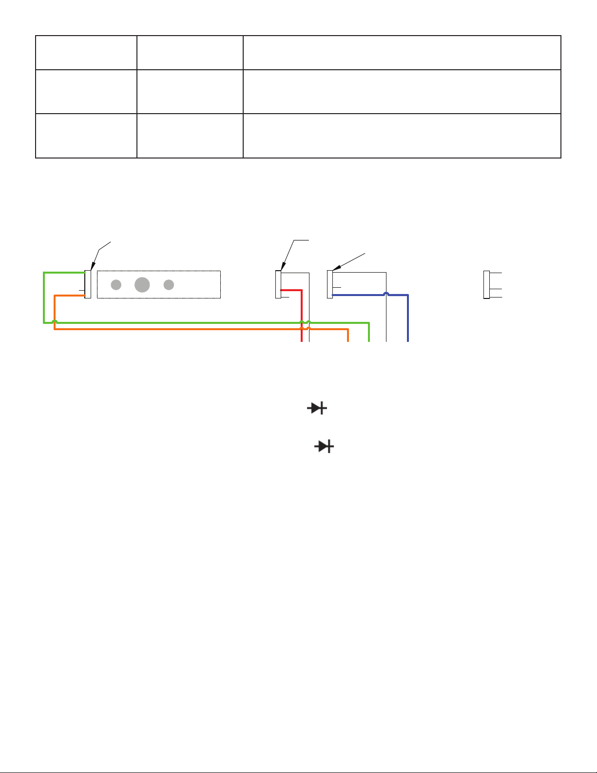
2.0 PENDANT (P05C) TROUBLESHOOTING
1. Verify continuity for both wires traveling from the zero limit switch down to the wire harness.
GREEN
(OPEN)
ORANGE
BEND LIMIT SWITCH
BLOCK MOUNTING
(OPEN)
BLACK
RED
ZERO STOP SWITCH
WHITE
(OPEN)
BLUE
K
RETURN LIMIT SWITCH Typical Switch Contacts
COMMON
NORMALLY OPEN
NORMALLY CLOSED
2. Verify that the black wire goes to the pin on the limit switch that is separate from the other two, and that the red wire
is connected to the middle pin.
3. Test Zero Light - Take a multimeter and set it to the diode (
) function and place the red lead on the orange wire
in the harness and the black lead to the red (pink) wire in the harness. This should illuminate the green Zero LED
4. Test Power LED - Take a multimeter and set it to the diode (
) function and place the red lead on the orange wire
and black lead on the yellow wire. This should illuminate the red Power LED.
5. Test Bend Button - Set a multimeter to the continuity or ohms function. Place one meter lead to the pin of the Black
wire in the pendant wire harness, and place the other lead on the pin for the Blue with Black strip wire. While the
probe tips are making contact with the pins in the harness, press the bend button. When the button is pressed, 0
Ohms and/or the continuity buzzer should go off.
6. Test Return Button - Set a multimeter to continuity or ohms function. Place one meter lead on the pin of the Black
wire in the pendant wire harness. Place the other meter lead to the pin of the Blue wire in the harness. With the
probes still making contact with the pins, press the Return button. When the button is pressed, 0 Ohms and/or the
continuity buzzer should go off.
7. Test Jog Button - Set a multimeter to the continuity or Ohms function. Place one meter lead to the pin of the Black
wire in the pendant wire harness, and place the other lead on the pin for the Brown wire. While the probe tips are
making contact with the pins in the harness, press the bend button. When the button is pressed, 0 Ohms and/or the
continuity buzzer should go off.
6

3.0 DISASSEMBLY INSTRUCTIONS
IMPORTANT: To avoid unnecessary service, the bender
should be tested prior to any service work. Please refer
to the maintenance section in the instructions manual and
Troubleshooting section.
Limit Switch (Figure 3)
1. Prior to removing components of the limit switch
and angle adjustments, the bending shoe, trip ring
and sprocket housing must be marked to aid in
re-assembly.
2. Position the bending shoe to the zero point by
pressing the pendant in “RETURN. Continue holding
the switch until the shoe stops and the zero light
comes on.
3. Unplug the bender power cord.
4. Scribe a mark on the side of the trip ring (Figure 1)
and a matching mark on the bending shoe.
5. Scribe a mark on the lower portion of the bending
shoe and on the sprocket housing (Figure 1).
6. Remove the silicone packing from the trip ring
mounting screws (Figure 3). Remove the mounting
screws and the top plate assembly (Figure 3), the size
indicator plates must not be removed.
7. Remove and tag the wires attached to the limit
switches (Figure 3). Leave the switches (Figure 3)
attached unless they require replacement.
8. Remove the springs and the three screws from the
plate assembly (Figure 3).
9. Leave actuator and clamp attached to upper plate
assembly unless damaged.
10. Examine all components for signs of wear or damage.
Use troubleshooting procedures to electrically check
switches. Repair or replace items that are worn,
damaged or non-functional.
11. Refer to “RE-ASSEMBLY” section of this manual.
Roller Housing (Figure 4 & 5)
1. Remove the pin (Figure 5 Item #6) securing the upper
roller arm (#5). Remove the nut (Figure 5 Item #10)
and remove the cap screw (Figure 5 #9) securing the
arm in the Cam Shaft (Figure 5 Item #7).
2. Remove the cap screw (Figure 5 Item #12) and the
washer (Figure 5 Item #13). Lift the roller housing
(Figure 4 Item #1) from the shaft. Remove the thrust
washers (Figure 1 Item #21) and the shims (Figure 1
Item #22).
3. Inspect all rollers, the housing and shaft for wear and
damage. Replace worn or damaged items.
4. All nylon rollers should be secured in the housing by
retaining rings around the roller shafts (Figure 4). Be
sure that the correct rollers are reassembled in the
exact location they were in originally. All new rollers
contain factory installed bearing.
Bender Shoe (Figure 1 & 2)
1. Prior to removing the bending shoe, the limit switch
assembly must be removed. Refer to “LIMIT SWITCH”
in the disassembly procedures.
2. Remove the four bolts (Figure 1 Item #9) and washers
(Figure 1 Item #10) located on the flat portion of each
side of the shoe (Figure 2 Item # 1).
3. Two people are required to lift the bending shoe. Lift
at two places (180° apart) and pull the shoe straight
up until it clears the shoe shaft.
4. Inspect the shoe for worn grooves, cracks or other
damage. Each conduit groove should be checked for
wear by placing a piece of conduit (of correct size and
material) into the groove. It should fit easily without
excessive gaps above, below or behind it.
5. If shoe damage is suspected, a dye penetrate may be
required to locate cracks in the casting.
6. Refer to Re-Assembly procedures.
Circuit Board (Figures 7 / Insert B)
1. The printed circuit board is mounted inside of the
sprocket housing. Access is gained by removing the
handle assembly.
WARNING: To avoid electrical shock, unplug the
bender power cord prior to removing the handle and
access plate.
2. Remove the four screws and washers (Figure 7 Items
#13 & 17).
3. Remove the handle assembly (Figure 1 Item# 38)
NOTE: Hold the handle to prevent it from falling and
causing damage to electrical connectors inside the
sprocket housing.
4. Lower the handle and plate assembly. Unplug the
power cord receptacle (Figure 7 Item #3) from the
P.C. board plug. Unplug the pendant receptacle (Fig.
7 Item #7) from the P.C. board plug.
5. Conduct testing procedures described in the
“Troubleshooting” section. See Insert B for wiring
diagram.
Electric Motor (Figure 6)
WARNING: Unplug bender power cord prior to removing
motor or wiring.
1. Remove acorn nuts securing the motor bottom cover.
2. Remove electrical wires from bottom of motor. Refer
to (Page 14 Insert A).
3. Remove bolt and washer (Figure 6 Item #26 & 27)
which secures the locking plate (Figure 6 Item #37)
to the bottom of the sprocket housing. Remove bolt
(Figure 6 Item #38), lock washer (Figure 6 Item #39)
and washer (Figure 6 Item #40) which secures the
sprocket shaft in the locking place.
4. Rotate the sprocket shaft by placing the locking plate
over the shaft flats. Turn the shaft until the sprocket
belts and chains are loose.
5. Remove the conduit nut (Figure 6 Item #15) from the
motor connection. Slide the flexible conduit out of the
7

elbow and pull the wires out.
6. Remove the rear access plate by removing 4 cap
screws and washers.
7. Remove the four cap screws and washers (Figure 6
Item #18 & 19) securing the motor to the sprocket
housing, Remove the motor, unhook the drive belt
from the motor shaft.
8. Remove the belt tensioner (Figure 6 Item #2) by
removing nut and washer. The tensioner shaft is
spring loaded. Remove the tensioner assembly
spring and shaft from inside the sprocket housing.
Drive Sprocket Assembly (Figure 6)
1. Separate the drive chain (Figure 1 Item #8) by
removing the master link.
NOTE: The master link is assembled with clip on top
– it must be reassembled the same way.
2. Remove drive sprocket (Figure 1 Item #7) from shoe
shaft (Figure 6 Item # 31), Remove spacer (Figure 1
Item #5) and DU Washer (Figure 1 Item #6).
3. Remove dust cap (Figure 1 Item #36) from sprocket
housing.
4. Remove cap screw (Figure 6 Item #22) and washer
(Figure 6 Item #47 / 23). Lightly tap bottom of roller
housing shaft (Figure 6 Item #11) to remove it from
the sprocket housing.
NOTE: Use brass drift pin or leather mallet to remove
shafts.
5. Rotate sprocket (Figure 6 Item # 34) until the master
link for chain (Figure 6 Item #28) appears in the
access opening.
6. Remove the master link and remove the chain from
the sprocket housing.
7. Remove the cap screw (Figure 1 Item #22) and
washer (Figure 1 Item #23 / 47). Carefully remove
shoe shaft (Figure 6 Item #31) by holding the limit
switch wires inside the sprocket housing and lifting
the shaft out of the housing. Remove bearing (Figure
6 Item# 21).
8. While removing the sprocket shaft (Figure 6 Item
#33), hold the sprocket down, tap the shaft (from the
bottom) and remove it from the sprocket housing.
9. Remove sprocket assemblies (#8) and (#9) from the
housing and remove thrust washer (#10).
10. Remove sprocket assembly (#11) and thrust washer
(#12) from the housing.
11. Clean the sprocket housing (inside), wipe away
grease and dirt. Use lower pressure air hose to
remove any accumulation of debris.
12. Clean all sprockets, gear teeth and chains. Check
for worn gear teeth and worn or damaged bearings.
Check chains and drive belt for wear and/or damage.
Replace damaged or worn items.
4.0 RE-ASSEMBLY INSTRUCTIONS
Drive Belt And Sprockets (Figure 6)
1. Position drive belt sprocket (Figure 6 Item #24) and
shoe sprocket (Figure 6 Item #29) on a flat surface.
Connect 3/8” chain (Figure 6 Item #10) to drive belt
sprocket (upper gear) and to shoe bracket (large
lower gear). Insert master link (pin up).
2. Lift the belt sprocket, slip the belt (Figure 6 Item # 1)
under the sprockets and position it in the sprocket
grooves. Lift the shoe sprocket, position the belt so it
is around sprocket shaft boss (Figure 6).
3. Pull the belt tight around the belt sprocket. Fasten
the loose end together with a rubber band to keep
the belt snug on the sprocket.
4. Insert drive sprocket (Figure 6 Item #34) into the
housing (large gear up) and position the gear through
the hole (under bracket). Place small blocks between
the gear and the housing to hold the sprocket against
the inside of the housing.
5. Position shoe sprocket (Figure 6 Item #29) and belt
sprocket into the housing, from the motor end. The
belt sprocket is aligned under the drive sprocket and
the shoe sprocket is positioned under the shoe shaft
hole. The loose belt end belongs toward the motor
end of the housing. Position thrust washer (Figure
6 Item #20) between the belt sprocket and drive
sprocket, bearing surface facing up.
6. Place the thrust washer (Figure 6 Item #20) under the
shoe sprocket.
7. Align drive sprocket (Figure 6 Item #34) and belt
sprocket (Figure 6 Item #24) with the center hold
(under bracket on housing). Place bearing (Figure 6
Item #35) on top of sprocket. Remove blocks.
8. Mark high point on end of sprocket shaft (Figure 6
Item #33). Lubricate shaft with light coat of general
purpose grease. Insert shaft (flats first) through the
sprockets. Drive flush with the top sprocket.
9. Insert cap screw (Figure 6 Item #27) through washer
(Figure 6 #26) and locking plate (Figure 6 Item
#37). Torque to 28 – 32 ft. lb. Install cap screw into
sprocket shaft under housing. Install cap screw
(Figure 6 Item #38) and washer (Figure 6 Item #39
/40) in hole aligned with lock plate slot. Torque to 19
– 21 ft. lb.
10. Mark the middle link of chain (Figure 6 Item #28).
Put the chain over the small (upper) gear teeth of
sprocket (Figure 6 Item #29). Place chain around
large gear of sprocket (Figure 6 Item #34).
11. Install master link through the access hole in the
housing (pins up).
12. Install tensioner assembly by inserting shaft (Figure 6
Item #1) through the inside of the sprocket housing
(threads outward). Assemble the lock washer (Figure
6 Item #2) and nut and tighten.
13. From inside the sprocket housing slide the spring
over the shaft, then slide the tension roller over the
shaft (roller toward drive belt). Place something under
the tension bracket to wedge it in place away from
the drive belt.
8

Motor Assembly (Figure 6 / Insert A)
1. Remove restraint from drive belt.
2. Place gasket (#1) on motor flange. Insert motor into
the sprocket housing. Install one mounting screws
and washers into mounting hole closer to the belt
3. Position the drive belt over the motor pulley. Align the
belt to ride at the same height on the motor pulley
and grooved sprocket.
4. Using a strap tool put it around the motor to help
align the mounting holes with the motor. Install the 3
mounting screws and washers.
5. Remove the wedge from beneath the tension bracket.
The roller should engage the belt.
6. Connect wiring to base of motor. (Figure 1 Insert B).
Shoe Shaft (Figure 6)
1. Position the shoe shaft (Figure 6 Item #31) in the
sprocket housing (Figure 6 Item #32) with the hole for
the wiring facing the hole in the housing.
2. Insert the D.U. bearing (Figure 6 Item #21) between
the shoe sprocket and the sprocket housing (Figure 6
Item #32).
3. Push the shoe sprocket (Figure 1 Item #7) into the
sprocket until it rests on the housing. Install two
washers (Figure 6 Item #23 / 47) and cap screw (#22)
through bottom of housing and tighten to secure
shoe shaft. Torque 68-82 ft. lbs.
4. Install connector into bottom of sprocket housing and
tighten. Install bushing in wire hole (housing) near the
shoe shaft.
5. Install limit switch wires (Figure 1 Item #3) from inside
sprocket housing, through the bushing and into the
side of the shoe shaft. Push the wires up and through
the top of the shaft. Pull at least six inches out of the
shaft.
6. Position shoe drive sprocket (Figure 1 Item #7) over
the shoe shaft. Install the drive chain around the shoe
sprocket and the drive sprocket (Figure 1 Item #8)
(under housing bracket).
7. Install master link, pins down. Support the sprocket
with blocks to level the chain and fasten the master
link.
8. Place the thrust washer (Figure 1 Item #6) and washer
(#5) on the shoe shaft. Place the bending shoe over
the shaft and align the mounting holes with the
sprocket holes. Use alignment marks placed during
removal, to position the shoe on the shaft. Install four
cap screws (Figure 1 Item #9) and washers (#10) to
secure the shoe and sprocket. Torque to 68-92 ft. lbs.
Roller Housing (Figure 4 & 5)
1. Insert roller housing shaft (Figure 6 Item #11) into
sprocket housing until it seats in bottom of the
housing.
2. Secure the shaft with washer (Figure 6 Item #23) and
cap screw (Figure 6 Item #22) from the bottom of the
sprocket housing.
3. Place shim (Figure 1 Item #22) and washers (Figure 1
#21) over the shaft. Install the complete roller housing
on the shaft. Secure with cap screw (Figure 5 Item
#12) and washer (Figure 5 #13).
4. Before securing cam shaft (Figure 5 Item #7) to shaft
(Figure 6 Item #11), notice that the hole located on
bracket is off center. Make sure that the hole is closer
to the handle of the bender and secure cam shaft
with cap screw (Figure 5 Item #12) and washer (#13).
5. Position the upper roller arm (Figure 4 Item #11) in the
bracket and install mounting bolt (Figure 5 Item #9),
washer (#10), nut washer (#11) and pin (#6).
Printed Circuit Board (Figures 7 / Insert B)
1. Connect the sprocket harness receptacle to the
board plug. Connect motor wire receptacle to the
board plug.
2. Connect the pendant receptacle to the P.C. board
plug. Connect power cord receptacle to P.C. board
plug. Be sure the harness ground wires are attached
to the end plate.
3. Position the handle assembly against the sprocket
housing and attach with 4 washers and screws.
Limit Switch Assembly & Wiring (Figure 3 / Insert B)
1. Insert the four wires from the main harness into
the conduit connecter, through the conduit and
connecter (Figure 6 #16 / 17).
2. Attach wires to motor. See Insert A for wire colors
and terminal locations. Install motor cap using cap
nuts.
3. Pull any excess wire into the sprocket housing. Be
sure main harness is fastened to the housing with the
(J) clip.
4. Insert the limit switch wires through the plate assembly
(Figure 3 Item #9). Position the thrust washer and
plate into the bending shoe and fasten with lock
washers (Figure 3 Item #9) and cap screws (included).
5. Install the return limit switch and zero stop switch,
secure with screws to the switch arm (Figure 3 #7 / 8
/ 9).
6. Install the Bend limit switch and secure to switch arm
with screws (Figure 3 Insert B).
7. Connect wires to switches as shown in Insert B and
set the switch arm onto the plate assembly (#9).
8. Insert clamp assembly (#1) through the trip ring
assembly (#5) and secure the actuator (#6).
9. Place the trip ring (#5) on the shoe and align the
marks scribed, during disassembly, on the trip ring
and bending shoe. Secure trip ring with screws.
9

5.0 ZERO SET ADJUSTMENT
TO ENSURE ACCURATE BENDS, THE BENDER ZERO ADJUSTMENT MUST BE ACCOMPLISHED
AFTER RE-ASSEMBLY.
1. Plugs bend power cord into 110/115V outlet. Push upper roller assembly against the stop on the sprocket housing
(Figure 19).
2. Press and hold “ADVANCE” on pendant switch until RIGID side of shoe is facing the upper roller housing.
3. Place a straight edge against the shoe (clamp surface) and toward the upper roller shaft.
4. Jog the bender until 2 ½ inches exists between the straight edge and the shoe clamp (See Figure 4).
5. Loosen the trip ring mounting screws (See Figure 5). Rotate the trip ring until the zero light, on the pendant, is on
(Figure 6). Tighten the mounting screws and cover screws and cover screw slot with a clear silicone sealant.
Figure 4
Figure 5
Figure 6
10

Figure 1
Figure 1
B2000 Bender Assembly
B2000 Bender Assembly
9
2
3
9
23
10
24
10
1
21
22
7
8
5
6
34
35
37
26
20
36
4
35
17
34
35
12
38
27
(See Fig. 7)
34
25
SEE INSERT A Page 3
& Fig. 6, (page 8)
11
11
18
21
19
14
15
16
13

INSERT A
28
31
29
30
30
33
32
31
B2000 Bender Assembly
Item # Part # # Req’d Description
1 Figure 2, pg. 4 1 Shoe Sub Assm
2 Figure 3, pg. 5 1 Limit Switch Assm
3 CL712647SR 1 Cable, Limit and Switch
4 SHM115 1 Sprocket Housing
5 CL157108 1 Washer, Shoe
6 CL221108 1 Washer, Thrust
7 CL170228 1 Shoe Sprocket
8 CL333066 1 Chain
9 Common Repl. 4
Part Hex Cap Screw
10 Common Repl. 4
Part
11 LA205 1 Leg Assembly (incl. 13, 19 & 21)
12 CK994900 1 Upper Roller and Handle (Figure 5)
13 CB208 2 Casters Assm (Hardware incl.)
14 CL185061 1 Locking Pin
15 CL183110 1 Spring
16 F57044 1 Ring
17 M00084 2 Screw, Shoulder
18 WB207 2 Wheel Assm (incl. 19 & 21)
19 Common Repl. 2
Part
3
⁄8"-24 x 2-1⁄2 Grade 5 Zinc Plated
3
⁄4” plu SAE Flat Washer
3
⁄32" x 1-1⁄4" Zinc plated cotter pin
B2000 Bender Assembly, cont.
Item # Part # # Req’d Description
20 CU295900K 1 Roller Housing Assm (Figure 4)
21 CK696108 1 Washer
22 CL229248 4 Shim
23 Common Repl. 1
Part Head Cap Screw Zinc plated
24 Common Repl. 1
Part
25 EC2006 1 Relay Control Assm (Figure 9)
26 LP204 1 End Plate (incl. 34 & 35)
27 HC12 1 Handle & Ctrl Ckt Assm (Figure 7)
28 call tech support 1 Wire Assembly (See Above)
29 call tech support 1 Wire Assembly (See Above)
30 E1001104 2 Push-on Connector (See Above)
31 E1001021 2 Ring-Tongue Connector (See Above)
32 call tech support 1 Wire Assembly (See Above)
33 call tech support 1 Wire Assembly (See Above)
34 Common Repl. 8
Part Head Cap Screw
35 Common Repl. 8
Part Lock Washer
36 CM129006 1 Seal
37 LK15 2 Decal Kit
38 H905 1 Rear Handle
3
⁄8" -16 x 1" g. Low Carbon Hex
5
⁄16" Zinc plated USS Flat Washer
1
⁄2"-13 x 7⁄8" Alloy Plain Finish Socket
1
⁄2" Plain Finish High Collar
12

Figure 2
Shoe Subassembly
8
10
11
9
3
GB
2
4
1
4
Shoe Subassembly
Item # Part # # Req’d Description
1 CL199809K 1 Shoe Bending (Incl. items 7, 8, 9 and 10)
2 CN542005 1 Clamp, IMC (Incl. items 4, 5, 6)
3 CN541005 1 Clamp, EMT (Incl. items 4, 5, 6)
4 Common 6 5⁄8" -18 x 21⁄4" Plain Alloy Socket Head
Replaceable Part Cap Screw
5 Common 6 5⁄8" Plain Finish Medium Split Lock
Replaceable Part Washer
6 Common 6 5⁄8" -18 Low Carbon Plain Finish
Replaceable Part Finished Hex Nut
6
5
7 7
8
Shoe Subassembly, cont.
Item # Part # # Req’d Description
7 CK691061 2 Pin
8 CL61107 2 Bearing (includes 2)
9 CM126026 1 Instruction Decal - Stub-Up
10 CM127026 1 Instruction Decal - Offset
11 CM627028 2 Insert, Shoe
13

1
2
3
5
6
9
8 8
8
7
1
1
B2000CK
Clamp kit
2
CM802950N
Knob Sub Assembly Kit
3
CM767108
Washer
4
CM801950
Upper Plate Assembly
5
B2000-TRK
Trip Ring Assembly Kit
6
CM803950N
Actuator Kit
7
B2000LSK
Limit Switch Kit
8
DA9687372
Limit Switch (3-Pack)
10
CM593026
Pipe size decal EMT
11
CM594026
Pipe size decal Rigid/IMC
12
ZCF679220
Plate Assembly Kit
12
11
10
4
(Incl. #10
& #11)
Figure 3
Limit Switch Assembly
Limit Switch Assembly
Item # Part # Description
1 B2000HCK Clamp Kit
ZCM793055N Thread Locker (for #1) not pictured
2 CM802950N Knob Sub Assembly Kit
3 CM767108 Washer
4 CM801950 Upper Plate Assembly
5 B2000-TRK Trip Ring Assembly Kit (Incl. #10 & #11)
6 CM803950N Actuator Kit
7 B2000-LSK Limit Switch Kit
8 DA9687372 Limit Switching (3-Pack)
9 CM797950KW Plate Assembly Kit
10 CM593026 Pipe size decal EMT
11 CM594026 Pipe size decal Rigid/IMC
12 ZCF679220 Springs
14

Figure 4
7
7
7
10
10
8
5
3
9
2
6
7
3
9
11
2
1
4
5
13
12
Roller Housing Assembly – CU295900K
NOTE: Item 11 is a separate
assembly not included with the
roller housing (Figure 5).
Roller Housing Assembly-CU295900K
Item # Part # # Req’d Description
1 CU296037K 1 Housing, Roller
2 CL61107 2 Bearing
3 Common Repl.
Part
4 CU299281 1 11⁄2" Roller
5 CU298281 2 2” Roller (Set of 2)
6 CN452104K 1 Shaft, Roller
7 Common Repl. 4
Part
8 CU319281 1 11⁄2" Roller
*
*When the housing is ordered, the bearings will be pre-installed.
7
⁄8" External Retaining Ring
7
⁄8" Carbon Spring Steel E-Clip
Roller Housing Assembly-CU295900, cont.
Item # Part # # Req’d Description
9 CU300281 2 11⁄4" Roller (Set of 2)
10 CU297104 2 Shaft, Roller
11 CK994900 1 Upper Roller Assm
(see Figure 5)
12 DC694104 1 Axle
13 CL343550 1 Grip, Handle
B2000-RK Kit includes:
Roller and Ring Kit
11⁄2" Roller
Qty
1
2
1
2
2
4
Part#
#4
#5 2" Roller (Set of 2)
#8 11⁄2" Roller
#9 11⁄4" Roller (Set of 2)
#3 7⁄8" External Retaining Ring
#7 7⁄8" Carbon Spring Steel E-Clip
15

Figure 5
Upper Roller and Handle Assembly – CK994900
4
1
2
3
4
10
11
9
5
Upper Roller and Handle Assembly-CK994900
Item # Part # # Req’d Description
1 Common Repl. 1 1" External Retaining Ring
Part
2 CK569108 1 Washer
3 CK575281K 1 1⁄2"-1" Roller
4 CK295107 2 Bearing (Set of 2)
5 CL30900 1 Roller Axle Assembly
6 Common Repl. 1 3⁄8" x 3" Zinc Coherless Hitch Pin
Part
7 CL662950KW 1 Cam Shaft
8 CK693107 2 Bearing (Set of 2)
9 Common Repl. 1 3⁄8" -16 x 3" A307A Low Carbon
Part Zinc Plated Hex Bolt
10 Common Repl. 1 3⁄8" - 16" Lock Nut- Nylon
Part
11 Order Kit LK15 1 Decal, Caution
12 Common Repl. 1 3⁄8" - 16 x 1" 1g. Low Carbon Hex
Part Head Cap Screw, Zinc Plated
13 Common Repl. Part 1 5⁄16" Zinc Plated USS Flat Washer
*
*
12
13
6
7
8
8
*These items come with bearings installed.
16

17
Figure 6
Sprocket Housing
Assembly - DA7058900
31
33
11
36
32
18
19
14
2
12
41
19
21
16
13
46
15
48
47
23
26
22
27
38
47
39
37
40
22
10
23
30
24
42
43
44
45
35
34
28
20
29
25
1
20
Sprocket Housing Assembly - DA7058900
Item # Part # # Req’d Description
1 CL310014 1 Drive Belt
2 CL306900 Includes:
1 Tensioner Assembly
1 Snap Ring
1 Roller
1 Bearing
1 Washer, Thrust
1 Tensioner Weldment
1 Spring
1 Shaft Tensioner
1 Nut, .375-16
10 CL335066 1 Chain, .375 Pitch
11 CW172104 1 Shaft, Roller Housing
12 C550357 1 Gasket, Motor
13 Common Repl. 1 Screw (10-32)
Part
14 CL43259 1 Motor Assembly
15 CL674096 1 Connector
16 CL673228 1 Conduit, Flexible
17 CL675096 1 Connector
18 Common Repl. 4 3⁄8" - 24 x 1" Grade S Plain Finish
Part Hex Cap Screw
19 Common Repl. 5 3⁄8” Plain Finish Medium Split
Part Lock Washer
20 CL54108 2 Washer, Thrust
21 CL656108 1 Bearing
22 Common Repl. 2 1⁄2" - 30 x 3" Grade 5 Plain Finish
Part Hex Cap Screw
23 Common Repl. 4 1⁄2" Belleville Washer
Part
*
24 CU541950W 1 Sprocket Assembly w/ Bearings
*
Sprocket Housing Assembly - DA7058900, cont.
Item # Part # # Req’d Description
25 CL53107 2 Bearing
26 CL12108 1 Washer
27 Common Repl. 1 3⁄8" - 16 x 2" Grade 5 Zinc Plated
Part Hex Cap Screw
28 CL334066 1 Chain, .625 Pitch
29 CU542950K 1 Sprocket Assembly w/ Bearings
30 CL670107 2 Bearing
*
31 CU674104 1 Shaft, Shoe
32 SHM115 1 Housing, Sprocket
33 CL309104 1 Shaft, Sprocket
34 CL667950KW 1 Sprocket Assembly w/ Bearings
*
35 CL53107 2 Bearing
36 CL224028 1 Stop Screw
37 CL669101 1 Locking Plate
38 Common Repl. 1 5⁄16" - 24 x 1⁄2" LG Grade 5 Med.
Part Carbon Stl. Zinc Plated
39 Common Repl. 1 5⁄16" Zinc Plated USS Flat Washer
Part
40 Common Repl. 1 1⁄4" Plain Finish USS Flat Washer
Part
41 CL311019 1 Pulley, 10 Groove
42 DA6153006 1 Connector (Body 40) - limit switch
43 CM26006 8 Terminal, Female - limit switch
44 CM33006 1 Connector (M-1) - motor
45 CM28006 2 Terminal, Female - motor
46 Common Repl. 1 #10 -32 x 3⁄32" LG.
Part
47 CU675108 2 Washer
48 Common Repl. 1 CAP
Part
*These items come with bearings installed.
17

Figure 7
Handle
Faceplate
White Wire
Note: Numbers molded
onto switch by the terminal
verify these before
attaching wires
Black Wire
to Circuit Board
Black Wire from
Power Plug
1
2
3
Handle and Control Circuit Assembly – HC12
7, 8
6
6
19
1
10
9
18
11
13
16
17
3, 4
12
HC12 Contents
Item # Part # # Req’d Description
1 CJ458885 1 Locknut
2 CM178647SR 1 Plug Assembly
3 CM32006 1 Receptacle, Power Cord
4 CM25061 2 Pin, Cord Receptacle
5 PO5C 1 Pendant Station Assm
6 Common Repl. 3 #6 -32 X
Part Cap Screw
7 DA6152006 1 Receptacle, Pendant
8 CM27061 8 Pin, Receptacle
9 LK15 1 Decal, Kit
10 LK15 1 Decal, Kit
11 EC2006 1 Circuit Board
12 H905 1 Handle Assembly
13 Common Repl. 4 1⁄2" - 13 x 7⁄8" Alloy Plain Finish
Part Socket Head Cap Screw
14 DA7046900 1 Wire, Jumper
15 F1550 1 Grip, Cord
16 Common Repl. 1 #10 Hi-Collar Helical Spring
Part Lock Washer
17 Common Repl. 4
Part Lock Washer
18 CB25 1 Switch
19 RA19 1 Braking Resistor
Item 3 is packed with item 4 loose.
Item 7 is packed with item 8 loose.
Instructions provided for assembling loose connectors.
DA 7070900 Limit Switch Jumper (not shown) (for older units)
1
⁄2" Plain Finish High Collar
3
⁄8" LG. Button Hd.
18
14
15
15
2
5
Wiring Diagram
for BMK3 Switch

BEND LIMIT SWITCH
Wiring Schematic
GREEN
(OPEN)
ORANGE
NOTE: 2-LONG STUDS FOR COVER MOUNTING ONLY
AZ
BLACK
BLOCK MOUNTING
BOTTOM OF MOTOR
YELLOW
GREY
ZERO STOP SWITCH
BLACK
RED
(OPEN)
BLACK
ORANGE GREEN
WHITE
(42)
(43)
(46)
RED
BLACK
(45)
YELLOW
(48)
RETURN LIMIT SWITCH Typical Switch Contacts
WHITE
(OPEN)
BLUE
(41)
BLUE
(44)
GREY
(47)
COMMON
NORMALLY OPEN
NORMALLY CLOSED
CONNECTOR TO CIRUIT BOARD
RED
MALE CONNECTOR
POWER CORD
FEMALE CONNECTOR
RED
BLACK
RED
BLACK
CIRCUIT BOARD
P5
P7
P8
P6
WHITE
WHITE
FEMALE CONNECTOR
BLACK
WHITE
BLACK
BMK3 SWITCH
BLACK
BLACK
WHITE
BLACK
MALE CONNECTOR
WHITE
19

Limit Switch Wiring Diagram:
Rear view
(insert terminals)
(face connects to PC board)
x
Yellow Grey
BlackRed Blue
OrangeWhite Green
Yellow – from motor Grey – from motor
Red – from zero stop switch Black – from zero stop switch Blue – from return limit switch
White – from return limit switch Orange – from bend limit switch Green – from bend limit switch
Front view
x
YellowGrey
BlackBlue Red
OrangeGreen White
20

9.0 MAINTENANCE
A troubleshooting aid exists on the printed circuit board mounted to the inside of the operating handle. If all systems are functional, a
white L.E.D. (pictured in Figure 13) will flash once every two seconds while the machine is powered up.
Error codes consist of different light patterns.
1. Blink twice = the motor is over heated.
2. Blink 3 times = limit switch has failed.
3. Blink 4 times = pendant control malfunction.
In addition the L.E.D. will be steady on if the bend or return button is being pressed.
White L.E.D.
Figure 13. L.E.D. Location
10.0 INTERCHANGEABLE PART COMPATIBILITY
The part descriptions listed in the table below have variations between models of the B2000 and may not be compatible with every
model. Part Numbers listed as “Interchangeable” are compatible with the B2000-8 and have the same Part Number. Part Numbers
listed as “N/A” are not used on that Model. If the part description is not listed in the table below, that part is interchangeable between
all models unless otherwise noted.
Model B2000-8
Serial Number
Beginning With
Approximate
Manufacturing
Date
SHOE SUBASSEMBLY
Shoe Insert
IMC/Rigid Clamp
EMT Clamp
Washer
LIMIT SWITCH SUBASSEMBLY
Clamp Kit
Knob Sub
Assembly Kit
Upper Plate
Assembly
Actuator Kit
(CURRENT)
N J
03/2014 07/2007 10/2004 03/2001 07/1997 05/1986 08/1984 01/1983 02/1982
1
CM627028 Interchangeable Interchangeable
CN542005 Interchangeable Interchangeable Interchangeable Interchangeable Interchangeable Interchangeable
CN541005 Interchangeable Interchangeable Interchangeable Interchangeable Interchangeable Interchangeable
N/A N/A N/A N/A N/A N/A N/A N/A B1040108
B2000HCK B2000-BCK B2000-BCK B2000-BCK B2000-BCK B2000-BCK B2000-BCK B2000-BCK B2000-BCK
CM802950N CM802950 CM802950 CM802950 CM802951 CM802952 CM802953 CM802954 CM802955
CM801950 CM801950KW CM801950KW CM801950KW CM801950KW CM801950KW CM801950KW CM801950KW CM801950KW
CM803950N CM803950KW CM803950KW CM803950KW CM803950KW CM803950KW CM803950KW CM803950KW CM803950KW
B2000-7 B2000-6 B2000-5 B2000-4 B2000-3 B2000-2 B2000-1 B2000
K
2
H F
(CM627028)
G
N/A N/A N/A N/A N/A N/A
E D C B A
(CN542005)
(CN541005)
CL214005 CL214005
CL215005 CL215005
(ORIGINAL)
21

Model B2000-8
Serial Number
Beginning With
Approximate
Manufacturing
Date
(CURRENT)
N J
03/2014 07/2007 10/2004 03/2001 07/1997 05/1986 08/1984 01/1983 02/1982
LIMIT SWITCH SUBASSEMBLY
Limit Switch Kit
Spring –
Middle Shaft
Shaft
Bushing
Plate Guide
Spring –
Supporting Shaft
Cap Screw
B2000LSK Interchangeable Interchangeable Interchangeable Interchangeable
N/A CF679110 CF679110 CF679110 CF679110 CF679110 CF679110 CF679110 N/A
N/A CM772104 CM772104 CM772104 CM772104 CM772104 CM772104 CM772104 N/A
N/A CM782039 CM782039 CM782039 CM782039 CM782039 CM782039 CM782039 N/A
CM770071N CM803950KW CM803950KW CM803950KW CM803950KW CM803950KW CM803950KW CM803950KW N/A
CF679220 N/A N/A N/A N/A N/A N/A N/A N/A
N/A CM474028 CM474028 CM474028 CM474028 CM474028 CM474028 CM474028 N/A
ROLLER HOUSING SUBASSEMBLY
Handle Grip
Axle
CK575281 Interchangeable Interchangeable Interchangeable Interchangeable
DC694104 Interchangeable Interchangeable Interchangeable Interchangeable
B2000-7 B2000-6 B2000-5 B2000-4 B2000-3 B2000-2 B2000-1 B2000
K
2
3
UPPER ROLLER AND HANDLE SUBASSEMBLY
Hex Head
Cap Screw
Flat Washer
Lock Nut
Lock Washer
Lock Pin
Hex Bolt
DU Bearing
B1077046 Interchangeable Interchangeable Interchangeable
CL944108 Interchangeable Interchangeable Interchangeable
CU438055 Interchangeable Interchangeable Interchangeable Interchangeable Interchangeable
N/A N/A N/A N/A N/A N/A C432108 C432108 N/A
CK218061 Interchangeable Interchangeable Interchangeable Interchangeable Interchangeable Interchangeable Interchangeable
CH400028 Interchangeable Interchangeable Interchangeable Interchangeable Interchangeable Interchangeable Interchangeable
CK295107 Interchangeable Interchangeable Interchangeable Interchangeable Interchangeable Interchangeable Interchangeable
SPROCKET HOUSING SUBASSEMBLY
Housing
Bushing/CAP
Sprocket
Belt Sprocket
SHM115 Interchangeable Interchangeable
CL714980 Interchangeable Interchangeable Interchangeable Interchangeable
CU542950 Interchangeable Interchangeable Interchangeable Interchangeable Interchangeable
CU541950 Interchangeable Interchangeable Interchangeable Interchangeable
HANDLE AND CONTROL CIRCUIT SUBASSEMBLY
Pendant + Cord
Assembly
Voltage Decal
(High & Low)
Circuit Board
Handle
Switch
Bolts
Screw
Bracket
Lock Washer
GnD. Screw
GnD. Washer
P05C Interchangeable
LK15 Interchangeable
(P05C)
(LK15)
EC2006 EC2006 BH201 BH201 BH201 CN985900 CN985900 CN985900 CN985900
H905 H905 LP204 LP204 LP204 CL723070 CL723070 CL723070 CL723070
CB25 CB25 N/A N/A N/A N/A N/A N/A N/A
M00085 Interchangeable Interchangeable
N/A N/A N/A B1487046 B1487046 B1487046 B1487046 N/A N/A
N/A N/A N/A CM16950W CM16950W CM16950W CM16950W N/A N/A
B36 Interchangeable Interchangeable
CH307028 Interchangeable Interchangeable Interchangeable Interchangeable
CW401028 Interchangeable Interchangeable Interchangeable Interchangeable
(ORIGINAL)
H F
G
(B1077046)
(CL944108)
(SHM115)
4
CL323001 CL323001 CL323001 CL323001 CL323001 CL323001
E D C B A
(B2000LSK)
(CK575281)
(DC694104)
CL789103
CL254372
N/A N/A N/A N/A
N/A N/A N/A N/A
CL789103
CL254372
CL789103
CL254373
CL789103
CL254374
N/A N/A N/A N/A N/A
N/A N/A N/A N/A N/A
C425120 C425120 N/A
(CK218061)
(CH400028)
(CK295107)
ZCK218061
N/A
CK693107
CL329950K CL329950K CL329950K
(CL714980)
(CU541950)
(CU438055)
N/A N/A N/A N/A
(CU542950)
ZCU543950 CL308950K CL308950K CL308950K
CN982900W CN982900W CN982900W CN982900 CN982900 CL718950 CL718950
DA6987026 DA6987026 DA6987026 N/A N/A N/A N/A
(M00085)
(B36)
N/A N/A N/A N/A N/A N/A
N/A N/A N/A N/A N/A N/A
(CH307028)
(CW401028)
CK478028 CK478028 CK478028 CK478028
M2231108 M2231108 M2231108 M2231108
22
 Loading...