

Page 1
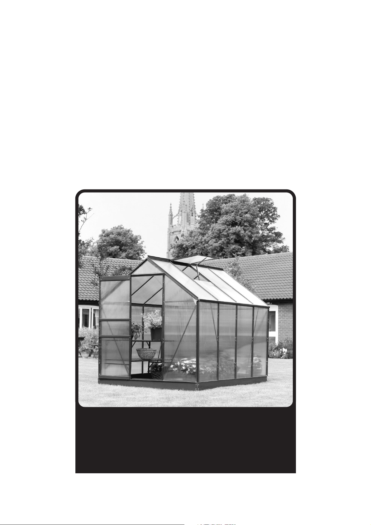
Greenhouse
Assembly Instructions
Greenhouse
Assembly Instructions
For sizes:
8ft x 6ft (2.57m x 1.93m)
6ft x 6ft (1.93m x 1.93m)
4ft x 6ft (1.31m x 1.93m)
Page 2
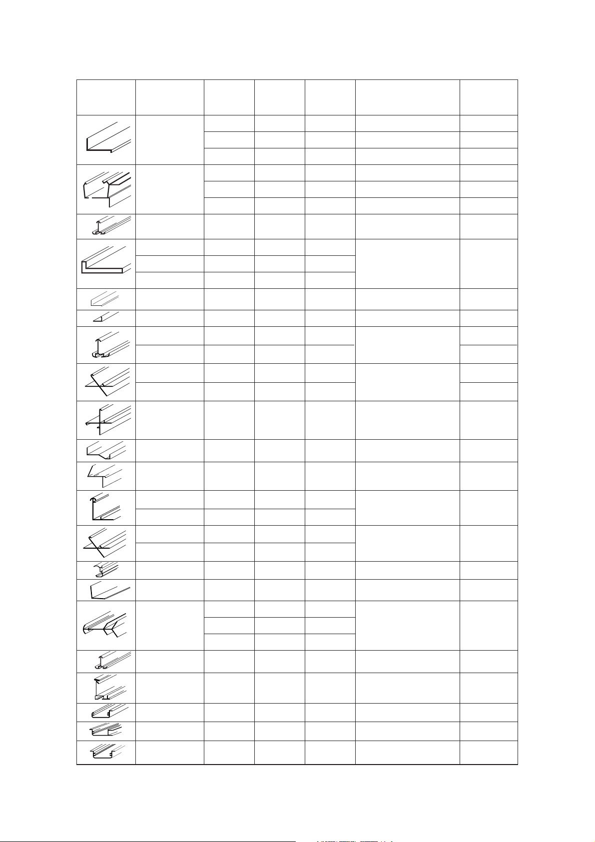
Frames
Position
(viewed 4x6 6x6 8x6
Profile from inside) House House House Description Code
2 side - lower horizontals (4ft) A1-4
Bottom bars 2 side - lower horizontals (6ft) A1-6
2 side - lower horizontals (8ft) A1-8
2 side - upper horizontals (4ft) A2-4
Gutter bars 2 side - upper horizontals (6ft) A2-6
2 side - upper horizontals (8ft) A2-8
Verticals 2 4 6 side glazing uprights A3
Sides 2 4 4
Back 2 2 2 Diagonal braces - multi use G1
Front 2 2 2
Bottom bar 1 1 1 Back - lower horizontal B1
Mid height 1 1 1 Back - horizontal brace B2
Back Left 1 1 1
Back
B3-1
Back Right 1 1 1
glazing verticals
B3-2
Back Left 1 1 1
Roof
B4-1
Back Right 1 1 1
edge bars
B4-2
Back 2 2 2
Corner verticals H1
Front 2 2 2
Base bar 1 1 1 Front - lower horizontal C1
Door frame top 1 1 1 Door frame horizontal C2
Left 1 1 1 Front uprights C3-1
Right 1 1 1 (Door Jams) C3-2
Front left 1 1 1 Roof edge C4-1
Front right 1 1 1 Beams C4-2
Door frame top 1 1 1 Door runner C5
Mid height 2 2 2 Front horizontal braces C6
1 D1-4
Roof apex 1 Ridge bar D1-6
1 D1-8
Roof sides 2 4 6 Roof glazing bar D3
Door sides 2 2 2 Door verticals E1
Door top 1 1 1 Door - upper horizontal E2
Door bottom 1 1 1 Door - lower horizontal E3
Door middle bars 2 2 2 Door - mid horizontal E4
Page 3
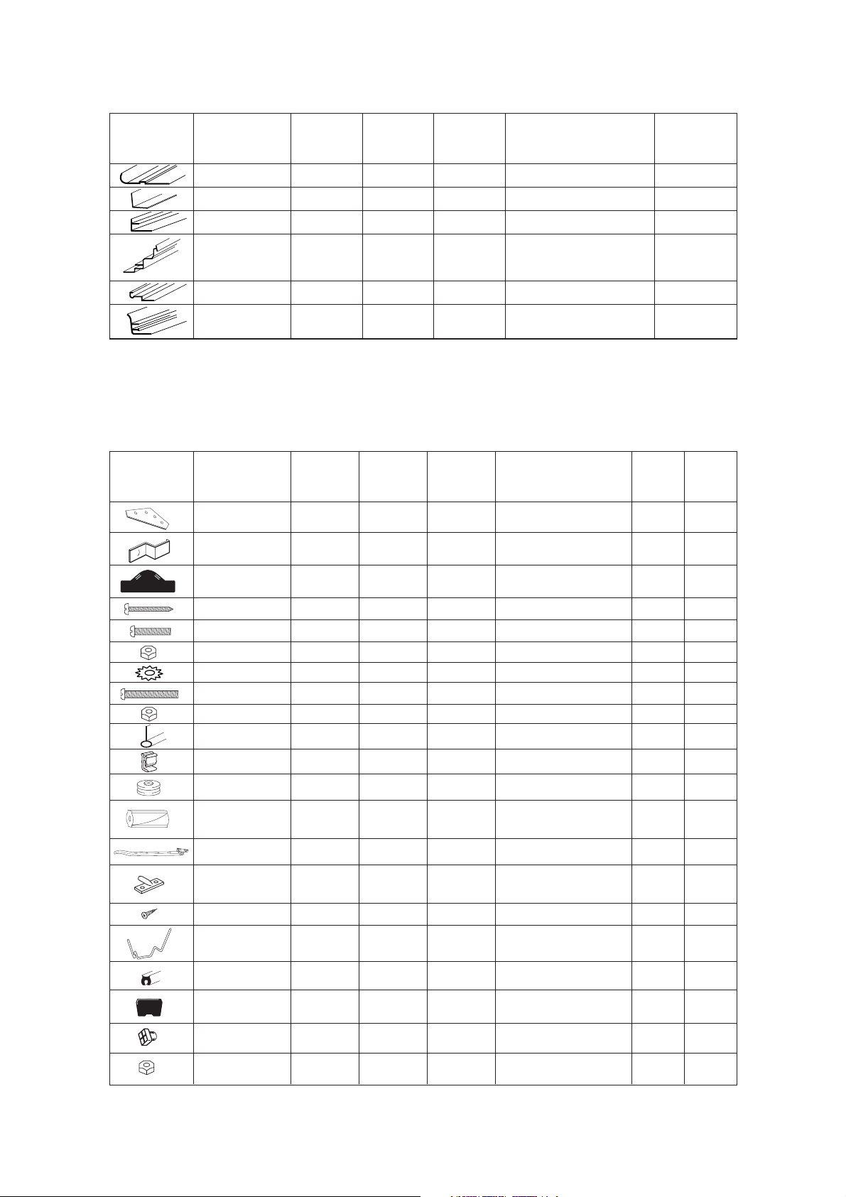
Frames (continued)
Components
Position
(viewed 4x6 6x6 8x6
Profile from inside) House House House Description Code
Door top bar 1 1 1 Door runner housing E5
Front corner 1 1 1 Door runner support arm E6
Between roof bars 0 1 1 Vent mounting bar F1
Window top 0 1 1 Vent top bar F2
Window front 0 1 1 Vent bottom bar F3
Window sides 0 2 2 Vent side bars F4
Position
(viewed 4x6 6x6 8x6 Size
Profile from inside) House House House Description (mm) Code
Upper corners
inside 4 4 4 Corner plate G2
Door frame
top corners 2 2 2 Door runner mount 15 E9
Ends of CV’s
and RG’s 8 8 8 Profile end caps G3
Door horizontals 16 16 16 Door screws No 6x19 619
Runner wheels 2 2 2 Door runner bolts M4x16 M416
222 Nut for M4 M4 M4-1
222Washer for M4 M4 M4-2
DRS to spacer 1 1 1 Door spacer bolt M6x40 M640
111 Nuts for M6 M6 M6-1
Inside door frame 2 2 2 Door seal 1610 E10
Door bottom 2 2 2 Door base sliders E11
Door top 2 2 2 Door running wheel E12
Free end of
Door runner 1 1 1 Door gear spacer E13
Vent bottom bar 0 1 1 Vent stay F10
Vent horizontal
Mount 0 2 2 Vent catch F12
066Vent catch screws No6x6 66
Clips into glazing
bars 144 172 204 Glazing spring clip G4
All glazing bars 45m 54m 64m Rubber glazing bead G5
444Gutter end caps A20
74 94 102 Bolts M6x10 M610
74 94 102 Nuts for M6 M6 M6-1
Page 4
Introduction
Safety
Precautions when assembling a greenhouse:
The wearing of protective gloves and stout footwear is essential when handling glass and recommended even for
Polycarbonate which does not shatter but has sharp edges.
Protective goggles are recommended whilst handling glass and the glazing spring clips.
Assembly of the greenhouse frame is much easier with two people and essential for glazing with glass.
Site selection:
Choose a site in maximum light, ideally with no direct shade.
Avoid overhanging trees as much as possible as leaves will make regular cleaning necessary and broken branches are a
potential hazard.
Small trees, bushes or fences nearby can be helpful, acting as a wind break.
A position close to the house will make access easier for watering and tending and also make it easier to supply
power cables or automatic watering systems if required.
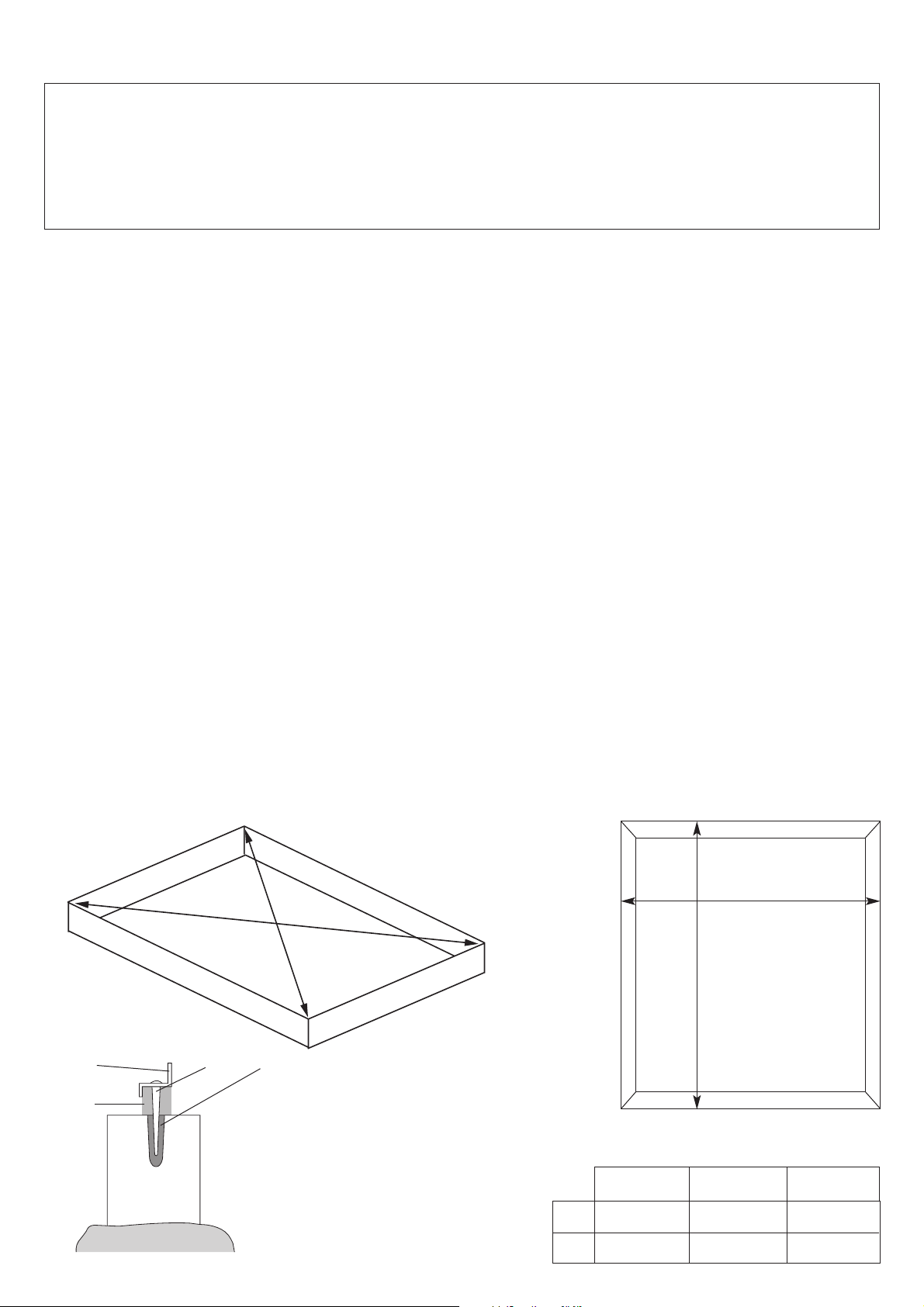
Site selection & preparation:
The site must be prepared so that the base of the greenhouse is level all round and checking with a spirit level is
required.
Base options & construction:
The use of purpose-made, galvanised steel bases is recommended.
They are made to fit the greenhouses.
It is easier to maintain a level and square foundation.
They are easy to install, requiring little expertise: full instructions are included in the pack.
Bases can also be constructed from bricks, blocks, or mounted on a concrete pad.
The bricks or blocks should be cemented onto firm and level concrete footings and the greenhouse frame drilled and
screwed to the base. Fig3.
If a concrete pad is made, it is important that this slopes towards the edges to prevent water ingress.
Time must be allowed for any concrete or cement to dry before mounting the greenhouse.
The base must be square or the greenhouse will be distorted. Fig1 & Fig2.
The greenhouse must be firmly fixed to the ground: the base should be constructed and installed before the
greenhouse assembly is undertaken.
A
A
A = A
When the diagonal
measurements are equal,
the base will be square.
X
Y
Y
X
4 x 6
1920mm
1298mm
1920mm
1920mm
1920mm
2542mm
6 x 6 8 x 6
Screw & Plug
Greenhouse
Frame
Batten
Brick base
Concrete pad
Fig1
Fig2
Fig3
Page 5

Before you start:
IMPORTANT: Read the instructions completely before starting assembly.
• Construct the base first so that the greenhouse can be securely mounted when completed.
• Find someone to help you: it is much easier with someone to hold parts, pass tools etc. This is not very heavy
work so would suit most able-bodied people.
• Allow plenty of time:
rushing often causes errors and the re-doing of incorrect assemblies. If you have never built a
greenhouse before, it can take most of a day to carefully complete the construction.
• Have the right tools to hand:
•Cross head and flat head screwdrivers: electric ones save some elbow grease!
•10mm Spanner: a ratchet socket set is ideal or, even better, a 10mm socket that fits an electric drill or screwdriver.
•Safety clothing as recommended in the ‘Safety’ section.
• Lay out the parts by greenhouse section,
ideally around the base as shown, and check that all are present before
commencing construction. Lay on cloths or plastic sheets if there is any risk of scratching the parts.
• F
ollow the constr
uction sequence.
•Side sections
•Back section
•Front section
•Frame assembly and roof
•Door
•Vent (if applicable)
•Glazing
• All illustrations are based on viewing the parts from the inside of the greenhouse, except where stated.
• Assemble the greenhouse loosely where possible and tighten when all in place so that minor adjustments can be
made. Note that some nuts will need to be tightened to keep them in place.
• Tighten all nuts carefully, being sure not to miss any. Check the frame is square and using a spirit level to check
that it is upright.
Roof Section (D)
Side Section (A)
Back Section (B)
Side Section (A)
Vent Section (F)
Door Section (E)
Base
Front Section (C)
Page 6

A Gr
eenhouse Sides
4 x 6 6 x 6 8 x 6
A1 and A2 are coded
by Greenhouse size.
e.g. :-
(A1–4 = 4 x 6)
(A1–6 = 6 x 6)
(A1–8 = 8 x 6)
A3
A2
A1
G1
Introduction
Lay parts on the
ground, as pictured at
the top of this page.
Assemble loosely
with the nuts to the
inside of the
structure.
Step
Insert bolt into the
channel in the
upright (A3).
Bolt glazing uprights
to the outside of the
bottom bar.
Step
Bolt diagonal braces
to inside of bottom
bar.
Note: the flat side of
the bottom bar faces
inwards.
Step
Before bolting the
glazing uprights to
the outside of the
top gutter bar, insert
bolts into the
channels for fixing
the diagonal braces.
Step
Use the inserted
bolts (see 3) to
secure the diagonal
braces to the
uprights. Do not
tighten yet.
Step
Bolt the diagonal
brace to the inside of
the top gutter bar.
Repeat for the other
side of the
Greenhouse.
Profile Code 4x6 6x6 8x6
A1
A2
A3
G1
M610
M6-1
2
2
2
2
Used for all sections so quantity not
listed in this or other parts lists.
2
2
4
4
2
2
6
4
A1
A3
A1
G1
A2
A3
A3
G1
A2
G1
Note: Although there are different greenhouse
sizes, the steps are the same.
Pictures viewed from inside the Greenhouse except where stated
5
3
3
3
5
4
4
1
1
2
2
1
1
2
3
4
5
Page 7

This section is the
same for 8x6, 6x6
and 4x6
greenhouses.
Lay the parts on the
ground as pictured and
assemble loosely. Check
that the corner verticals,
glazing uprights and the
roof bars are in the
correct positions (left
and right sides are
different).
Step
Corner joint assembly:
bolt the corner plates
to the inside of the
roof and vertical bars.
Bolt the horizontal and
diagonal braces inside
the corner plates.
Step
Bolt bottom bars to
corner and glazing
verticals.
Note: the flat side of
the bottom bar faces
inwards.
Step
Before bolting the
glazing uprights to the
outside of the roof
bars, insert bolt into
the channel for fixing
the horizontal brace.
Step
Bolt the diagonal
braces to the inside of
the bottom bars.
Step
Bolt the horizontal
braces to the inside of
the glazing uprights
using the bolts inserted.
See step
Profile Code 4x6 6x6 8x6
B1
B2
B3-1
B3-2
1
1
1
1
1
1
1
1
1
1
1
1
B4-1 1 1 1
B4-2 1 1 1
H1 222
G1
G2
222
222
B Gr
eenhouse Back
B3-1 B3-2
H1
G1
G1
H1
Pictures viewed from inside the Greenhouse except where stated
B2
B1
B4-2
B4-1
B4
B2
H1
G1
G2
B3-1
& B3-2
1
1
4
4
6 6
2
5
2
3 5
&
1
2
3&
4
5
6
M610
M6-1
Used for all sections so quantity not
listed in this or other parts lists.
4
3
&
Page 8

This section is the same for 8x6, 6x6 and 4x6
greenhouses.
Lay the parts on the ground as pictured and assemble
loosely.
Check that the corner verticals and the roof bars are in
the correct positions (left and right).
Assemble front end section in the same sequence as the
back section, but note that: a) horizontal brace is in
two sections b) door uprights replace the glazing
uprights.
Step
Bolt the two middle
horizontal braces to the
inside of the door
uprights.
Step
Note that the diagonal
braces fit the same hole
as the door uprights.
Step
Bolt the door frame top
bar to the outside of the
roof bars, left and right.
Step
Insert bolts from the
outside through the door
frame top bar and
through the support clips
(E9) and attach nut
loosely. Hook support
clips into groove in the
door upright.
H1
G2
C Gr
eenhouse Front
C1
C2
C3-1 C3-2
H1 G1
G1
H1
C6 C6
C4-1
C4-2
C5
C6
C3-1
C1
C4-2
C2
C3-2
C2
E9
C3-2
C5
C2
Outside view
3
4
1
1
2 2
1
2
3
4
6
&
3
4
5
&
C4-2 1 1 1
Profile Code 4x6 6x6 8x6
C1
C2
C3-1
C3-2
C4-1
1
1
1
1
1
1
1
1
1
1
1
1
1
1
1
C5 111
C6 222
G1 222
222
222
222
M610
M6-1
Used for all sections so quantity not
listed in this or other parts lists.
E6 1 1 1
M640
111
E13
111
E9
Fit the support arm E6 as
shown. Use a bolt
inserted into C5 at the
top and bolt M640 and
spacer E13 at the
bottom.
E13
E6
C5
M640
Outside view
Pictures viewed from inside the Greenhouse except where stated
Step Slide the door
runner bar over the bolt
heads and into position
with the right hand edge
flush with the door
frame. Tighten nuts.
Step Insert nut and
bolt into the end hole of
the door runner bar to
act as a door stop.
5
6
E6
Page 9

Step
In this section, the four
greenhouse walls are joined
together and the roof
added. This phase is best
undertaken by two people.
Fit the profile end caps to
the roof and upright bars
before assembly.
Step
Bolt the bottom side and
front bars to the inside of
the corner post.
Step
Bolt the gutter side bar
to the inside of the
corner section.
Repeat 2 and 3 for all
four corners.
Step
Bolt the ridge bar to the
underside of the end roof
bars as shown.
Step
Bolt the roof glazing bars
to the ridge and gutter
bars, remembering to
insert a pair of bolts into
the channels where the
vent is to be fitted (8x6
and 6x6 houses only).
Lift the frame onto the
prepared base and fix
loosely. Check that the
frame is square and sits
nicely on the base before
tightening all nuts.
Profile Code 4x6 6x6 8x6
D1
D3
G3
1
2
8
1
4
8
1
6
8
D Gr
eenhouse Assembly
& R
oof Section
D3
D1
(D1–4 = 4 x 6)
(D1–6 = 6 x 6)
(D1–8 = 8 x 6)
Pictures viewed from inside the Greenhouse except where stated
Outside view
D1
C4
1
3
&
2
4
4
5
1
2
3
4
5
M610
M6-1
Used for all sections so quantity not
listed in this or other parts lists.
Page 10

This section is the same for all
greenhouse sizes in the range.
Lay the parts on the ground as
pictured and assemble loosely.
Step
Push the plastic door base
sliders into the door bottom
bar as shown.
Screw through the uprights into
the bottom bar and the slider.
Step
Screw through the uprights into
the door middle bars and top
bar.
Fix the door running wheels
to the runner housing as
shown and bolt the housing
to the door top rail.
Insert the door seal into the
door uprights and trim to
length.
Note: Stretching can occur
whilst fitting. Allow a few
minutes to shrink back
before trimming.
Ease the door base slider
onto the bottom track.
Slide the running wheels
onto the top track.
Adjust the wheel housing for
smooth running of the door.
E Gr
eenhouse Door Assembly
E2
E4
E4
E5
E3
Door Assembly Parts
Outside view
E1
E11
E3
E1
E4
E1
E2
E5
Pictures viewed from inside the Greenhouse except where stated
E1
E1
E2
E5
2 2
3
3
2 2
1
1
1
&
E5 111
Profile Code 4x6 6x6 8x6
E1
E2
E3
E4
2
1
1
2
2
1
1
2
2
1
1
2
619 16 16 16
M416
M4-1
M4-2
E10
222
222
222
M6-1
111
222
E11
222
E12
222
M610
M6-1
Used for all sections so quantity not
listed in this or other parts lists.
2
3
Page 11

Step
Bolt the vent side bars
loosely to the vent top bar
as shown.
Step
Fit nuts and bolts to the
bottom ends of the vent
sides but do not tighten.
Slide the glazing sheet into
place.
Add the vent bottom bar as
shown. Check that the vent
is square and tighten all
nuts.
Slide completed vent along
the ridge bar until in
position.
Bolt the vent mounting bar
onto the roof bars using the
bolts previously inserted
(section D, step 5).
Adjust to butt up to the
vent and tighten.
Screw vent stay to vent
bottom bar using the pre-
drilled holes.
Screw the vent stay catches
to the vent mounting bar
using the pre-drilled holes.
F Gr
eenhouse Vent Assembly
(Not applicable to the 4x6 Greenhouse)
F2
F3
F4
F4
Pictures viewed from inside the Greenhouse except where stated
Notes:
• The assembly is slightly different for glass and
• polycarbonate glazing.
• Glazing sheets are from separate glazing packs.
Glass
D1
F1
D3
F3
F10
F12
1
2
1
2
1
2
Profile Code 4x6 6x6 8x6
F1
F2
F3
F4
0
0
0
0
1
1
1
2
1
1
1
2
F10 0 1 1
F12 0 2 2
66 066
Poly
Outside view
M610
M6-1
Used for all sections so quantity not
listed in this or other parts lists.
Outside view
↔
Page 12

A20 Gutter End Cap
Glazing
Accessories
NOTE: Glazing instructions are included in the glazing pack.
You can enhance your greenhouse with a number of accessories from the range.
These include:
• 1 Tier Staging
• 2 Tier Staging
• Fold-away Staging
• Fold-away Shelf
• Auto Vent
• Louvre Vent
• Rainwater Kit
Customer Services: In case of difficulties please ring 01406 372227
Glazing Bead G5 must be
applied to all glazing bars
prior to glazing with
polycarbonate or glass.
Fit to bars as shown and
trim to length.
Note: Stretching can
occur when fitting. Allow
a few minutes to shrink
back before trimming.
Fit gutter end caps A20
as shown.
G5 Glazing Bead
Profile Code 4x6 6x6 8x6
G5
A20
1
4
1
4
1
4
 Loading...