

GARDINER TECHNOLOGY GARDTEC SPEECH DIALLER Installation & Programming Instructions

SS
SS
HH
TTTTHH
PP
PP
EE
EE
EE
EE
EE
Installation
Programming
Instructions
EE
GG
CC
CC
GG
HH
HH
AA
AA
&
RR
RR
DDIIII
DD
DDTTTT
DD
AALLLLLLLL
AA
EE
EE
CC
CC
EE
EE
RR
RR


Contents
Introduction...................................................................................1.0
Telephone Line Requirements .....................................................1.1
Approval .......................................................................................1.2
Dialler Fixing.................................................................................2.0
Telephone Line Connection..........................................................3.0
Connection to Gardtec
Connection to Gardtec
Connection to Other Equipment...................................................3.2
Terminal Descriptions...................................................................4.0
Programmable User Options........................................................5.0
Programmable Engineer Options.................................................5.1
Special Features...........................................................................5.2
Initial Power Up ............................................................................6.0
Programming................................................................................7.0
Telephone Numbers.............................................7.1
Messages.............................................................7.2
User Code ............................................................7.3
Dial Attempts........................................................7.4
Call Acknowledge.................................................7.5
Engineer Code......................................................7.7
Trigger Modes ......................................................7.8
Line Fault Monitor.................................................7.9
Multi-Trigger Inhibit...............................................7.10
Serial Comms.......................................................7.11
FTC (FS)...............................................................7.12
800 Series
580
...............................................3.1
(via interface)...................................3.1
Using the Dialler...........................................................................8.0
Aborting Calls...............................................................................8.1
Viewing Last Call Log...................................................................8.2
Error Messages............................................................................9.0
Guardian Guide............................................................................10.0
Engineers Appendix 1 (Default Settings)......................................11.0
Engineers Appendix 2 (Reset Modes)..........................................11.1

1.0 INTRODUCTION
The Gardiner Technology Gardtec Speech Dialler is intended for use as an automatic
message dialler. The primary use for the dialler is for connection to an alarm system
although the unit is flexible enough to have many other uses where the need for automatic
messages exists.
The dialler is fully programmable via an engineer code with limited programmable options
available to the user via a user code. Once programmed the unit will retain all
programmed settings (including speech), even in the event of a complete power down.
Up to four telephone numbers may be programmed into the dialler and call
acknowledgment may be programmed on or off
The unit may be used with the Gardtec 800 Series of control panels (or Gardtec 580 via an
interface) as a plug on unit, or hardwired to any other control panel that offers suitable
outputs.
The dialler offers one common message (11 seconds duration) and up to three shorter
messages (3 seconds duration each).
When connected to the Gardtec 800 Series or the Gardtec 580 (with interface) the dialler
is powered and activated via the serial communications link to the control panel. If
connected to other control equipment the dialler should be given a 12V d.c supply and is
triggered via three start input terminals, the start polarity of these terminals is fully
programmable.
Once triggered the dialler will dial the first telephone number, when the call is answered
the common message will be played followed by one of the three short messages
corresponding to alarm channels 1, 2 and 3 on the Gardtec (or inputs 1, 2 or 3 if controlled
by other equipment). If acknowledge is programmed off the dialler will terminate the call
after passing the message to the first telephone number , if no answer is obtained from
telephone number 1 the unit will sequentially move on to the next telephone numbers until
it is successful.
If acknowledge is programmed to on, the unit will dial the telephone numbers in the same
way but the calls will require acknowledgement by the call recipient. The number of
acknowledged calls require to terminate the dialling sequence is fully programmable by the
user.

1.1 TELEPHONE LINE REQUIREMENTS
Before specifying the Gardtec Speech Dialler you should check that the following
criteria can be met.
a) That the line can support DTMF dialling (Tone dialling)
b) That the dialler will not be connected to a 1+1 carrier system.
c) That the dialler will not be connected as an extension to a PABX.
d) That no other digital equipment will be used on the line (Fax etc).
The plug-on connector for the Gardtec 800 (or 580 with interface) or TB3 must connect
with ports of other equipment eligible for the general approval NS/G/1234/J/00003 or
otherwise approved for use with the Telephone Network.
It is essential that interconnection circuits should be such that the equipment continues to
comply with the requirements of 4.2 of EN41003 for TNV (Telephone Network Voltage)
circuits and 2.3 of EN60950 for SELV (Safety Extra Low Voltage) circuits after making
connections between circuits.
1.2 APPROVAL
This apparatus has been approved for the use of the following facilities:
a) Auto-Calling
b) MF Tone Dialling
Any other usage will invalidate the approval of the apparatus if as a result it then ceases to
comply with the standards which approval was granted.
Product Name: Gardtec Speech Dialler
BABT Approval Number: 503519
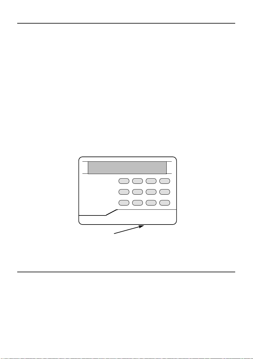
2.0 DIALLER FIXING
12345678NO90
YES
Disconnect from BT line before removing cover(s)
Remove the flap securing screw on the lower edge of the remote keypad casing (see
Fig1.) and unclip the flap by moving outward and downward in one movement. The area
behind this panel is a restricted access/service area and is intended to be used only
by the installer.
Unclip the two cover retaining clips (situated at either side towards the bottom of the unit)
and carefully lift forwards and upwards in one motion. Note the front cover and the P.C.B
are one assembly.
Mark and drill the wall and fit suitable wall plugs. Feed the cable through a suitable entry in
the backplate and fix the backplate to the wall using 3 x No.6 screws at least 30mm long.
Carefully hook the front cover onto the backplate at the top edge and, with the cable
through the aperture in the front cover, snap the cover into place.After wiring has been
completed replace the front flap and the flap fixing screw.
Fig 1.
Cover fixing screw
3.0 TELEPHONE LINE CONNECTION
The unit is supplied pre-wired with a 3m length of telecom cable that is terminated with a
standard BT type plug. If this is to be connected to a socket that is already in use or the
cable not long enough an approved splitter or cable extension should be used.
The dialler has a REN1 rating, the maximum number of RENs that may be connected to
the Telephone Network is 4. Each piece of approved equipment that is connected will
state what REN rating it has, you should add together the RENs of all telephone
equipment that you have connected, this total must not exceed 4.
3.1 CONNECTION TO GARDTEC
12345678NO90
YES
800 Series & 580
Connection to the Gardtec
800 Series
(or Gardtec
580
via interface) is via the Speech
Dialler Serial Lead Part No 04-070. The plug end of the lead should be connected to the
Gardtec
800 Series
SK3 (Digigard Communicator) (or PLG1 on the
580
interface) the
flying end should be connected to the dialler as shown below.
Dialler Flying Lead Function
Terminal Core Colour Panel to Dialler
FLT Yellow DIN to DOUT
TRG1 Green DOUT to DIN
TRG2 Black CLOCK
0V Blue 0V
12V Red 12V
800
Program Gardtec
Program Gardtec
When the Speech Dialler is connected to the Gardtec
Digicom Type option to Digigard.
800
PA Mode to Bells Always or Silent
800
Alarm activation will trigger
message 3, PA activation will trigger message 2 and channel 1 activation (as
programmed) will trigger message 1.
The link between 12V and Line fault on the Gardtec
800
must be removed.
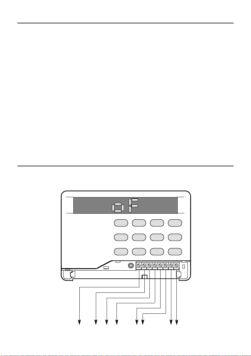
3.2 CONNECTION TO OTHER EQUIPMENT
The dialler may be connected to any equipment that is able to give a positive or negative
output examples of this are given in Figs 2 to 5.
Fig 2.
To L/F
Input
Fire PA Alarm
Control Panel Outputs
FLT TRG1 TRG2 TRG3 TMP TMP 0V 12V
To Control
Panel
Tamper Loop
To Control
Panel 12V
Aux Supply
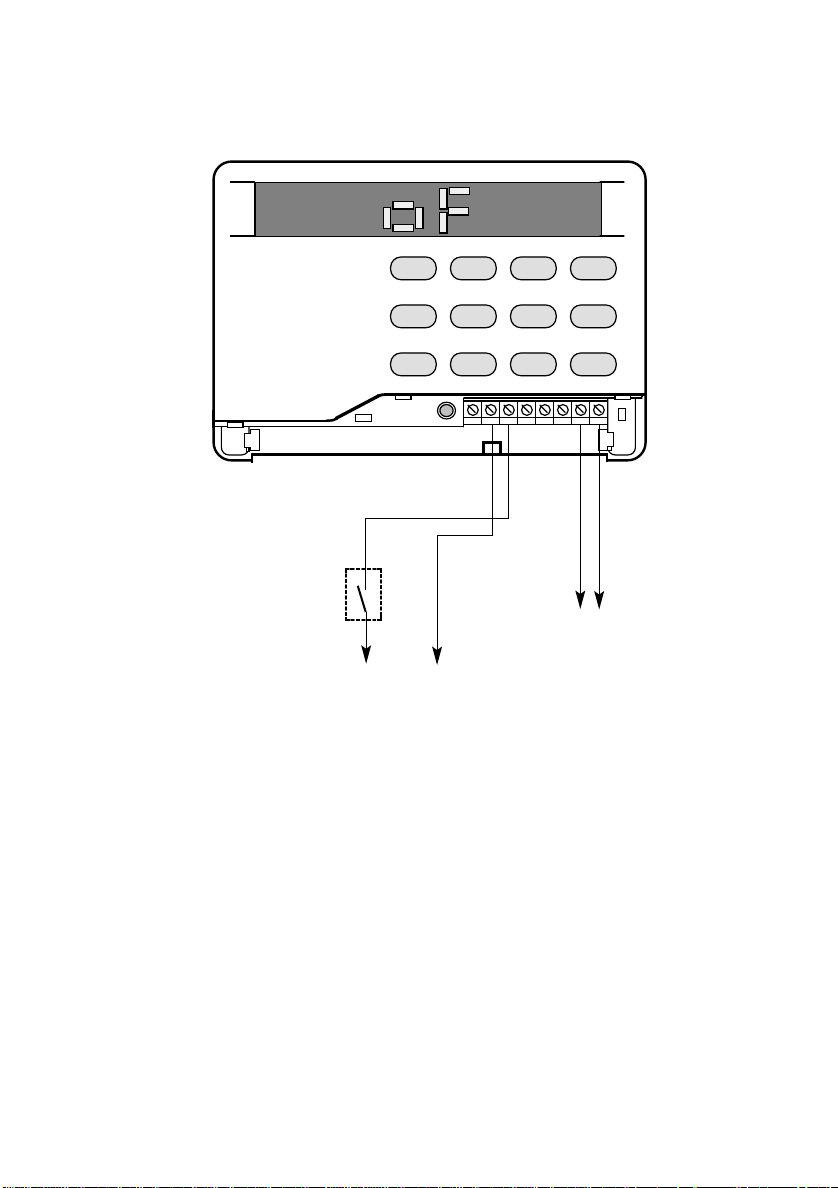
Fig 3. Typical connection for PA and Fire without connection to an alarm control panel.
12345678NO90
YES
FLT TRG1 TRG2 TRG3 TMP TMP 0V 12V
N/O PA
Button
0V 12V
To 12V Power Supply
To Power
Supply
Negative
Trigger From
0V
Smoke
Detector
Note: Unit should be programmed for negative start.
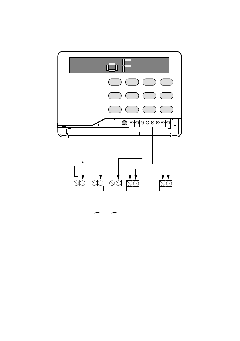
Fig 4. Typical connection to Gardtec
12345678NO90
YES
PA and Alarm. Note the use of a 6K8 pull-up resistor across bell terminals.
6K8
350/350+ (and 580 without interface)
FLT TRG1 TRG2 TRG3 TMP TMP 0V 12V
giving Fire,
+ -
BELL
+ -
N/C FIRE LOOP
Program Trigger Mode to Control Panel Trigger
Program Multi Trigger Inhibit to ON
AZx
+ -
AZx
N/C PA LOOP
+ TAMP
+ -
AUX

4.0 TERMINAL DESCRIPTIONS
FLT TB3 (SELV)
This is the fault output and will change state when there is a failure to communicate, a cut
telephone line or the supply voltage to the unit falls below 9.5V. The output is open
collector held high through a 47K resistor. The output is normally high going low on fault.
The FLT terminal also doubles as Data OUT when the dialler is connected to a Gardtec
800 Series
TRG1 TRG2 TRG3 TB3 (SELV)
These are the start input terminals, when triggered the dialler will dial out and when
answered will pass the common message followed by the message number corresponding
to the trigger terminal, e.g when TRG3 is triggered and the call is answered the common
message will be played followed by message No 3.
The start polarity of the trigger terminals is programmable to +Ve or -Ve.
Recommended use of the trigger terminals would be as follows:TRG1 = Common + Message1 Fire message
TRG2 = Common + Message 2 PA Message
TRG 3= Common + Message 3 Intruder Message
or Gardtec
580
(via interface) by the serial lead (supplied with the dialler).
TMP TB3 (SELV)
Two TMP terminals are provided. These terminals are connected to the cover flap tamper
switch of the dialler and may be connected to the tamper circuit of the control equipment (if
applicable).
0V & 12V TB3 (SELV)
Power supply connection terminals. Voltage applied to these terminals may be in the
range 10 - 15V d.c it should be noted that a fault condition will be generated to both the
fault output and communication port if this voltage falls below 9.5V. This condition will be
restored when the voltage rises above 10.7V
TELEPHONE LINE CONNECTION A & B (TNV)
Factory connected to 3m BT lead.

5.0 PROGRAMMABLE USER OPTIONS
The dialler is fully programmable, all settings will be retained in the event of the dialler
being down powered. A description of each option is given below:-
Emergency services must not be called with this equipment.
Repeat numbers will not be accepted by the dialler.
Telephone No 1
Any sequence of digits (Max fifteen digits).
Telephone No 2
Any sequence of digits (Max fifteen digits).
Telephone No 3
Any sequence of digits (Max fifteen digits).
Telephone No 4
Any sequence of digits (Max fifteen digits).
The user shall ensure all numbers are correctly entered.
Speech Messages
Common message
When the dialler is triggered and the call is answered the dialler will pass this common
message followed by the short message corresponding to the trigger input. Speech for this
common message may be up to 11 seconds duration, a typical message would be:-
"This is John Atherton 5 High Street Newtown, this is a...."
Short Message 1
This message corresponds to a trigger 1 input and will be played after the common
message. Speech for short message 1 may be up to 3 seconds duration, a typical
message would be:-
"Fire Alarm"
Short Message 2
This message corresponds to a trigger 2 input and will be played after the common
message. Speech for short message 2 may be up to 3 seconds duration, a typical
message would be:-
"Personal Attack"

Short Message 3
This message corresponds to a trigger 3 input and will be played after the common
message. Speech for short message 3 may be up to 3 seconds duration, a typical
message would be:-
"Burglar Alarm"
Once the speech message(s) have been programmed they may be replayed with or
without the preceding common message
User Options
Change User Code
The user has the option (via the existing user code) to change the user code to any other
four digit number. should the new user code be the same as the engineer code the dialler
will display 'no' and the code will not be updated. The default user code is 5678
Change Dial Attempts
The dialler has a list of up to four telephone numbers, the number of dial attempts is the
number of times it will try to dial these numbers. A successful call will be registered when
the message is passed to the recipient (and acknowledged if required).
This option allows the number of times the dialler will dial the telephone numbers on the
list to be programmed from 1 to 3 times.
Call Acknowledge
Call acknowledge may be programmed to 0, 1, 2, 3 or 4. If 0 is programmed the dialler will
see when it has passed a message to the recipient and the dialler will then shut down. If
programmed to 1, 2, 3 or 4 the dialler will give a tone after the message has been passed,
this tone then has to be acknowledged by the recipient by pressing the # key for 1 second,
the tone will be repeated and will need to be acknowledged again by pressing the # key. If
the acknowledgement is accepted a triple tone will be given and the call will be registered
as successful by the dialler.
This procedure will then be repeated to the other telephone numbers until the desired
number of acknowledgments has been received. The default number of acknowledgments
required is 1.
It is advisable that the total of telephone numbers you have programmed should be at
least equal to the number of acknowledgments programmed.
View Last Call Log
This option allows the user to view the last call log. The log will give information as to the
last telephone number dialled and what message was passed. Information is also stored
concerning failure to communicate and aborted calls. The log is accessed by pressing the
NO key when 'on' or 'oF' is displayed.
 Loading...