

Page 1
INSTRUCTIONS
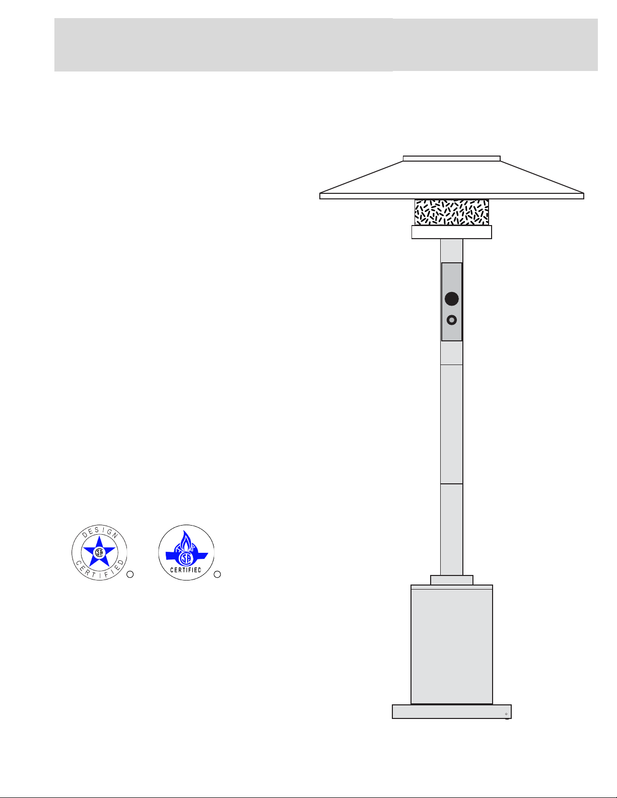
COMMERCIAL
OUTDOOR
HEATER
Model NO.:
HS-PC/GH/SH/SS
RR
1
Page 2
Assembly, Installation & Instruction Manual
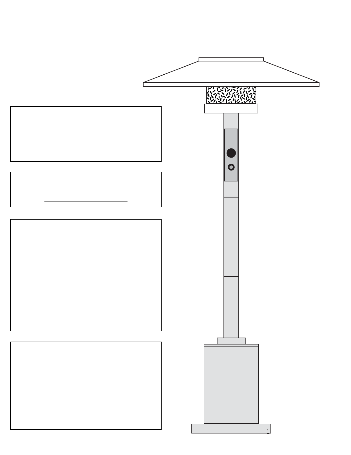
COMMERCIAL
OUTDOOR HEATER
FOR YOUR SAFETY:
DO NOT STORE OR USE GASOLINE
OR OTHER FLAMMABLE VAPORS
AND LIQUIDS IN THE VICINITY OF
THIS OR ANY OTHER APPLIANCE
WARNING:
THIS APPLIANCE IS DESIGNED FOR
OUTDOOR USE ONLY
WARNING:
IMPROPER INSTALLATION,
ADJUSTMENT, ALTERATION,
SERVICE, OR MAINTENANCE CAN
CAUSE INJURY OR PROPERTY
DAMAGE. READ THE ASSEMBLY,
INSTALLATION, OPERATING, AND
MAINTENANCE INSTRUCTIONS AND
ALL WARNINGS THOROUGHLY
BEFORE INSTALLING OR SERVICING
THIS EQUIPMENT
FOR YOUR SAFETY:
IF YOU SMELL GAS:
1. SHUT OFF GAS TO THE
APPLIANCE
2. EXTINGUISH ANY OPEN FLAME
3. IF ODOR CONTINUES,
IMMEDIATELY CALL YOUR GAS
SUPPLIER
2
Page 3

Things to know about your 38,000 BTU
Commerical Outdoor Heater
Radiant Heat at 38,000 BTU’s:
The Commerical Outdoor Heater generates “Radiant Heat.” Unlike forced-
air heat which goes up, radiant heat, like light waves reflects off of objects,
warming the surface of the objects. This kind of heat is undisturbed by wind
and ambient air temperatures.. Like light, radiant heat moves in waves.
People absorb these waves creating a warming sensation on your skin and
other surface objects. The more intense the BTU’s, the closer the radiant
heat waves are, the more individuals will feel a warming sensation. The
ambient temperature around the heater is equal to 38,000 BTU’s after burning
for five minutes. The Commerical Outdoor Heater features an adjustable
control valve, allowing for a desired heat output. Whether a cozy dinner on
the patio or those large gathering, you’ll always have the right heat.
Burner Characteristics:
The Commerical Outdoor Heater burns with a blue flame being 2”-3” and
a yellow/orange tip. The emitter will glow a hot red, radiating heat to the
hood and down with warmth for you.
Safety Tilt Feature:
The Commerical Outdoor Heaters come with a Safety Tilt feature that will
shut off the gas if the heater tilts over or is knocked down. This unique
safety feature is just another comfort for your peace of mind.
3
Page 4

Care of L.P. (Propane) Gas Cylinders
(Not included)
WARNING:
L.P. GAS CANNOT AND SHOULD NOT BE USED ON UNITS
EQUIPPED FOR NATURAL GAS.
If your heater is designed for use with an L.P. cylinder (not included), the cylinder must meet the following
requirements:
• Cylinder weight is 20 lb. (9.07 kg); cylinder has outside diameter of 12-1/8 in. (30.8 cm), length of
18 in. (45.7 cm) and is constructed and marked to specifications of the U.S. Department of
Transportation (D.O.T.) or Canadian Transport Commission (C.T.C.). Cylinder has shut-off valve outlet
which is a No. 510, female P.O.L.; a safety relief device which has direct communication with vapor space
of cylinder. Supply system is arranged for vapor withdrawal. Cylinder includes a collar to protect valve.
When use with L.P. gas, special precautions should be observed when handling L.P. cylinders. Remember
that this is gas and under pressure, which MUST be handled with care. Ask your L.P. gas dealer to give
you a “short course” on necessary safety precautions and check local codes for use, storage and transport
regulations. Among the recommended practices are:
1. Always keep L.P. cylinders upright.
2. Do not subject L.P. cylinders to excessive heat.
3. Avoid damage to tank valves - handle them with care.
4. Never store L.P. cylinders indoors or in direct sunlight.
5. Do not handle L.P. cylinders roughly.
Follow instructions for connecting and disconnecting L.P. cylinders for the heater and be sure to leak check
all connections each time the cylinder is connected. Always use a solution of soap and water.
NEVER USE AN OPEN FLAME!
Always turn off the gas supply to the heater at the cylinder as soon as you are finished using the heater.
The L.P. cylinder must be equipped with the pressure regulator and hose assembly supplied with the
heater. The pressure regulator is set at the factory for maximum efficiency.
Visually inspect the entire length of the hose for damage before use. This requires opening the door of the
L.P. cylinder enclosure. If damage or excessive wear is found, replace the regulator assembly immediately.
If needed, order only factory original parts. Do not attempt to substitute parts.
Always store L.P. Cylinders in a well ventilated space. If you intend to store the heater indoors, disconnect
the L.P. Cylinder and store it outside. Disconnected cylinders must have a threaded valve plug tightly
installed. When the L.P. Cylinder is not disconnected from the heater, the heater and cylinder must be
stored outdoors in a well ventilated space, out of the reach of children.
If you have not purchased an Auto-Stop Fill Tank, never allow your cylinder to be filled above the liquid
level stop fill gauge. The P.O.L. service valve and liquid level gauge are designed to be closed leak-tight by
hand. If wrenches are necessary to stop a leak, the valve probably needs repair or replacement.
Check all cylinder and line connections periodically to be sure they are tight. Make certain your cylinder is
properly fastened in place with the tank safety strap.
4
Page 5
FOR YOUR SAFETY
ES
READ BEFORE OPERATING
WARNING:
If you do not follow these instructions exactly, a fire or explosion may result causing
property damage, personal injury or loss of life.
A. This appliance operates with a Safety Pilot System. It is important that the pilot lights before the burner
can light.
B. BEFORE OPERATING, smell all around the appliance area for gas. Be sure to smell next to the floor
because some gas is heavier (PROPANE) than air and will settle on the floor. (NATURAL GAS WILL
RISE)
WHAT TO DO IF YOU SMELL GAS
• Do not try to light any appliance.
• Do not touch any electric switch; do not use any phone in your building.
• Immediately call your gas supplier from a neighbor’s phone. Follow the gas supplier’s instructions.
• If you cannot reach your gas supplier, call the fire department.
C. Use only your hand to push in or turn the gas control knob. Never use tools. If the knob will not push in
or turn by hand, don’t try to repair it, call a qualified service technician. Force or attempted repair may
result in a fire or explosion.
D. Do not use this appliance if any part has been under water. Immediately call a qualified service
technician to inspect the appliance and to replace any part of the control system and any gas control
which has been under water.
E. Quick disconnects are not recommend because of possible gas leaking from connections.
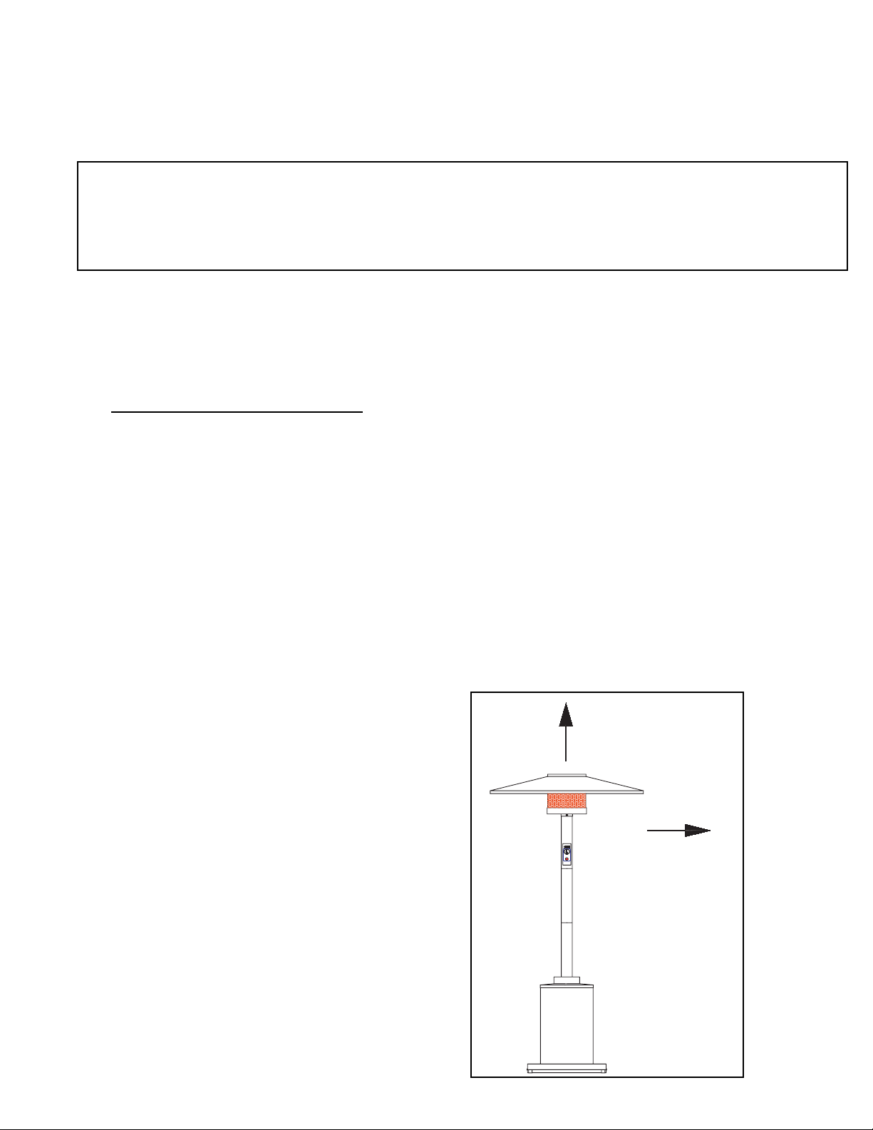
CHOOSING A LOCATION
The heater may be installed on a combustible
floor surface. If the heater is installed near a
combustible wall or ceiling surface, the following
minimum clearances must be maintained:
24 in. from any ceiling surface, and 36 in. from
any wall on all sides.
This appliance is CSA Certified for outdoor installation
only in a well ventilated space. The installation of this
appliance must conform with local codes or, in the
absence of local codes, with the National Fuel Gas
Code, ANSI Z223.1-Latest Edition. It must not be used
in a building, garage, or any enclosed area or structure.
The ground surface used for installation must be firm
and level, and allow adequate ventilation around the
unit (a minimum of 36 in. clear per side). At no time
should any part of the L.P. cylinder enclosure be
blocked off.
24" FROM ANY
CEILING SURFACE
36" FROM
ANY WALL
ON ALL SID
5
Page 6
WARNING
This product must be assembled and tested as shown in these
instructions. Any deviation or lack of testing could cause personal or
property damage. If you feel unable to assemble or test your heater as
described, have a qualified professional do it for you.
FOR TESTING INSTRUCTIONS SEE PAGE 11
COMMERCIAL
OUTDOOR HEATER
MODEL NO.:
HS-PC/GH/SH/SS
Tools Required
Phillips screwdriver, adjustable wrench / or pliers.
RR
Step 1
Unpack the box and flatten it out on the ground where you will be working. This will
provide you with a clean and non-abrasive work surface.
6
Page 7

COMMERCIAL OUTDOOR HEATER
CONTENTS PACKED IN (2) BOXES
BOX 2
BOX 1
HOOD
ASSEMBLY
HOOD CAP
PARTS
KIT
X 28
REFLECTOR HOOD
EMITTER
SCREEN
TANK SAFETY STRAP
BASE WITH WHEELS
X 12
REGULATOR
TANK CABINET
BASE
ASSEMBLY
PARTS
KIT
X 8
X 4
X 4
X 8
7
Substitutions may be made
X 5
X 12
Extra for
hood
Page 8

COMMERCIAL OUTDOOR HEATER
Step 2
Slip the connector hose through the two pieces of the heater post, as shown. The
connector will be factory assembled to the top heater post piece. Slide all three pieces
together and secure with the screws provide, as illustrated below. Make sure the holes
for the screws line up when sliding the pieces together.
X 8
BOTTOM
GAS HOSE PROTRUDES FROM THIS END
SCREW
LOCK WASHER X 8
X 8
&
CONTROLS
TOP
Step 3
Place the cabinet on the base so that the five holes in the cabinet line up with the
mounting holes on the base. Once the cabinet is in position, insert hex bolts and tighten
with wrench.
X 5
8
Page 9

COMMERCIAL OUTDOOR HEATER
Step 4
Carefully lower the assembled heater post
onto the cabinet. Open cabinet door. From
inside the cabinet, secure with four bolts
and washers with bolts facing upwards
towards post.
X 4
X 4
Step 5
While the cabinet door is open, locate the
tank strap mounting slots on the sides of
the cabinet. Install the tank safety strap
through these slots. Next locate the
Regulator and Hose. Attach to Gas Hose
and tighten with a wrench.
REGULATOR
TANK SAFETY STRAP
9
Page 10

COMMERCIAL OUTDOOR HEATER
Step 6
Open box 2, if you haven’t already done
so. Open Hood Assembly Parts Kit. Lay
out the (4) aluminum reflector hood pieces
and stainless steel hood cap, as illustrated.
HOOD CAP
REFLECTOR HOOD
X 8
HOOD CAP
Next, connect each reflector hood piece
together with the screws and flanged nuts.
With all reflector hood pieces and hood cap
attached, tighten.
First, attach each of the (4) reflector hood
pieces to the hood cap with the screws
provided. Do not tighten yet.
HOOD CAP
10
X 12
X 12
Page 11

COMMERCIAL OUTDOOR HEATER
Step 7
Turn the hood upside down on your cardboard work surface. Place the emitter screen in
the center of the hood and align the mounting holes. Insert (4) screws from the outside.
Tighten securely. Please note that the mesh band end of the emitter screen is placed
towards the burner, not the hood.
X 4
SIDE
VIEW
Step 8
Turn the hood/emitter screen assembly over
and place it on the heater post. Make sure
all four of the mounting tabs are inside the
emitter screen. Line up holes in screen with
tabs.
Install four screws and tighten securely.
ALIGN
MOUNTING
HOLES
X 4
MOUNTING HOLE
FOR SCREWS
11
Page 12

COMMERCIAL OUTDOOR HEATER
STEP 9 - TESTING PROCEDURE FOR PROPANE
• Prepare a cup of very soapy water.
• Attach Regulator to your L.P. Tank. Tighten securely with a wrench or the
handwheel (if provided). Leave the L.P. Tank outside of the Cabinet for the testing
procedure.
• Open the valve on the L.P. Tank. Leave the Heater Valve in the “OFF” position.
• With a brush or sponge, apply the soap and water mixture liberally to the union
(junction) between the Regulator and the L.P. Tank, and the union between the
Regulator and the Valve Fitting.
• Any leaks will blow soap bubbles.
• Repair any and all leaks by tightening union with wrench.
• Once any and all leaks have been stopped, the heater is ready for use!
DO NOT USE A FLAME
FOR LEAK TESTING
TESTING PROCEDURE FOR NATURAL GAS
• Prepare a cup of very soapy water.
• Attach heater gas hose to gas supply line. Tighten securely with a wrench .
• Open the gas supply line valve. Leave the Heater Valve in the “OFF” position.
• With a brush or sponge, apply the soap and water mixture liberally to the union
between the supply line and heater valve. Any leaks will blow soap bubbles.
• Repair any and all leaks by tightening union with wrench.
• Once any and all leaks have been stopped, the heater is ready for use!
DO NOT USE A FLAME
FOR LEAK TESTING
12
Page 13

COMMERCIAL OUTDOOR HEATER
WARNING:
GAS LEAKS ARE EXTREMELY DANGEROUS AND
POTENTIALLY EXPLOSIVE! DO NOT USE THIS PRODUCT
IF A LEAK CANNOT BE REPAIRED.
THE ABOVE TEST MUST BE PERFORMED EVERY TIME
THE L.P. TANK IS CHANGED.
IF YOUR HEATER DEVELOPS A LEAK THAT CANNOT BE
REPAIRED, YOU MAY REQUIRE REPLACEMENT PARTS OR
A NEW L.P. TANK. DISCONTINUE USE UNTIL THE NEW
PARTS ARE INSTALLED.
IF YOU SMELL GAS, DISCONTINUE USE UNTIL THE LEAK
IS IDENTIFIED AND REPAIRED.
Step 10
With the assembly and testing complete,
carefully place the L.P. Tank inside the
cabinet. Do not drag or push the tank
inside. This may cause damage to the
paint finish. Secure the tank safety strap
around the LP Tank.
Igniter Housing
Step 11
Battery Installation for Electronic
Contact Plate
Igniter
Unscrew Igniter Cap to access battery
compartment. Install AAA Battery with
positive (+) outward. Repalce Igniter
Cap, finger tight. Follow the lighting
instructions on the following page.
AAA Battery
Spring
Igniter Cap
13
Page 14

COMMERCIAL OUTDOOR HEATER
FOR YOUR SAFETY
READ BEFORE OPERATING
Important safety instructions which if not followed could endanger the personal safety
and/or property of yourself and others. Read and follow all instructions before attempting
to operate your Outdoor Heater.
The minimum inlet gas supply pressure for the purpose of input adjustment
pressure:
LP (Propane) Gas 11.2 inches w.c.
Natural Gas 10.0 inches w.c.
The maximum inlet gas supply pressure for the purpose of input adjustment
pressure:
LP (Propane) Gas 1/2 PSI
Natural Gas 1/2 PSI
The required manifold pressure in inches of water column:
LP ( Propane) Gas 10.0 w.c.
Natural Gas 7.0 inches w.c.
WARNING:
Certain materials or items when stored under the heater, will be subjected to radiant heat
and could be seriously damaged.
Lighting, shutdown and control operations:
After fully assembling your heater, turn on main gas supply and carefully recheck
all fittings for leakage using soap/water solution (see page 10).
If leak is discovered, turn off gas immediately. Repair seal on fitting with standard
pipe seal compound certified by a regulatory agency resistant to LP Gas.
A. Make certain main gas supply shut-off valve is in the “ON” position.
B. Push and turn gas control dial to “OFF” Position.
C. Wait sufficient length time to allow gas which may have accumulated to escape.
(at least 5 minutes)
D. Push and turn Gas Control Dial to “ON” (horizontal) position. Depress and hold dial in
while pushing the electronic igniter 3-4 seconds until pilot lights.
E. Allow burner to burn approximately 30 seconds before releasing dial. If pilot does
not remain burning when dial is released, repeat operation allowing longer period before
releasing dial. Wait a sufficient length of time (at least 5 minutes) to allow gas which may
have accumulated to escape. Repeat lighting instructions. If burner still will not light see
“TROUBLE SHOOTING”, (pages 16-17).
14
Page 15

COMMERCIAL OUTDOOR HEATER
Complete Shutoff:
Turn Gas Control Dial to “OFF” position and close the main gas supply shutoff valve on LP Tank or
the Natural Gas Supply source.
Warning:
The emitter and hood area becomes very hot during operation; stay away to avoid burns or clothing
ignition.
Young children should be carefully supervised when they are in the area of the heater.
Clothing or other flammable materials should not be hung from the heater, or placed on or near the
heater.
Any guard or other protective device removed while servicing the heater must be replaced prior to
operating the heater.
Installation and repair should be done by a qualified service person. The heater should be inspected
before use and at least annually by a qualified service person. More frequent cleaning may be
required as necessary. It is imperative that the control compartment, burner, pilot and circulating air
passageways of the heater be kept clean.
Maintenance:
Frequency checks:
A. Keeping the heater area clear and free from combustible materials, gasoline and other flammable
vapors and liquids.
B. Not obstructing the flow of combustion and ventilation air.
C. Keeping the ventilation openings of the cylinder enclosure free and clean from debris.
D. Visually inspect burner flames
Cleaning:
See page 19 for cleaning instructions.
Complete Shutoff:
Visually check the burner flame each time the
heater is used. Flames should be blue with
yellow tips.
Possible causes of a poor flame:
1. Burner is clogged. Remove and clean
the burner.
2. Air passageways clogged with debris
3. Tank is low. Refill tank.
15
Page 16

COMMERCIAL OUTDOOR HEATER
CONSTRUCTION DIAGRAM
Reflector Hood
Emitter Screen
Burner Enclosure
Manifold/Orifice
Safety Control Valve
Electronic Igniter
For models equipped for
natural gas, the hose is
passed through a hole in
the back of the cabinet.
Burner
Thermocouple
Pilot Light
Electrode
Heater Neck
L.P. Tank
(not included)
LP Safety Strap
Place heater on a firm and level surface
Flex Hose (Rubber)
& Gas Regulator
Cabinet conceals connections
and LP Tank
Heater Base with
Conceals Wheels
16
Page 17

COMMERCIAL OUTDOOR HEATER
TROUBLE SHOOTING
PROBLEM 1
Burner won’t remain lit.
CAUSE A
Possible Leak
SOLUTION
Check all connections
1. Use liquid soap to find leaks. Pour over
connection between hose and regulator and
regulator to tank. If soap bubbles, leaks are present.
* With all Propane tanks in the US, if a leak is
present the tank will automatically shut-down.
2. Use teflon tape on all connections.
3. Tighten all connections.
4. Check for leaks again. NEVER USE AN OPEN
FLAME TO CHECK FOR LEAKS.
4 Re-light heater to test.
TEST WITH
GAS ON
AND REGULATOR
CONNECTED
TEST FOR
LEAKS HERE
CAUSE B
Thermocouple may be too tight on valve.
* If thermocouple is too tight on valve, it will limit the
amount of millivolt electricity, which keeps the valve
flowing gas.
SOLUTION
Loosen Thermocouple
1.Remove cover opposite side the control knob with
phillips screwdriver.
2. With a wrench, loosen thermocouple connection
to valve (Copper lead with 1/4” flare fitting)
3. Hand tighten and slightly tighten with wrench. Do
NOT torque or over tighten.
4. Re-light heater to test.
CAUSE C
Tilt mechanism disconnected
*Your Heater has several safety features that
are connected via wires to the thermocouple.
Sometimes during movement or shipping, these may
become disconnected.
SOLUTION
Check inside of burner neck that all wires are
connected.
FRONT BACK
THERMOCOUPLE
21
LOOSEN
BACK
17
Page 18

COMMERCIAL OUTDOOR HEATER
TROUBLE SHOOTING
PROBLEM 2
Large Yellow Candling Flame
CAUSE
This can occur after a period of non-use. Most likely
debris, dirt or a spider web has gotten into the orifice.
SOLUTION
CLEAN THE ORIFICE
1. Remove the hood and emitter by removing the (4)
screws that attach the emitter screen to the burner plate.
2. For easier access, also remove the top section of the
post. This can be accomplished by first removing the
regulator from the hose. Then remove the top neck
portion from the post.
3. With phillips screwdriver, remove the four screws
holding the burner plate to the powder coated neck post.
Pull the burner plate away from the post neck and slightly
tilt to the side. Be careful not to crimp any tubes or wires.
Damaging any tubes may create a leak.
4. The Orifice will now be exposed.
5. Examine for debris, dirt or spider webs and clean as
necessary.
* Make sure not to push obstruction farther down orifice.
6. Once cleaned, re-assemble burner plate to neck post,
making sure all wires and tubes are safely slid back into
the neck. Re-tighten the four screws in place.
7. Re-attach Top Neck Post to rest of heater assembly..
Attach regulator to gas hose. Make sure to use teflon tape
when re-attaching regulator.
8. Check for leaks (refer to Solution for Problem 1, Cause
A).
9. Re-light heater to test.
1
3
ORIFICE
REMOVE THE (4) SCREWS
HOLDING THE BURNER PLATE
TO THE POST NECK, PULL BURNER
PLATE AWAY AND TILT TO ACCESS
2
ORIFICE
Please also reference the Instruction Manual for any
reference to assembly.
18
Page 19

COMMERCIAL OUTDOOR HEATER
TROUBLE SHOOTING
PROBLEM 3
Ignitor not lighting pilot
CAUSE A
Electrode not creating a sufficient enough spark to
ignite the gas
SOLUTION
CHECK SPARK GAP AND ELECTRODE
CONNECTIONS
1. Remove the hood and emitter by removing the (4)
screws that attach the emitter screen to the burner
plate.
2. Check the spark gap and adjust as illustrated.
3. Check all Electrode wire connections.
PROBLEM 3
Ignitor not lighting pilot
CAUSE B
Igniter AAA Battery not installed properly or without
power.
SOLUTION
CHECK BATTERY INSTALLATION OR USE NEW
BATTERY
1. See Page 13, Step 11 to install battery properly or
replace battery.
2. Check all igntier wires to make sure connected.
3. Trying lighting heater again while making sure gas is
flowing through the pilot.
About 1/4” to 3/8” spark gap between
Electrode and Thermocouple
Igniter Housing
Contact Plate
AAA Battery
Spring
19
Igniter Cap
Page 20

COMMERCIAL OUTDOOR HEATER
CARE & CLEANING
Cleaning the Heater
Follow the Trouble Shooting Guide for CLEANING THE ORIFICE. This should be done at least once
a year, more if a problem occurs.
Open the Heater Access Plate, located opposite of the Controls and clean any debris from inside the
neck. Make sure to pay special attention to the valve and ignitor.
The Emitter Screen can be cleaned with products like Oven Cleaners.
Cleaning the exterior surfaces and hood
You can wash your heater just like a car. Use mild detergent and rinse with water.
Keeping your heater clean allows it to operate and provide years of service.
If a scratch occurs in a powder coated surface, quickly touch-up with an exterior acrylic based paint.
Touching up will lessen the possibility of rusting in that area.
20
 Loading...