

Page 1
D
GB
F
NL
SIEPDK
GARDENA
®
V 2 Art. 1253
V1 Art. 1252
D Gebrauchsanweisung
Bewässerungsventil
GB Operating Instructions
Irrigation Valve
F Mode d’emploi
Bloc-vanne
NL Gebruiksaanwijzing
Beregeningsventiel
S Bruksanvisning
Ventildosa
I Istruzioni per l’uso
Valvola cordless
E Manual de instrucciones
Válvula de riego
P Instruções de utilização
Válvula de Irrigação
DK Brugsanvisning
Vandingsventil
Page 2
10 11
GB
GB
Intended use
Please note
Contents
GARDENA Irrigation Valve V1 / V 2
Welcome to the Garden of GARDENA...
Please read these operating instructions carefully and observe
the notes given. Use these operating instructions to familiarise
yourself with the Irrigation Valve, its correct use and the notes on
safety.
For safety reasons, children under 16 as well as persons not
familiar with these operating instructions should not use this
Irrigation Valve.
v Please keep these operating instructions in a safe place.
1. Where to Use Your GARDENA Irrigation Valve
. . . . . . . . . . . . . 10
2. For Your Safety . . . . . . . . . . . . . . . . . . . . . . . . . . . . . . . . . . . . . . . . . . . . . 11
3. Assembly . . . . . . . . . . . . . . . . . . . . . . . . . . . . . . . . . . . . . . . . . . . . . . . . . . . 11
4. Operation . . . . . . . . . . . . . . . . . . . . . . . . . . . . . . . . . . . . . . . . . . . . . . . . . . . 14
5. Maintenance
. . . . . . . . . . . . . . . . . . . . . . . . . . . . . . . . . . . . . . . . . . . . . . . . 14
6. Trouble-Shooting . . . . . . . . . . . . . . . . . . . . . . . . . . . . . . . . . . . . . . . . . . . 15
7. Protection against Frost . . . . . . . . . . . . . . . . . . . . . . . . . . . . . . . . . . . . 15
8. Accessories . . . . . . . . . . . . . . . . . . . . . . . . . . . . . . . . . . . . . . . . . . . . . . . . 16
9. Technical Data . . . . . . . . . . . . . . . . . . . . . . . . . . . . . . . . . . . . . . . . . . . . . . 16
10. Service
. . . . . . . . . . . . . . . . . . . . . . . . . . . . . . . . . . . . . . . . . . . . . . . . . . . . . 16
1. Where to Use Your GARDENA Irrigation Valve
This Irrigation Valve, in conjunction with the Programming Unit
1242 and the Control Unit 1250 or with the Central Radio Control
Unit 1243 and the Radio Receiver 1244/ 1245, forms part of a
watering system for your garden.
1242 1250
1243 1244/ 1245
The Watering Valves are intended solely for outdoor use for fully
automatic control of individual irrigation systems. It is a benefit
to arrange a watering system into separate sections in case
of varying watering needs for different plant areas or if there is
insufficient water available for simultaneous operation of the
entire watering system.
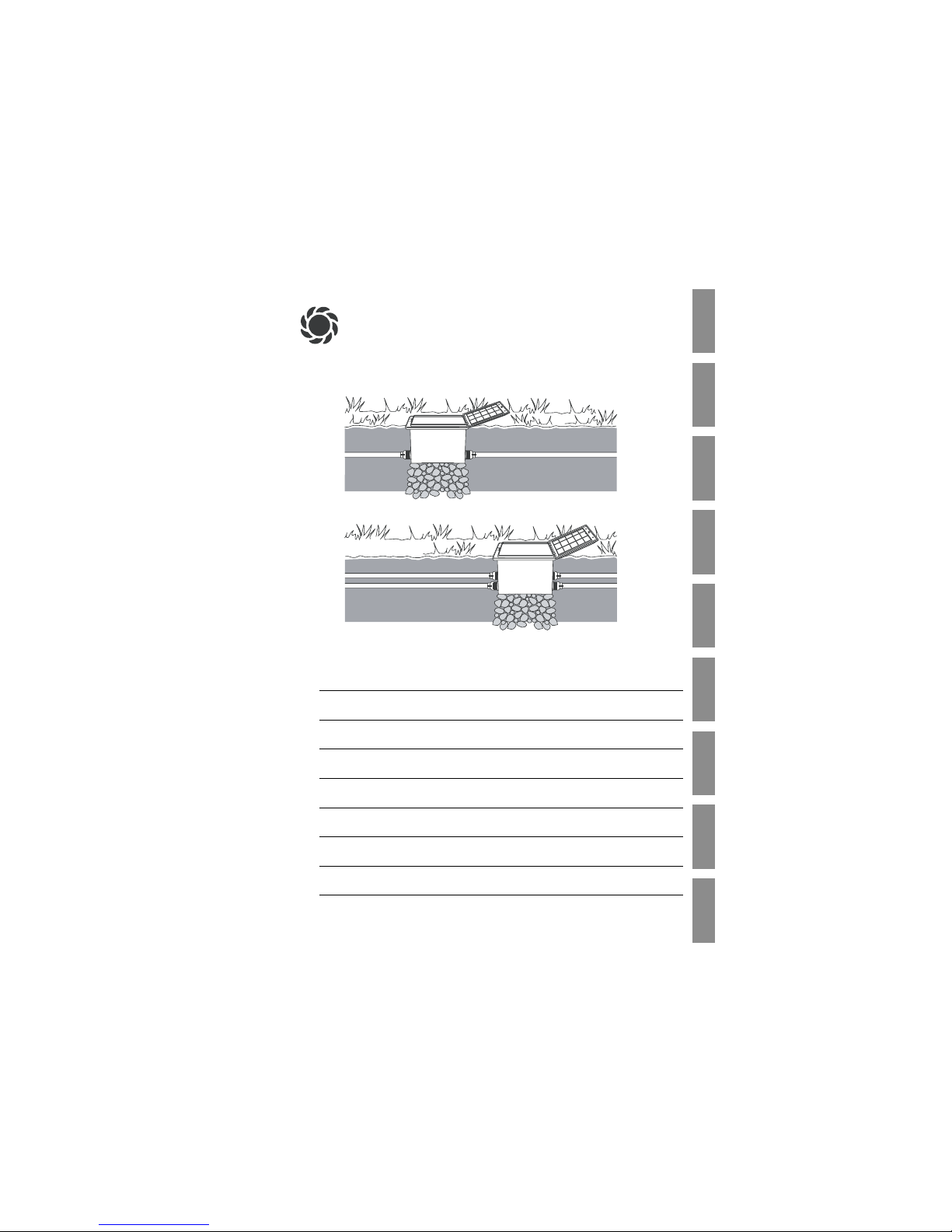
The Irrigation Valve is installed upstream in the watering system
(e. g. Pop-up Sprinklers; Micro-Drip-System), for example, in the
ground.
Compliance with the enclosed operating instructions provided by
GARDENA is a prerequisite for proper use of the Irrigation Valve.
The Irrigation Valve must only be used in conjunction with the
Control Units / Radio Receivers approved by GARDENA.
2. For Your Safety
v Pay attention to the safety notes on the valve box.
Warning!
V Please read the operating instructions before using the
Irrigation Valve for the first time.
Winter Storage
V Before the frost period starts : see point 7. Protection
against Frost, “Winter storage”.
v Please observe the notes on safety in the operating instruc-
tions.
V In the case of dir ty, sandy or contaminated water, the
GARDENA Central Filter Art. No. 1506 must be installed
upstream in the watering system.
The function of your watering system depends on the available
water pressure. Therefore, care should be taken not to overlap
watering cycles of the various watering circuits and to ensure
that the watering circuits you have planned will be supplied with
sufficient water at an adequate pressure.
Please refer to the planning instructions in the packaging of Popup Sprinklers or the special brochure entitled “Watering Systems
– Sprinkler System Planning Guide” available from GARDENA.
Blocking the
Irrigation Valve
Water pressure
Install the valve box:
3. Assembly
The Irrigation Valve is installed below ground level, however it can
also be used above the ground.
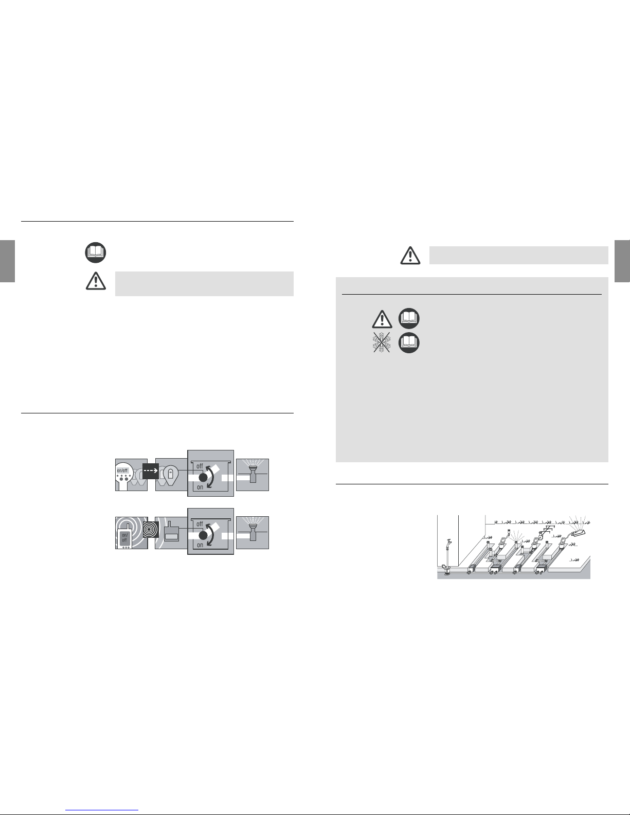
1. Draw up a plan (an example is shown in the figure below).
Additional information is provided in the GARDENA Sprinkler
System Planning Guide which is available from your GARDENA
dealer.
Page 3

12 13
GB
GB
If you connect several Irrigation Valves to one water supply, then
each pipe must be flushed separately in order to obtain an adequate flushing pressure. To do this :
1. Push the short telescopic pipe Ainto the nipple on the inletside 5which is not to be flushed.
2. Push the bracket
0
into the elongated holes of the nipple on
the inlet-side 5.
The short telescopic tube Ais fixed in place.
3. Screw the end cap Bonto the short telescopic pipe A.
The integrated solenoid valve only works correctly with the
Irrigation Valve connected in flow direction.
Flow direction
A V Pay attention to the flow direction (arrows) when
assembling the Irrigation Valve C.
1. Push the long telescopic pipe 8all the way into the nipple
on the outlet-side
5
a.
2. Screw the short telescopic pipe Ainto the inlet side of the
Irrigation Valve C.
The arrows on the Irrigation Valve point in the flow direction.
3. Push the short telescopic pipe Ainto the nipple on the inletside 5.
4. Screw the long telescopic pipe
8
into the outlet-side of the
Irrigation Valve C.
5. Push the bracket 0into the elongated holes of the nipples
5/5
a.
The telescopic pipes 8/Aare fixed in place.
When you open the box lid Dyou can see the flow direction
marked by the arrows on the Irrigation Valve C.
v The box lid Dcan be locked by turning the lever Eby 90°.
The box lid Dcan be locked as a protection against theft.
v Overlap the holes Fof the valve box and the box lid and lock
using a small padlock
– or –
alternatively, the lid
D
can be safeguarded against theft using
a sheet metal screw (4.2 x 19).
In conjunction with the programmed watering time, the moisture
level of the soil or the natural precipitation can be taken into
account for each Irrigation Valve.
When a sufficient moisture content of the soil is reached, a programme may be interrupted or activation of a programme may
be suppressed.
Close off nipple
on inlet-side:
Assemble the
Irrigation Valve:
Lock the box lid:
Connect Soil Moisture
Sensor or Rain Sensor
electronic (optional) :
B
A
0
5
E
F
D
z
5a
0
A C 85
Connect GARDENA connecting pipes to valve box:
Flash the system:
2. For underground installation, place a layer of course gravel
1
approx. 20 x 30 x 10 cm3(V 1) / 30 x 35 x 10 cm3(V 2) underneath the valve box.
This ensures proper drainage of the box.
3. Install the valve box with the top edge of the box at ground
level.
This avoids damage when mowing the lawn.
You can use the GARDENA Connecting Pipe Ar t. No. 1580/
15823and GARDENA Hose Clips Art. No. 1591 2to connect
the valve box.
1. Push the nipples
5
from the inside into the box openings.
2. Fasten the nipples 5to the valve box from the outside using
the nuts 6.
3. Screw a tap connector 4on each nipple 5.
4. Push a hose clip 2over each pipe end 3.
Tip: Place the pipe ends 3in warm water to make it easier to
push the ends of the pipes 3onto the tap connectors 4.
5. Push the connecting pipes
3
onto the tap connectors 4and
secure with the hose clips 2.
Note: You can also attach a GARDENA Connector Art. No.
2745/ 27497(1"= 25 mm / 5/ 4"= 32 mm) to the nipples 5for
connecting hard connecting pipes or other commercially available connecting pipes.
After connecting the pipes to the valve box, the system must be
flushed.
Flushing the system after routing the pipes prevents contaminating
the valves.
1. Push the long telescopic pipe
8
all the way into the nipple
on the outlet-side 5a.
2. Push the flushing pipe 9into the nipple on the inlet-side 5.
3. Push the bracket 0into the elongated holes of the nipple on
the inlet-side 5.
The flushing pipe 9is fixed in place.
4. Screw the long telescopic pipe 8onto the flushing pipe 9.
5. Turn on the water supply at the nipple 5.
The system is flushed.
6. Remove the flushing pipe 9.
1
1
z
5a
0
5 9 8
2 3 4
4
4
5
5
6
6
6
6
77
Page 4

14 15
GB
GB
1. Place the Soil Moisture Sensor Gin the area to be irrigated
– or –
the Rain Sensor electronic (if necessary with an extension
cable) outside of the area to be irrigated
2. Thread the connecting cable
I
of the sensor Gthrough one
of the two stopper slits H.
3. Adjust the cable length Iin the box as required.
4. Press the stopper Hback into box wall.
5. Plug the connector Jinto the sensor socket Kof the Control
Unit / Radio Receiver.
4. Operation
Fully Automatic Control:
v Set selection lever
L
to “AUTO/ OFF”.
Programme-controlled water flow to the watering system according to the programming in the Control Unit / Radio Receiver.
An automatically opened valve cannot be closed manually.
Manual Control:
v Set selection lever Lto “ON”.
Permanent water flow,
independent of the programming
.
5. Maintenance
The foam inlay Nof the draining outlet prevents insects
(especially ants) from entering.
v Please contact your nearest GARDENA Service Centre
for replacing the foam inlay N.
The box lid is step-proof and
attached to the box by hinges.
1. Open the box lid
D
.
2. Push the lid Dbackwards
and out of the hinges O.
3. Fit the new lid in the reverse
order.
Adjusting valve control:
Replacing the foam inlay:
Replacing the box lid:
G
J
H
I
K
J
H
I
L
Winter storage
6. Trouble-Shooting
Fault Possible Causes Remedy
Solenoid valve does not Control Unit / Radio Receiver v Connect Control Unit /
open, no water flow not connected correctly to Radio Receiver correctly
solenoid valve. to solenoid valve.
No water supply. v Turn on water supply.
Pipe closed. v Remove end cap B.
Solenoid valve does not Solenoid valve installed v Turn solenoid valve in box
close, continuous water flow opposite to flow direction. (observe the flow direction).
Selection lever Lset to “ON”. v Set selection lever Lto
“AUTO/ OFF”.
Pipe slides off nipple Hose clips2are too loose. v Tighten hose clips
2
(see “3. Assembly”).
If other faults occur, please contact GARDENA Customer Service.
7. Protection against Frost
Valves can be easily removed from the box.
The following precautions must be taken – especially before the
frost period starts – to prevent damage to the Irrigation Valves
and the entire watering system:
1. Close the water tap and disconnect the hose from the
GARDENA Water Connection Point Art. No. 1594.
This allows air to flow freely.
2. If the watering system is directly connected to the water tap,
turn off the water supply and open the venting tap.
3. Set the selection lever Lof all valves to the “ON” position.
4. Empty the system (e.g. using compressed air)
– or –
on slopes remove the valve located at the lowest level
and store safe from frost
– or –
remove all valves and store safe from frost.
5. After removing the valve, install the flushing pipe
9
(see “3. Assembly”,
“Flush the system”
).
Prevents dirt collecting in the system.
6. Remove the battery from the Control Unit / Radio Receiver.
7. Lock the box lid (see “3. Assembly”,
“Lock the box lid”
).
N
O
O
D
L
9
Page 5

16
GB
8. Accessories
GARDENA Connecting Pipe • Art. No. 1580/ 1582
GARDENA Hose Clip • Art. No. 1591
GARDENA Radio Receiver R2/R4 • Art. No. 1244/ 1245
GARDENA Control Unit • Art. No. 1250
GARDENA Soil Moisture Sensor • Art. No. 1187
GARDENA Rain Sensor electronic • Art. No. 1189
GARDENA Extension Cable for
Soil Moisture Sensor and
Rain Sensor electronic • Art. No. 1186
GARDENA Central Filter • Art. No. 1506
9. Technical Data
Solenoid Valve
Operating pressure 1 to 12 bar
Flow medium clean fresh water
Max. water temperature 40 °C
10. Service
GARDENA guarantees this product for 2 years (from date of
purchase). This guarantee covers all serious defects of the unit
that can be proved to be material or manufacturing faults. Under
warranty we will either replace the unit or repair it free of charge
if the following conditions apply:
• The unit must have been handled properly and in keeping with
the requirements of the operating instructions.
• Neither the purchaser or a non-authorised third party have
attempted to repair the unit.
Faults with the Irrigation Valve caused by incorrectly installed
batteries or leaking batteries in the Control Unit / Radio Receiver
are not covered by the guarantee.
This manufacturer’s guarantee does not affect the user’s existing
warranty claims against the dealer/ seller.
If a fault occurs with your Irrigation Valve, please return the
faulty unit together with a copy of the receipt and a description
of the fault, with postage paid to one of the GARDENA Service
Centres listed on the back of these operating instructions.
We expressly point out that, in accordance with the product
liability law, we are not liable for any damage caused by our
units if it is due to improper repair or if parts exchanged are not
original GARDENA parts or parts approved by us, and, if the
repairs were not carried out by a GARDENA Service Centre or
an authorised specialist. The same applies to spare parts and
accessories.
Connection
Control
Filter
Warranty
Product Liability
Page 6

Deutschland
GARDENA Kress + Kastner GmbH
GARDENA Service
Hans-Lorenser-Straße 40
D-89079 Ulm
Produktfragen: (07 31) 490- 123
Reparaturen: (07 31) 490- 290
Argentina
Argensem S.A.
Venezuela 1075
(1618) El Talar - Buenos Aires
Australia
NYLEX Consumer Division
76- 88 Mills Road
P.O. Box 722
Braeside 3195
Melbourne, Victoria
Austria
GARDENA Österreich Ges. m.b.H.
Stettnerweg 11-15
2100 Korneuburg
Belgium
MARKT (Belgium) NV/SA
Sterrebeekstraat 163
1930 Zaventem
Brazil
M. Cassab
Av.das Nações Unidas, 20.882
Santo Amaro, CEP 04795-000
São Paulo - S.P.
Bulgaria / България
ДЕНЕКС ООД
Бул. ”Г.М.Димитров” 16 ет.4
София 1797
Canada
GARDENA Canada Ltd.
100 Summerlea Road
Brampton, Ontario
Canada L6T 4X3
Chile
Antonio Martinic Y CIA. LTDA.
Gilberto Fuenzalida 185 Loc.
Las Condes - Santiago de Chile
Costa Rica
Compania Exim
Euroiberoamericana S.A.
Av.12 bis Calle 16 y 18
Bodegas Keith y Ramirez
San José
Cyprus
FARMOKIPIKI LTD
P.O. Box 7098
74, Digeni Akrita Ave.
1641 Nicosia
Czech Republic
GARDENA spol. s.r.o.
Шнpskб 20a, и.p. 1153
62700 Brno
Denmark
GARDENA Danmark A/ S
Naverland 8
2600 Glostrup
Finland
Habitec Oy
Martinkyläntie 52
01720 Vantaa
France
GARDENA France
Service Après-Vente
BP 50080
95948 ROISSY CDG Cedex
Great Britain
GARDENA UK Ltd.
27- 28 Brenkley Way
Blezard Business Park
Seaton Burn
Newcastle upon Tyne NE13 6DS
Greece
Agrokip G. Psomadopoulos & Co.
33a, Ifestou str.
Koropi 194 00
Athens
Hungary
GARDENA Magyarország Kft.
Késmárk utca 22
1158 Budapest
Iceland
Heimilistaeki hf
Saetun 8
P.O. Box 5340
125 Reykjavik
Republic of Ireland
Michael McLoughlin & Sons
Hardware Limited
Long Mile Road
Dublin 12
Italy
GARDENA Italia S.r.l.
Via Donizetti 22
20020 Lainate (Mi)
Japan
KAKUDAI Mfg. Co. Ltd.
1-4 -4, Itachibori Nishi-ku
Osaka 550
Luxembourg
Magasins Jules Neuberg
Grand Rue 30
Case Postale No.12
Luxembourg 2010
Netherlands
GARDENA Nederland B.V.
Postbus 50176
1305 AD ALMERE
Neth. Antilles
Jonka Enterprises N.V.
Sta. Rosa Weg 196
P.O. Box 8200
Curaçao
New Zealand
NYLEX New Zealand Limited
Private Bag 94001
South Auckland Mail Centre
10 Offenhauser Drive
East Tamaki, Manukau
Norway
GARDENA Norge A/ S
Postboks 214
2013 Skjetten
Poland
GARDENA Polska Sp. z o.o.
Szymanów 9 d
05- 532 Baniocha
Portugal
GARDENA, Lda.
Recta da Granja do Marquês
Edif. GARDENA
Algueirão
2725-596 Mem Martins
Russia / Россия
АО АМИДА ТТЦ
ул. Моcфилмовcкая 66
117330 Моcква
Singapore
Variware
Holland Road Shopping Centre
227-A 1st Fl., Unit 29
Holland Avenue
Singapore 1027
Slowenia / Croatia
Silk d.o.o. Trgovina
Brodišče 15
1236 Trzin
South Africa
GARDENA South Africa (Pty.) Ltd.
P.O. Box 11534
Vorna Valley 1686
Spain
ANMI Andreu y Miriam S.A.
Calle Pere IV, 111
08018 Barcelona
Sweden
GARDENA Svenska AB
Box 9003
20039 Malmö
Switzerland
GARDENA Kress + Kastner AG
Bitziberg 1
8184 Bachenbülach
Ukraine / Украина
АОЗТ АЛЬЦЕСТ
ул. Гайдара 50
г. Киев 01033
Turkey
Dost Diþ Ticaret Mümessillik A.Þ.
Yeþilbaðlar Mah.Baþkent
Cad. No. 26
Pendik - Ýstanbul
USA
GARDENA
3085 Shawnee Drive
Winchester, VA 22604
1252-20.960 .04/ 0021
©
GARDENA Kress + Kastner GmbH
Postfach 27 47, D-89070 Ulm
http: //www.gardena.com
 Loading...