

Gardena CF 5000 S, CF 8000 S, 7889, 7890 Operating Instructions Manual
D
GB
S
DK NL
FI
E
P
D Betriebsanleitung
UVC-Mehrkammerfilter-Set
GB Operating Instructions
UV multi-chamber filter set
F Mode d’emploi
Kit de filtration UVC multi-compartiments
NL Gebruiksaanwijzing
UVC-meerkamerfilter-Set
S Driftsanvisningarna
UV multi-kammar filterset
DK Driftsvejledning
UV multi-kammer filtersæt
I Istruzioni per l’uso
Set filtro UVC multi-camera
E Instrucciones de empleo
Kit de filtrado UVC multi-compartimentos
P Manual de instruções
Conjunto filtro UVC multi-compartimentos
CF 5000 S Art. 7889
CF 8000 S Art. 7890
11
GB
GARDENA UV Multi-Chamber Filter Set
CF 5000 S / CF 8000 S
Translation of the original German operating instructions.
Please read the operating instructions carefully and observe the
notes given. Use the operating instructions to familiarise yourself
with the correct usage of the UV Multi-Chamber Filter Set, and
the notes on safety.
v Keep these operating instructions in a safe place.
Contents: 1. Range of use for your GARDENA
UV Multi-Chamber Filter Set . . . . . . . . . . . . . . . . . . . . . . . . . 11
2. Safety Instructions . . . . . . . . . . . . . . . . . . . . . . . . . . . . . . . . . 11
3. Function . . . . . . . . . . . . . . . . . . . . . . . . . . . . . . . . . . . . . . . . . 13
4. Assembly . . . . . . . . . . . . . . . . . . . . . . . . . . . . . . . . . . . . . . . . 13
5. Initial Operation . . . . . . . . . . . . . . . . . . . . . . . . . . . . . . . . . . . 14
6. Putting out of Operation . . . . . . . . . . . . . . . . . . . . . . . . . . . . 14
7. Maintenance. . . . . . . . . . . . . . . . . . . . . . . . . . . . . . . . . . . . . . 15
8. Trouble-Shooting . . . . . . . . . . . . . . . . . . . . . . . . . . . . . . . . . . 15
9. Technical Data . . . . . . . . . . . . . . . . . . . . . . . . . . . . . . . . . . . . 17
10. Service / Warranty . . . . . . . . . . . . . . . . . . . . . . . . . . . . . . . . . 18
1. Range of use for your GARDENA UV Multi-Chamber Filter Set
The GARDENA UV Multi-Chamber Filter Set is intended for private
use in domestic gardens and allotments and should only be used
out of doors for cleaning garden ponds with and without fish.
CF 5000 S: CF 8000 S:
for ponds with a volume of for ponds with a volume of
up to 5000 l without fish / up to 8000 l without fish /
2500 l with fish / 4000 l with fish /
1250 l with koi 2000 l with koi
The GARDENA UV Multi-Chamber Filter Set cleans the pond
water biologically and mechanically and reduces the growth of
algae. Algae is bound together and pathogens (particularly in
fish ponds) are destroyed.
The GARDENA UV Multi-Chamber Filter Set is not suitable
for industrial use or in combination with chemicals, food,
easily combustible and explosive substances.
Please note:
Purpose:
For safety reasons, children under 16 as well as persons not
familiar with these operating instructions should not use this
UV Multi-Chamber Filter Set.
v Comply with the safety instructions on the UV unit.
2. Safety Instructions
WARNING!
v Read the operating
instructions before
using the equipment for the first time!
DANGER!
v Ultraviolet radiation.
Protect eyes from flash.
13
GB
12
GB
This radiation is harmful to eyes and skin.
v Never operate the UV unit when the
housing has been removed.
Electrical safety:
v Inspect the equipment before use to
ensure that the pump and the UV unit,
especially the power cable and plug,
are undamaged.
Do not use a damaged UV unit or
pump.
If the power cable, glass tube, or the
housing of the UV device appear to be
defective, the UV device must not be
operated.
If the pump or UV unit is damaged, please
have them checked by our GARDENA Service
Centre or an authorised electrician.
The UV-unit and the pump must be
operated via a residual-current device
(Fl-switch) with a nominal fault current ≤ 30 mA
(DIN VDE 0100-702 and 0100-738).
v Please ask your electrician for his advice.
Mains power cables should not have
a smaller cross-section than a rubber
sheathed cable of the designation H05 RNF.
Extension cables must meet the
requirements of DIN VDE 0620.
The information on the model plate of the
UV unit must match the power supply.
The connection cable of the UV-unit
and the pump cannot be replaced.
If the cable is damaged the UV unit must
be scrapped.
Do not use extension leads, connection leads
or adapters without a protective contact.
The fountain pump must not be operated
when there are people in the water.
Swimming pools and garden ponds should
be designed according to international and
national design regulations.
v Please ask your electrician for his advice.
Never carry the UV-unit and the pump by
the cable. Do not pull on the cable to unplug
the plug from the socket.
Please protect the cable from heat, oil and
sharp edges. Make sure that connection
points remain dry.
Always unplug the equipment when
dismantling the set, when it is not in use
and before maintenance.
v Always disconnect the UV unit and the
pump from the mains before undertaking
any work on them.
For Austria:
In Austria power cables should correspond
to ÖVE-EM 42, T2 (2000)/1979 § 22 according
to § 2022.1. According to this standard units
used in swimming pools and ponds should
only be operated via an isolating transformer.
v Please contact your electrician.
For Switzerland:
In Switzerland mobile appliances which
are used outdoors, must be connected via
a residual-current device.
Notes:
Never operate the UV unit without water
throughput.
Never let the pump run dry; running dry
generates heat and will damage the pump.
Sand and other abrasive substances in the
liquid cause increased wear and reduce the
output of the pump.
The temperature of the liquid used must not
be below 4 °C or above 35 °C.
Safety switch:
If the UV light overheats, it is switched off by
the built-in thermal protection switch. The UV
light switches itself on again automatically
when it has cooled down sufficiently.
Due to the integrated safety switch the lamp
only comes on when the UV unit is properly
installed.
Positioning the filter:
v Stand or bury the filter housing in a stable
position at least 2 m away next to the
garden pond.
The filter must be positioned higher than the
surface of the pond.
Bacterial Activity:
Extensive bacterial activity arises from + 10 °C
onwards.
The filter system is a biological system and
therefore, when newly installed, needs a few
weeks until it is fully effective.
If possible, the filter should be in permanent
operation from spring to autumn and should
not dry out.
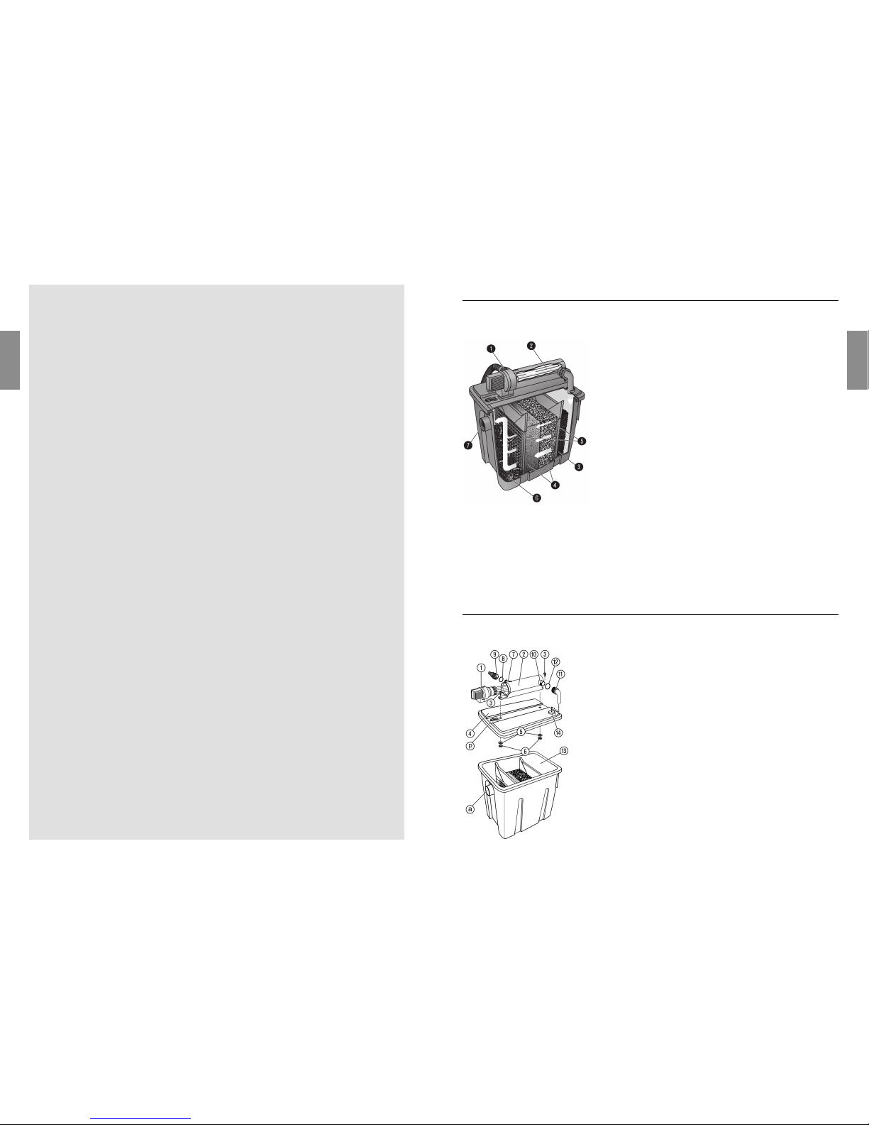
3. Function
!
Water intake
Universal connection for the pump supply hose in the pond.
"
Phase 1 – UV-radiation
The pond water, which has already undergone preliminary treatment, is subjected to short wave UV-light (ultraviolet rays). During
this process, the algal growth is reduced and germs which cause
disease in fish ponds are killed.
§
Phase 2 – Water calming and the filtration of coarse conta-
minants. The water is calmed by the Japanese mat and coarse
contaminants are caught and kept there.
$
Phase 3 + 4 – Biological cleaning and the filtration of fine
contaminants
• Blue filter sponge / bio-surface elements:
This promotes the growth of aerobic micro-organisms which
guarantee the conversion of ammonia into nitrate via nitrite
(nitrification).
• Black filter sponge:
This supports the growth of anaerobic micro-organisms which
promote denitrication (reduction of nitrate to nitrogen).
%
Phase 5 – Flow direction
The partitioning walls influence the flow direction and speed.
&
Phase 6 – Biological cleaning
Through the organic surface elements, the growth of aerobic
micro-organisms is promoted, which guarantees the conversion
of ammonia into nitrate via nitrite (nitrification).
/
Water discharge
Water discharge DN 50 for the return flow of the cleansed water.
4. Assembly
1. Turn UV unit head 1of the UV unit 2anti-clockwise 1
and remove carefully 2 (bayonet fitting)
(see 8. Trouble-Shooting “Changing the bulb”).
2. Attach the shaped discharge tube qto the UV outlet 0by
screwing on the washer w.
3. Push the two bolts 3into the guides on the UV unit 2and
place on the filter cover
4
.
4. From underneath, screw one washer 5and one nut
6
respec-tively on to the bolts 3and screw the UV unit
2
firmly on to the filter cover 4.
5. Push the filter cover 4with the UV device 2onto the
filter housing
e
, so that the arrow
ß
p
is positioned above
the outlet
ß
a
.
6. Insert UV bulb and fit UV unit
(see 8. Trouble-Shooting “Changing the bulb”).
7. Screw the universal connection nipple 9on to the UV outlet
7
with the O-Ring 8.
Assembling the
UV Multi-Chamber Filter:
 Loading...