

Page 1
GARDENA
®
Art. 1243
D Gebrauchsanweisung
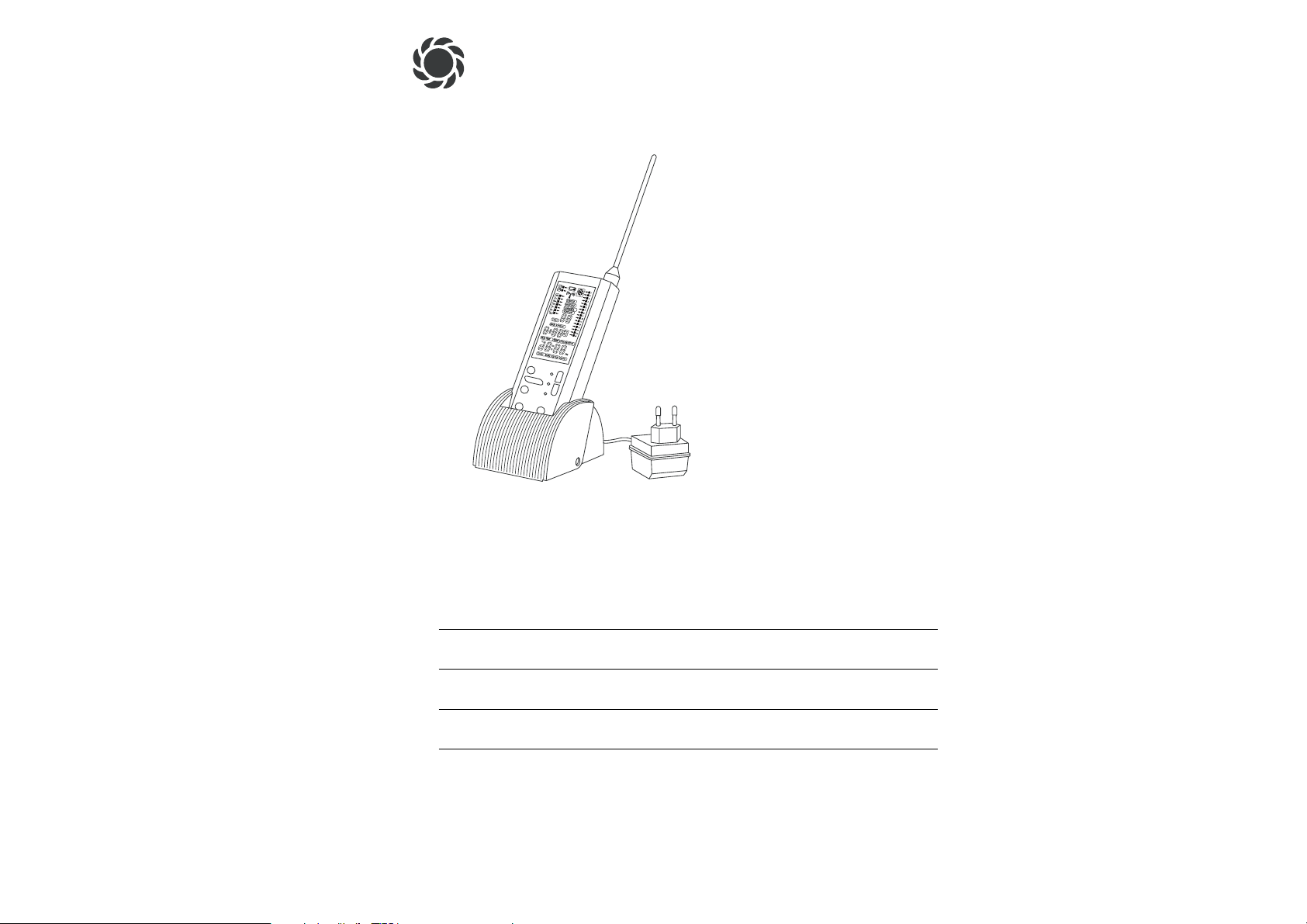
Funkzentrale
GB Operating Instructions
Central Radio Control Unit
F Mode d’emploi
Télécommande
NL Gebruiksaanwijzing
Afstandsbediening met houder
I Istruzioni per l’uso
Centralina radio-trasmittente
Page 2
19
G
Intended use
GARDENA Central Radio Control Unit
Welcome to the Garden of GARDENA...
Please read these operating instructions carefully and observe
the notes given. Use these instructions to familiarise yourself with
the Central Radio Control Unit, its correct use and the notes on
safety.
For safety reasons, children under the age of 16 as well as persons not familiar with these operating instructions should not use
this Central Radio Control Unit.
v Please keep these operating instructions in a safe place.
1. Where to Use Your GARDENA Central Radio Control Unit
. . 19
2. For Your Safety . . . . . . . . . . . . . . . . . . . . . . . . . . . . . . . . . . . . . . . . . . . . . 20
3. Key Functions and Display . . . . . . . . . . . . . . . . . . . . . . . . . . . . . . . . . . 21
4. Quick Reference Operating Instructions . . . . . . . . . . . . . . . . . . . . . 22
5. Creating a Control Plan
. . . . . . . . . . . . . . . . . . . . . . . . . . . . . . . . . . . . . 23
6. Labelling Irrigation Valves and Radio Switch . . . . . . . . . . . . . . . . 24
7. Operating the Control Systems . . . . . . . . . . . . . . . . . . . . . . . . . . . . .
24
8. Special Functions
. . . . . . . . . . . . . . . . . . . . . . . . . . . . . . . . . . . . . . . . . . . 28
9. Trouble-Shooting . . . . . . . . . . . . . . . . . . . . . . . . . . . . . . . . . . . . . . . . . . . 33
10. Putting Out of Operation
. . . . . . . . . . . . . . . . . . . . . . . . . . . . . . . . . . . . 33
11. Technical Data
. . . . . . . . . . . . . . . . . . . . . . . . . . . . . . . . . . . . . . . . . . . . . . 34
12. Service
. . . . . . . . . . . . . . . . . . . . . . . . . . . . . . . . . . . . . . . . . . . . . . . . . . . . . 34
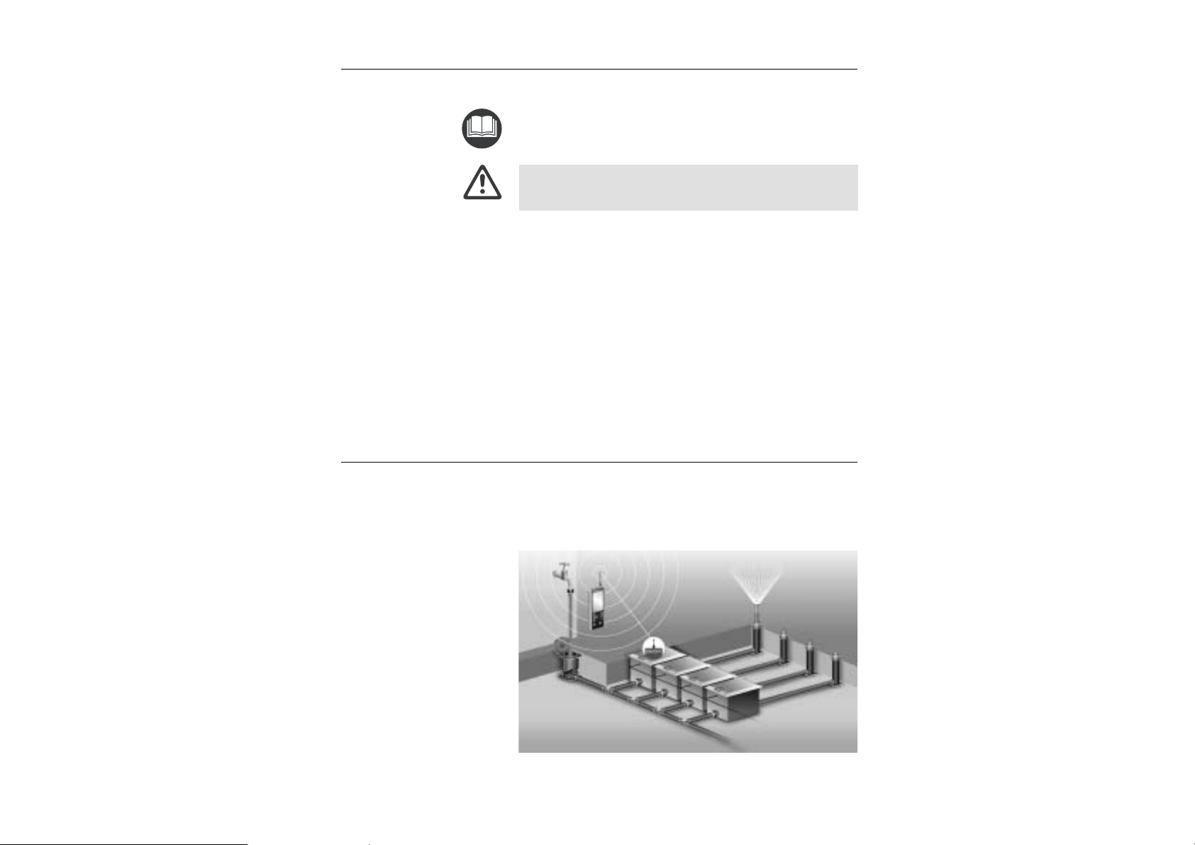
1. Where to Use Your GARDENA Central Radio Control Unit
This Central Radio Control Unit is part of a controlling system
and can be used to control the following receivers:
• Radio Receiver Art. 1244/1245 in combination with Irrigation
Valves Art. 1251 /1252/ 1253 allows fully-automatic control of
watering systems with several subsystems.
• Radio Switch Art. 1246 for controlling 230 V electrical devices
such as a garden pump for supplying water for an irrigation
system, outdoor lighting or a pond pump.
Contents
Page 3
21
G
20
G
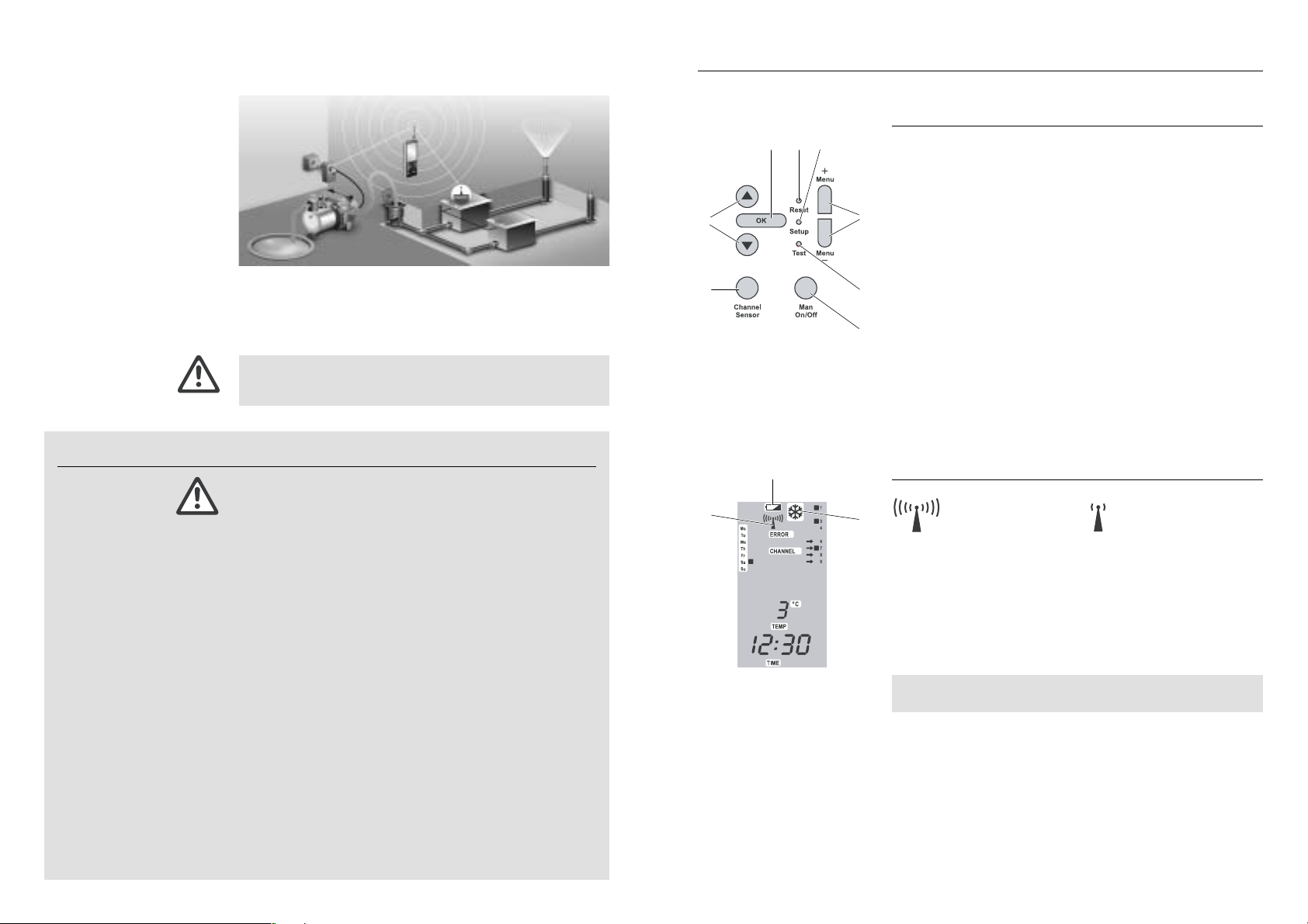
3. Key Functions and Display
Key Functions
Key Function
1
▲ / ▼ For changing or advancing specific data already
entered. (If you hold down one of the ▲-▼ keys
the display runs through the hours or minutes,
for example, more quickly.)
2
OK Confirms the values set using the ▲-▼ keys.
3
Reset Deletes all data (reset).
4
Setup For the system settings
(e.g. registering receivers).
5
Menu + / Changes the display level
Menu – (main level, time level, programme level).
6
Test Activates the test functions (e.g. battery status).
7
Man For opening or closing individual channels
On/Off manually (test radio range).
8
Channel Changes display from channels to sensors
Sensor and sensor configuration.
System Displays
Radio Reception Display 9:
is displayed
ERROR and V flashing
= good reception = poor reception
Battery Status Display of Central Radio Control Unit:
If the voltage falls below a certain level, the battery status
display 0of the Central Radio Control Unit flashes until the
battery is replaced.
Battery Status Display of Radio Receiver:
If the voltage falls below a certain level, the battery status
display
0
and the arrows V in front of the channels of the
Radio Receiver flash until the battery is replaced.
If the battery status display flashes the valves are closed automatically.
Frost Warning Display:
If the temperature of a receiver falls below +5°C, the frost
warning symbol
A
and the arrows V before the channels of
the receiver flash and the Central Radio Control Unit beeps.
v Press the OK key to confirm the frost warning.
The control signals are transmitted to the receiver. Frequent data
transfer between the Central Radio Control Unit and the Receiver
ensures reliable operation.
There is no danger of interference with other 433 MHz devices
(e.g. garage door opener) or other radio remote controls (e.g.
owned by your neighbours).
Compliance with the operating instructions provided by GARDENA
is a prerequisite for proper use of the Central Radio Control Unit.
The Central Radio Control Unit must only be used for controlling
the Radio Receiver for GARDENA Irrigation Valves and the
Radio Switch.
Please note
2. For Your Safety
Only use four 1.5-volt alkaline AA batteries to achieve the specified maximum operating time when the unit is not connected to
the mains. We recommend Varta and Energizer batteries.
The LCD display may go blank if the outside temperature falls
below – 10°C or rises above 60 °C. This has no effect whatsoever on data storage or the correct transfer of data. The LCD
display will function normally again when the outside temperature returns to the normal operating range (– 10 °C to 50 °C).
v If the battery status symbol flashes on the display you must
replace the batteries immediately.
To ensure good radio reception, position your Central Radio
Control Unit near a window if you prefer to keep it indoors.
The range of the radio control unit depends on the material that
must be penetrated. Concrete walls or buildings made of sheet
metal can limit the range considerably.
Extreme weather conditions (fog, rain) can also restrict the
range.
v Protect the Central Radio Control unit against moisture.
The Radio Receivers are installed in the valve boxes of the
Irrigation Valves and are safe against flooding.
The valve box must be installed such that is it safe against
flooding.
v Always ensure that the cover is closed.
LCD display:
Central Radio Control Unit:
Radio Receiver:
9
0
A
3
8
7
6
42
5
1
Page 4

23
G
22
G
The 3 Display Levels
Main Level Time Level Programme Level
Changing the Display Level:
v Press the Menu + key.
The display changes to the next level.
If you do not press another key within 2 minutes, the main level
appears automatically on the display.
4. Quick Reference Operating Instructions
v Enter the data for the watering programmes on the control plan
(see Appendix).
v Label the irrigation valves and radio switches corresponding to
the channels of the watering plan using the stickers provided.
1. Mount aerial.
2. Connect the Central Radio Control Unit to the mains via the
power pack and insert the batteries (use 1.5-volt alkaline AA
batteries only).
The batteries prevent loss of data if a power failure occurs.
1. Set the hours using the ▲-▼ keys and confirm by pressing
the OK key.
2. Set the minutes using the ▲-▼ keys and confirm by pressing
the OK key.
3. Set the day of the week using the ▲-▼ keys and confirm
by pressing the OK key.
1. Press the Setup key (e.g. using the tip of a pen).
2. Insert batteries in just one
Radio Receiver
– or – just one Radio Switch.
3. Set channel number(s) using the ▲-▼ keys and confirm
by pressing the OK key.
4. Repeat steps 1 to 3 for each receiver until you have registered
all receivers.
1. Press the Menu + key twice.
2. Select the programme memory location using the ▲-▼ keys
and confirm by pressing the OK key.
1. Create control plan:
2. Label irrigation valves
and radio switches:
3. Put Central Radio Control
Unit into operation:
4. Enter current time
and day of the week:
5. Register Receiver:
6. Set the Control Programme
(
PROG
):
5. Creating a Control Plan
v Enter the data of the watering programme in the control plan
(see appendix).
Example of a Control Plan:
Receiver Channels PROG START-TIME RUN -TIME 3rd 2nd Mo Tu We Th Fr Sa Su Sensors
Sprinkler-
1 1 5:00 1:00 X 1
System
2 2 7:00 1:00 X 1
3 3 18:00 1:00 X 1
Micro-Drip-
4 19:00 0:30 XXXXXXX 4
System
4
5 6:00 0:30 XXXXXXX 4
Lightline 5 6 20:00 2:00 XXXXXXX –
Pond
7 9:00 3:00 XXXXXXX –
pump
6
8 13:00 5:00 XXXXXXX –
Garden
pump
M– – – –
1. Set the hours for the programme start time using the ▲-▼ keys
and confirm by pressing the OK key.
2. Set the minutes for the programme start time using the ▲-▼
keys and confirm by pressing OK.
1. Set the hours for the programme run time using the ▲-▼ keys
and confirm by pressing OK.
2. Set the minutes for the programme run time using the
▲-▼ keys and confirm by pressing OK.
Every 2nd or 3 rd day:
v Set the arrow L to 2
nd
or 3rdusing the ▲-▼ keys and confirm
by pressing OK.
Any day of the week:
v Set the arrow L to the correct day using the ▲-▼ keys and
confirm the day by pressing OK.
1. Set the arrow V to the channel you require using the ▲-▼ keys
and activate the channels by pressing OK.
2. Press Menu + to return to the program selection screen.
1. Press the Man On / Off key.
2. Set the V to the channel using the ▲-▼ keys and open or close
the channel by pressing OK.
The opening time is set to 30 minutes as a default but the opening
time can be set manually as required (see 8.1
Opening/Closing
Channel Manually
).
7. Set programme start time
(
START-TIME
):
8. Set the programme run time
(
RUN-TIME
):
9. Set the watering days :
10. Assign the programme
to the channels:
11. Manual Operation :
Page 5

25
G
24
G
6. Labelling Irrigation Valves and Radio Switch
v Label the Irrigation Valves and Radio Switches using the stick-
ers provided with the irrigation valves. Match them to the corresponding channels on the control plan.
This ensures that the channels are assigned to the radio receivers
and radio switches in a clear, unambiguous way. This is particularly
important when you begin to use your irrigation installation again
in the spring.
(For example: Sprinkler-System = channel 1, 2 and 3,
Lightline = channel 5)
7. Operating the Control System
Do not install the batteries in the Radio Receivers yet and/
or plug the Radio Switch into the mains.
V If necessary remove the batteries from the Radio
Receivers and/or unplug the Radio Switches.
7.1 Putting the Central Radio Control Unit
into Operation
1. Push the aerial provided to the Central Radio Control Unit.
2. Connect the Central Radio Control Unit to the cable of the
power supply provided and plug the mains cable into a mains
socket (230 V)
– and –
install batteries in the Central Radio Control Unit.
The Central Radio Control Unit beeps and
TIME
and the
00
for the hours flash on the display.
3. (a) Set up the support on a suitable surface or
(b) fasten the support to the wall.
Insert the batteries in the Central Radio Control Unit:
The Central Radio Control Unit is designed to be mains-operated.
The batteries prevent loss of data if a power failure occurs.
The batteries have a limited working life if the Central Radio Control Unit is disconnected from the mains power or if a power outage occurs. In order to operate your Central Radio Control Unit
without power from the mains, you must install four 1.5-volt alkaline
(AA) batteries (do not use rechargeable batteries). These batteries
are no longer used as soon as you connect your Control Unit to the
mains.
1. Slide out the cover
B
on the back of the Central Radio Control
Unit and remove the battery pack
C
.
2. If necessary, remove flat batteries from the battery pack
C
and insert new batteries Din the correct position (pay attention
to the +/– markings on the battery pack and the batteries).
3. Fit the battery pack Cthe right way round in the Central Radio
Control Unit (pay attention to the +/– markings on the Central
Radio Control Unit and the battery pack
E
).
4. Slide the cover Bback into place and close the battery com-
partment.
2.
3. (a) (b)
C
D
D
C
B
– +
E
If you replace the batteries when the Control Unit is not connected to the mains you will reset the unit.
TIME and
00
for the hours
flash on the display and you must enter the time and day (refer
to section 7.2
Setting the Current Time and Day of the Week
).
Before installing the batteries in the Radio Receiver and/ or
plugging the Radio Switch into the mains, you must activate the
registering mode of the Central Radio Control Unit. The receivers
are then registered automatically (refer to section 7.3
Registering
Receivers
).
You must also insert four 1.5-volt AA batteries in the Radio
Receiver Art. 1244 /1245 (see operating instructions for Radio
Receiver). The Radio Switch Art. 1246 does not require batteries
because it is connected directly to a mains socket.
7.2 Setting the Current Time and Day of the Week
1. Set the hours using the ▲-▼ keys (for example
11 22
hours)
and confirm by pressing the OK key.
TIME
and the minutes flash on the display.
2. Set the minutes using the ▲-▼ keys (for example
3300
minutes)
and confirm by pressing the OK key.
TIME
and the day flash on the display.
3. Set the day using the ▲-▼ keys (for example Sa ■ Saturday)
and confirm by pressing the OK key.
The main level is displayed.
7.3 Registering Receivers
1. Press the Setup key (using the tip of a pen, for example) to
call the registering mode of the Central Radio Control Unit.
SETUP
is displayed and the free channels flash on the display.
2. Install batteries in just one Radio Receiver
– or –
plug in just one Radio Switch.
The Radio Receiver or Radio Switch is registered automatically (for example 4-channel Radio Receiver).
The receiver identification number (e.g.
227788
) is displayed and
the channels of the receiver flash (e.g. channel V ■1 to V ■ 4 ).
Possible appearance of display when registering a receiver:
4-channel 2-channel 1-channel
Radio Receiver Radio Receiver Radio Receiver
3. Set the channel number(s) according to the control plan using
the ▲-▼ keys (for example, ■ 6 to ■ 9) and register the channels by pressing the OK key.
The registered channels no longer flash.
3.
1.
2.
3.
Main Level
1. 2.
Page 6

27
G
26
G
Setting the watering days:
(a) every 2ndor 3rdday (from current day)
(b) select any day (daily watering possible)
7. (a) Every 2nd or 3rd day :
Set the arrow L to 2
nd
or 3rdusing the ▲-▼ keys (e.g. 2ndL
= every 2nd day) and confirm by pressing the OK key.
The watering days (e.g.
2nd■
) and preview for the week
(e.g.
Sa■,Mo■ ,We■,Fr■ )
are displayed.
The days in the preview for the week depend on the current
day of the week (e.g. Sa).
– or –
(b) Any day of the week:
Set the arrow L to the correct day (e.g.Mo L) using the
▲-▼ keys and activate (e.g. Mo ■ L) or deactivate the day
using the OK key.
Once you have activated all the days you require (e.g. Mo■,
Tu ■,We■), press the ▼ key repeatedly until the arrow L
next to Su disappears and appears in front of channel V 1.
The preview for the week (e.g.
Mo■,Tu■,We■
) for the water-
ing days is displayed.
Assigning the Programme to the Channels:
The programme only controls only the assigned channels.
8. Set the arrow V to the channel you require using the ▲-▼ keys
(e.g. V 3 = channel 3) and activate (e.g. V■ 3) or deactivate
the channel by pressing the OK key.
Once you have activated all the channels you require (e.g. ■ 3
and ■ 8), Press the Menu + key.
The display then changes to point 2 and the current programme
data are displayed.
The receivers must be registered and the levers of the Irrigation
Valves must be set to the “AUTO” position in order to run the
set programmes.
4. Repeat steps 2 and 3 until all receivers are registered.
5. Press the Menu – key.
The main level is displayed.
6. Test the radio range (refer to section 7.4
Testing the Radio
Range
).
7.4 Testing the Radio Range
1. Install the radio receivers/radio switches as required
(do not bury the valve boxes yet).
2. Test the Central Radio Control Unit in that room in which
you plan to install the bracket for the control unit.
3. Open and close the channels manually to check they work
correctly (refer to 8.1
Opening and Closing Channels Manually
).
4. Once you have established radio contact, bury the valve boxes
and permanently install the holder for the Central Radio Control
Unit.
7.5 Setting the Control Programme
Prerequisite: You must have set the current time and current
day. The receivers must not be registered. All programmes are
saved when receivers are cancelled.
Selecting the Programme Memory Location (PROG):
The Control Unit can store 32 programmes.
1. If the main level is displayed, press the Menu+ key twice.
Programme Memory Location 11flashes.
2. Select the programme memory location using the ▲-▼ keys
(for example, memory location
11 88
) and confirm by pressing
the OK key.
START-TIME
and the hours flash on the display.
Setting the Programme Start Time (START- TIME) :
3. Set the hours for the programme start time using the
▲-▼ keys (e.g.
11 66
hours) and confirm by pressing the OK key.
START- TIME
and the minutes flash on the display.
4. Set the minutes for the programme start time using the
▲-▼ keys (e.g.
2200
minutes) and confirm by pressing the
OK key.
RUN-TIME
and the hours flash on the display.
Setting the Programme Run Time (RUN-TIME) :
5. Set the hours for the programme run time using the ▲-▼ keys
(e.g.22hours) and confirm by pressing the OK key.
RUN-TIME
and the minutes flash on the display.
6. Set the minutes for the programme start time using the
▲-▼ keys (e.g.
4455
minutes) and confirm by pressing the
OK key.
CHANNEL a
nd the arrow Lflash in the top left-hand corner
of the display next to
3rd.
1. 2.
3. 4.
5. 6.
7. (a)
7. (b)
8.
Page 7

29
G
28
G
8.5 Cancelling Receivers
1. Press the Setup key (e.g. using the tip of a pen).
SETUP
is displayed and the free channels flash on the display.
2. Press the Menu + key (display/ register receivers).
An arrow Vis displayed before the first registered receiver 11.
(e.g.11= first receiver, V■ 1)
3. Press the ▲-▼ keys repeatedly until OFF and the arrow V
before the desired receiver start to flash (e.g.
33
= third receiver,
V■ 6 to V■ 9).
4. Press the OK key to cancel the receiver.
The symbols ■are deleted and the receiver is cancelled.
An arrow Vis displayed before the first receiver 11that is still
registered (e.g.
V■ 1
).
8.6 Master Channel
The master channel is a channel that is activated in conjunction
with other channels. This is important, for example, if an irrigation
system is supplied with water by a pump that should be turned
on whenever one of the irrigation valves is activated.
Registering Radio Receivers / Radio Switches as the
Master Channel:
1. Press the Setup key (e.g. using the tip of a pen) to enter the
registering mode for the Central Radio Control Unit.
SETUP
is displayed and the free channels flash on the display.
2. Install batteries in the Central Radio Control Unit or plug the
radio switch you want to register as the master channel into
the Control Unit.
The radio receiver or radio switch is then registered automatically.
3. Set the master channel M using the ▲-▼-keys and register
by pressing the OK key.
The radio receiver / radio switch is
registered as the master channel.
Assigning the Master Channel:
1. Register the master channel (see 7.3
Registering Receivers
).
2. Press the Setup key (e.g. using the tip of a pen).
SETUP
is displayed and the free channels flash on the display.
3. Press the Menu + key repeatedly until MASTER appears on the
display and the V in front of the first registered channel flashes.
4. Select the channel using the ▲-▼ keys and deactivate (e.g.
V 11) or activate the master channel by pressing the OK key.
8. Special Functions
8.1 Opening/ Closing Channels Manually
Prerequisite:
All receivers must be registered and the levers of the Irrigation
Valves must be set to the “AUTO” position.
1. Press the Man On / Off key.
MAN
is displayed and the arrow Vflashes.
The channels flash until the radio connection is established.
It may take up to 60 seconds to establish a connection.
2. Set the arrow V to the channel you require using the ▲-▼ keys
and open the channel (e.g. V■ 7) or close the channel (e.g.
V 7) by pressing the OK key.
The symbol ■appears in front of the open channel and the opening time
RUN-TIME
(e.g.
00::3300
) is displayed.
If a channel is opened manually, the hours for the opening time
and
RUN-TIME flash for 5 seconds. You can change the opening
time during these 5 seconds. The opening time can be set
between
00::0011
and
99::5599
.
3. Change the hours for the opening time within 5 seconds using
the ▲-▼ keys (e.g.11) and confirm by pressing the OK key.
4. Change the minutes for the opening time using the ▲-▼ keys
(e.g.
11 00
) and confirm by pressing the OK key.
5. Press Man On/ Off to end manual operation.
The main level is displayed.
Programmes which are scheduled to run during this manual
opening time are indicated by PROG and are not interrupted.
8.2 Changing Current Time and Day of the Week
1. Press the Menu + key.
The time level is displayed.
2. Change the time and / or the day (refer to section 7.2
Setting
the Current Time and Day of the Week
).
8.3 Changing an Existing Programme
If a programme already exists on one of the 32 programme
memory locations, you can make changes to this programme
without having to create the programme again from scratch.
The values for the programme start time, run time and cycle
and the assigned channels are pre-set. Therefore, you only
need to alter the values you want to change.You can accept the
values you do not want to change by simply pressing the OK key.
8.4 Ending the Programming Mode Early
v Press the Menu + key twice.
The programming mode is closed and the changes you have
entered are saved.
The main level appears.
1. 2.
3. 4.
2. 3.
1. 2.
3. 4.
Page 8

31
G
30
G
3. Set the arrow V to the sensor you require (e.g. V 7 =
sensor 7) using the ▲-▼ keys and assign the sensor to the
channel (e.g. V■ 7) by pressing the OK key.
4. Once you have assigned all the sensors you require (e.g. ■ 1
and ■ 7), to the channel (e.g. channel
99
) press the Menu +.
The display then changes to point 2 again and the channel and
the sensors assigned to this channel are displayed.
8.10 Temperature Sensor
Each radio receiver is equipped with a temperature sensor in
addition to the connected sensors. The temperature of the connected receiver is displayed in the main level.
1. Select the radio receiver In the main level using the ▲-▼ keys.
TEMP
is displayed and the arrows Vflash next to the selected
radio receiver.
2. Confirm by pressing OK (e.g. radio receiver V 6 to V 9).
The temperature is displayed as -- ° C until the radio receiver has
transferred the current temperature of the Central Radio Control
Unit (e.g.
2255
°C).
8.11 Channel and Sensor View
The main level can be displayed in the channel or sensor view.
v Press the Channel Sensor key to change the view.
a) Channel View:
CHANNEL and all channels that are switched on are displayed
(e.g. channels 1, 3 and 7 are switched on ■ 1, ■ 3 and ■ 7).
b) Sensor View :
SENSOR and all sensors that are switched on are displayed,
e. g. Soil Moisture Sensor = moist
(e.g. sensors 3 and 9 are switched on = ■ 3 and ■ 9).
8.7 Changing the Default Manual Opening Time
The default value for the manual opening time can be set
between
00::0011
and
99::5599
. The Central Radio Control Unit is
pre-set to
00::3300
.
1. Press the Setup key (e.g. using the tip of a pen).
SETUP
is displayed and the free channels flash on the display.
2. Press and hold down the Man On / Off key for approx.
3 seconds.
MAN
and
RUN-TIME
are displayed and the hours of the opening
time flash.
3. Set the hours for the opening time using the ▲-▼ keys
(e.g.
11
) and confirm by pressing the OK key.
4. Set the minutes for the opening time using the ▲-▼ keys
(e.g.
1100
) and confirm by pressing the OK key.
8.8 Changing the PIN
The 3-digit PIN (Personal Identification Number) which can be
set between
000000
and
9999 99
, prevents unauthorised access to
your watering programmes.You are only asked to enter your PIN
if the number is not
000000
.
1. Press the Setup key (e.g. using the tip of a pen).
SETUP
is displayed and the free channels flash on the display.
2. Press and hold down the Channel Sensor key for approx.
3 seconds.
PIN
is displayed and the first number of the PIN flashes.
3. Set the first number of your PIN using the ▲-▼ keys (e.g.99)
and confirm by pressing the OK key.
4. Change the second digit (e.g.77) and the third digit (e.g.33)
in the same way as for the first digit.
When you have changed the PIN, the main level appears on
the display again.
8.9 Operating the Sensors
After registering the receiver, each channel is assigned its own
sensor (sensor 16 (M) was registered together with channel M).
The sensors can also be assigned to the channels individually.
This is useful, for example, if you want to control the entire irrigation system using a rain sensor or soil moisture sensor.
1. Press and hold down the Channel Sensor key for 2 seconds.
SENSOR
is displayed, Channel 11and
CHANNEL
flash on the
display.
2. Select the channel using the ▲-▼ keys (e.g. channel 99)
and confirm by pressing the OK key.
SENSOR
and the arrow Vnext to sensor 1 (
V 1
) flash on
the display.
1. 2.
3. 4.
3. 4.
3. 4.
1. 2.
a) b)
Page 9

33
G
32
G
9. Trouble-Shooting
Fault Possible Cause Remedy
Radio Receiver cannot be The batteries are not installed v Install the batteries as de-
registered correctly in the battery compart- scribed in the Radio Re-
ment. ceiver operating instructions.
The unit reset itself A brief power cut occurred v Install batteries (see
while you were operating the 7.1 Putting Your Central
Central Radio Control Unit Radio Control Unit into
without batteries. Operation).
The active channels are The Central Radio Control Unit v Change the Central Radio
not displayed displays the Sensor screen. Control Unit to the Channel
screen (see 8.11 Channel
and Sensor Screen).
No display Power pack not connected v Connect power pack to
to mains. mains.
No battery fitted or battery flat. v Install battery (refer to
7.1.
Putting the Central
Radio Control Unit into
Operation
).
Outside temperature below v Wait until outside tempera– 10 °C or above + 50 °C. ture returns to operating
temperature range.
Battery flat after operating Batteries are not alkaline v Use 1.5-volt alkaline AA
Central Radio Control Unit batteries. batteries.
for short period of time
Power pack not connected v Connect power pack to
to mains. mains.
Error during data transfer Radio Receiver/ Switch not v Connect Radio Receiver/
connected or not connected Switch correctly.
correctly.
ERROR flashes on the display Poor radio reception. v Reduce distance to receiver.
(data transfer error)
and channel flash Low battery power in Radio v Replace battery in Radio
on the display Receiver. Receiver.
v Please also refer to the Trouble-Shooting table for the
Irrigation Valves and Radio Receivers.
If other faults occur, please contact GARDENA Customer Service.
10. Putting Out of Operation
v Remove the valves from the valve boxes and store in a place
away from frost before the first frost sets in.
v Remove the batteries from the Radio Receivers and close the
battery cover properly.
This prevents water from penetrating the Radio Receivers.
Only dispose of batteries when flat.
v Please dispose of used batteries properly at the appropriate
communal waste disposal site.
Wintering:
Putting the System
out of Operation:
Important
8.12 Testing the Receiver and Sensor Status
1. Press the Test key (e.g. using the tip of a ball-point pen).
TEST
is displayed and Vflashes on the display in front of
the first registered receiver. (The channels of the receiver
flash until radio contact is established.)
2. Select the receiver using the ▲-▼ keys (e.g. V 6 to V 9)
and confirm by pressing the OK key.
The following Receiver stati are displayed:
• Radio signal strength (radio mast symbol, see 3.
Key Functions
and Display
)
• Battery voltage (e.g.
5588
= 5.8 V)
(The battery should be replaced if the battery voltage is < 4.5 V.)
• Receiver temperature (e.g.
2255
°C)
• Receiver number (e.g.
227788
)
The following sensor stati are displayed:
• Sensor connected and detects “moisture”:
■ symbol displayed
(e.g. sensors 1 and 4 = ■ 1 and ■ 4)
• Sensor not connected : ■ off
(e.g. sensors 3, 6, 7 and 9 = 3, 6, 7 and 9)
• Only for Soil Moisture Sensor Art. 1187:
connected and dry: ■ flashes
(e.g. sensor 8 dry = ■ 8 flashes)
“Connected” and “dry” are not displayed with the Rain Sensor
electronic Art. 1189 (■ off).
8.13 Reset
The Central Radio Control Unit is reset to its initial
A state and all programme data is deleted.
You can reset the Central Radio Control Unit in three ways:
1. Connect to mains (when using unit for the first time)
– or –
2. Insert batteries in Central Radio Control Unit (when not connected to the mains)
– or –
3. Reset key (e.g. using the tip of a ball-point pen.)
The unit can be reset from all operating levels by pressing
the Reset key.
• All symbols appear on the display for 2 seconds.
• All programme data for all programmes is deleted.
• All receivers are cancelled.
• The manual run time is set to 30 minutes (
00::33 00
).
• The PIN number is reset to
000000
.
The display then shows the time level.
Tip: If you have questions about operating and programming
the Central Radio Control Unit, please do not hesitate to contact
GARDENA Service.
1. 2.
Page 10

35
G
Warranty
Product Liability
EU Certificate of Conformity
The undersigned GARDENA Kress + Kastner GmbH · Hans-Lorenser-Str. 40 · D-89079 Ulm
hereby certifies that, when leaving our factory, the unit indicated below is in accordance with
the harmonised EU guidelines, EU standards of safety and product specific standards.
This certificate becomes void if the unit is modified without our approval.
Description of the unit: Central Radio Control Unit
Art. No. : 1243
EU directives: Electromagnetic Compatibility 89/ 336 / EC
Low Voltage Directive 73/23/ EC
Directive 93/68 / EC
Harmonised European
standards: ETS 300683:1997; EN 60730-1:1996
Year of CE marking: 2000
Ulm, 15.06.2000 Thomas Heinl
Technical dept. manager
34
G
11. Technical Data
External power supply: power pack 12 V DC
Internal power supply: 4 x 1.5-volt alkaline AA batteries (max. 1 week)
Radio range (outside) : up to 200 m
Transmit/ receive frequency: 433 MHz
Transmitter power : < 10 mW
Operating temperature: from frost to + 50 °C
Storage temperature: – 10 °C to + 60°C
Air humidity: 20 % to 95% relative humidity
Receiver / sensor management: max. 16
Programme saved when battery changed: yes (EEPROM)
12. Service
GARDENA honours the guarantee legally required for this product (starting from the date of purchase). This guarantee covers
all serious defects of the unit that can be proved to be material
or manufacturing faults. Under warranty we will either replace the
unit or repair it free of charge if the following conditions apply:
• The unit must have been handled properly and in keeping with
the requirements of the operating instructions.
• Neither the purchaser or a non-authorised third party have
attempted to repair the unit.
• Faults which occur as a result of incorrectly installed or leaking
batteries are not covered by the guarantee.
This manufacturer’s guarantee does not affect the user’s existing
warranty claims against the dealer/seller.
If you have any problems with your Central Radio Control Unit,
please contact our Customer Service or return the defective unit
together with a short description of the problem directly to one
of the GARDENA Service Centres listed on the back of this
leaflet.
We expressly point out that, in accordance with the product
liability law, we are not liable for any damage caused by our units
if it is due to improper repair or if parts exchanged are not original
GARDENA parts or parts approved by us, and, if the repairs were
not carried out by a GARDENA Service Centre or an authorised
specialist. The same applies to spare parts and accessories.
Page 11

9190
Receiver Channels PROG START-TIME RUN -TIME 3 rd 2nd Mo Tu We Th Fr Sa Su Sensors Receiver Channels PROG START-TIME RUN -TIME 3 rd 2nd Mo Tu We Th Fr Sa Su Sensors
Page 12

Deutschland
GARDENA Kress + Kastner GmbH
GARDENA Service
Hans-Lorenser-Straße 40
D-89079 Ulm
Produktfragen: (07 31) 490 -123
Reparaturen: (07 31) 490 - 290
Argentina
Argensem S.A.
Venezuela 1075
(1618) El Talar - Buenos Aires
Australia
NYLEX Corporation Ltd.
25-29 Nepean Highway
P.O. Box 68
Mentone, Victoria 3194
Austria
GARDENA Österreich Ges. m.b.H.
Stettnerweg 11-15
2100 Korneuburg
Belgium
MARKT (Belgium) NV/SA
Sterrebeekstraat 163
1930 Zaventem
Brazil
M. Cassab
Av. das Nações Unidas, 20.882
Santo Amaro, CEP 04795-000
São Paulo - S.P.
Bulgaria / България
ДЕНЕКС ООД
бул. „Черни връх“ 43
София 1407
Canada
GARDENA Canada Ltd.
100, Summerlea Road
Brampton, Ontario
Canada L6T 4X3
Chile
Antonio Martinic Y CIA. LTDA.
Gilberto Fuenzalida 185 Loc.
Las Condes - Santiago de Chile
Costa Rica
Compania Exim
Euroiberoamericana S.A.
350 Sur del Automercado
Los Yoses
San Pedro
Cyprus
FARMOKIPIKI LTD
P.O. Box 7098
74, Digeni Akrita Ave.
1641 Nicosia
Czech Republic
GARDENA spol. s.r.o.
Ripská 20
62700 Brno
Denmark
GARDENA Danmark A/S
Naverland 8
2600 Glostrup
Finland
Habitec Oy
Martinkyläntie 52
01720 Vantaa
France
GARDENA France
Service Après-Vente
BP 50080
95948 ROISSY CDG Cedex
Great Britain
GARDENA UK Ltd.
27- 28 Brenkley Way
Blezard Business Park
Seaton Burn
Newcastle upon Tyne
NE13 6DS
Greece
Agrokip G. Psomadopoulos & Co.
20, Lykourgou str.
Kallithea - Athens
Hungary
GARDENA Magyarország Kft.
Késmárk utca 22
1158 Budapest
Iceland
Heimilistaeki hf
Saetun 8
P.O. Box 5340
125 Reykjavik
Republic of Ireland
Michael McLoughlin & Sons
Hardware Limited
Long Mile Road
Dublin 12
Italy
GARDENA Italia S.r.l.
Via Donizetti 22
20020 Lainate (Mi)
Japan
KAKUDAI Mfg. Co. Ltd.
1-4-4, Itachibori Nishi-ku
Osaka 550
Luxembourg
Magasins Jules Neuberg
Grand Rue 30
Case Postale No. 12
Luxembourg 2010
Netherlands
MARKT (Holland) BV
Postbus 219
1380 AE Weesp
Neth. Antilles
Jonka Enterprises N.V.
Sta. Rosa Weg 196
P.O. Box 8200
Curaçao
New Zealand
NYLEX New Zealand Limited
Private Bag 94001
South Auckland Mail Centre
10 Offenhauser Drive
East Tamaki, Manukau
Norway
GARDENA Norge A/S
Postboks 214
2013 Skjetten
Poland
GARDENA Polska Sp. z o.o.
Szymanów9d
05-532 Baniocha
Portugal
MARKT (Portugal), Lda.
Recta da Granja do Marquês
Edif. GARDENA
Algueirão
2725-596 Mem Martins
Russia / Россия
АО АМИДА ТТЦ
ул. Моcфилмовcкая 66
117330 Моcква
Singapore
Variware
Holland Road Shopping Centre
227-A 1st Fl., Unit 29
Holland Avenue
Singapore 1027
Slowenia / Croatia
Silk d.o.o. Trgovina
Brodišče 15
1236 Trzin
South Africa
GARDENA South Africa (Pty.) Ltd.
P.O. Box 11534
Vorna Valley 1686
Spain
ANMI Andreu y Miriam S.A.
Calle Pere IV, 111
08018 Barcelona
Sweden
GARDENA Svenska AB
Box 9003
20039 Malmö
Switzerland
GARDENA Kress + Kastner AG
Bitziberg 1
8184 Bachenbülach
Ukraine / Украина
АОЗТ АЛЬЦЕСТ
ул. Гайдара 50
г. Киев 01033
Turkey
Dost Diþ Ticaret Mümessillik A.Þ.
Yeþilbaðlar Mah. Baþkent
Cad. No. 26
Pendik - Ýstanbul
USA
GARDENA
3085 Shawnee Drive
Winchester, VA 22604
1243- 23.960.03 /0011
GARDENA Kress + Kastner GmbH
Postfach 27 47, D-89070 Ulm
http: //www.gardena.de
 Loading...