

Ganz ZN-PTZW36VN Installation
(ZN-PTZxxVP-XT is an Outdoor PTZ Camera, Adding an Outdoor Housing to Indoor PTZ ZNPTZxxVP)
IMPORTANT!
The explanation and specification at this manual are mainly on the basis of ZN-PTZW36VP
which uses Sony 36X Optical Zoom module.
CAUTION
RISK OF ELECTRIC SHOCK,
DO NOT OPEN
!
CAUTION: TO REDUCE THE RISK OF ELECTRIC SHOCK,
DO NOT REMOVE COVER (OR BACK).
NO USER SERVICEABLE PARTS INSIDE.
REFER SERVICING TO QUALIFIED SEERIVCE PERSONEL.
This symbol is intended to alert the user to the presence of un-insulated
“dangerous voltage” within the product’s enclosure that may be of sufficient
magnitude to constitute a risk of electric shock to persons.
!
This symbol is intended to alert the user to the presence of important
operating and maintenance (servicing) instructions in the literature
accompanying the appliance.
INFORMATION TO USER

Table of Contents
1. FEATURES ................................................................................................................. 6
2. PACKAGE CONTENTS ................................................................................................ 7
3. PART NAMES ............................................................................................................ 8
4. INSTALLATION ........................................................................................................ 11
4.1. Setting the Image Attribute .......................................................................................... 12
4.2.Operating the OSD Menu .............................................................................................. 12
5. CONNECTIONS ........................................................................................................ 13
5.1.Connectors .................................................................................................................... 13
6. CONFIGURATION .................................................................................................... 18
6.1.Set up network environment ......................................................................................... 18
6.2.View video on web page................................................................................................ 18
6.2.1. View video using IPAdmin Tool .............................................................................. 18
6.2.2. View video using IP address ................................................................................... 20
6.3. Reset ............................................................................................................................ 20
6.4. Factory Default ............................................................................................................. 20
APPENDIX (A): SPECIFICATIONS.................................................................................. 21
Summary ............................................................................................................................ 21
Electrical Characteristics ..................................................................................................... 23
Environment Condition ....................................................................................................... 23
APPENDIX (B): DIMENSIONS....................................................................................... 24
Dome .................................................................................................................................. 24
Outdoor Housing ................................................................................................................. 25
APPENDIX (C): ACCESSORIES ...................................................................................... 26
Outdoor part ....................................................................................................................... 26
Assembling outdoor housing ............................................................................................... 27
APPENDIX (D): HEXADECIMAL-DECIMAL CONVERSION TABLE ................................... 29
REVISION HISTORY ..................................................................................................... 30

ZN-PTZ(W)xxVPIPE4100/IPE4500 Installation Guide
1. FEATURES
Camera
Indoor / Outdoor PTZ Dome IP Camera
IP66 vandal proof (supported only with Outdoor Housing)
Sony 1/4” Exview HAD CCD
x36 Optical Zoom, x12 Digital Zoom
True Day & Night (IR Cut Filter) +DSS
Streaming
Dual streaming mode (such as different codec/resolution/bit rate and so on.)
De-interlacing on DSP
Burnt-in text supported
Unicast/Multicast supported
Video/Audio
Video compression: H.264/MPEG/MJPEG, 25/30FPS@D1(PAL/NTSC)
Audio compression: G.711(µLaw, aLaw)/PCM
Analog video out for external monitors
Video Motion Detection supported
Two-way mono audio supported
Network
RTSP/ HTTP protocol supported
10/100 Base-T Ethernet
Additional Features
RS-485 supported
OSD supported
SDK (Software Development Kit) provided
4ch DI / 2ch DO supported
VCA (Video Content Analysis)
Built-in Auto-Tracking license
VCA Presence (Included as basic)
VCA Surveillance (Optional)
06A.02 6
ZN-PTZ(W)xxVPIPE4100/IPE4500 Installation Guide
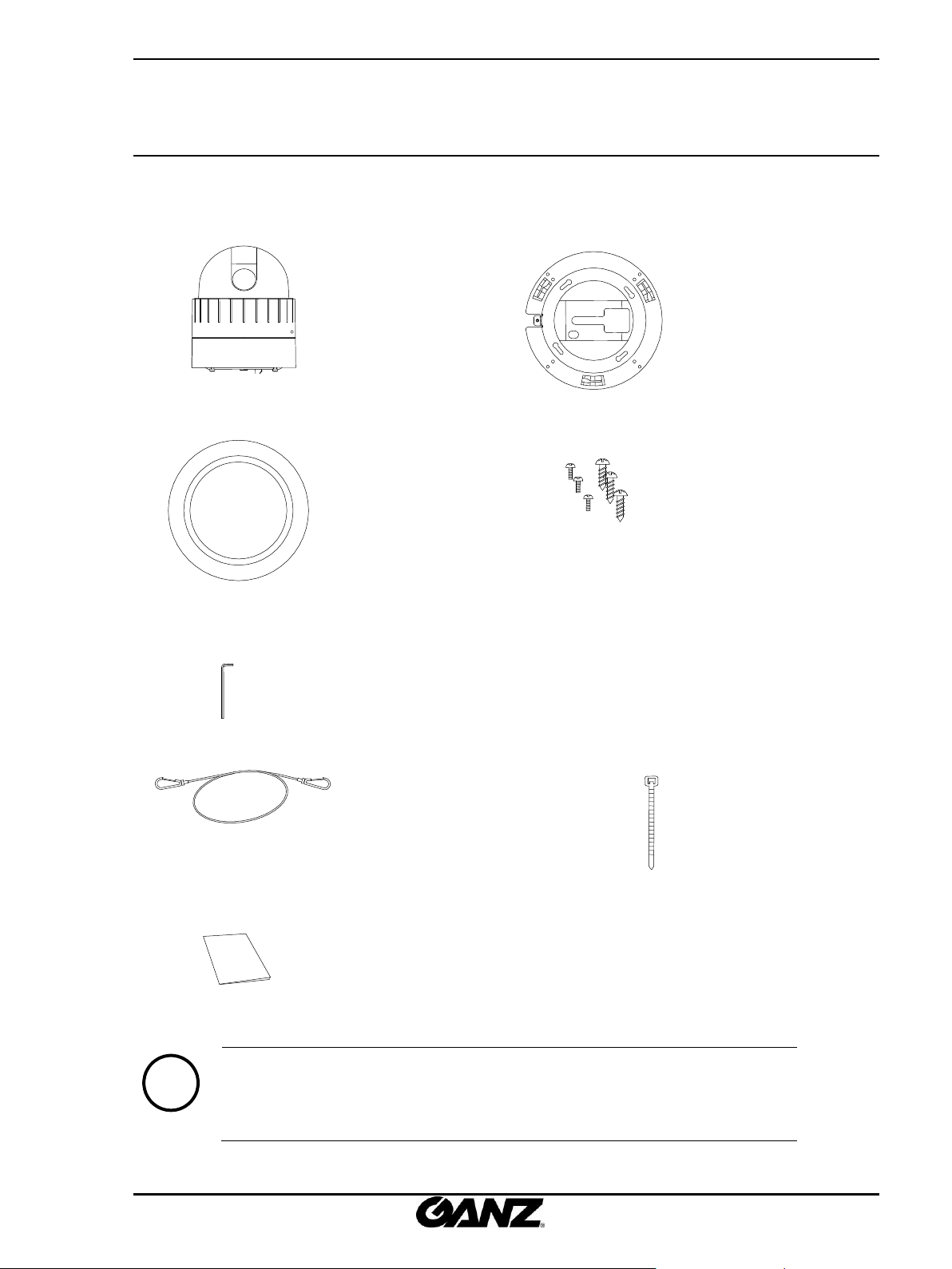
Camera
Ceiling Mount Bracket
Ceiling Cover
Screws
Wrench
Terminal block
(2Pin, 3Pin , 5Pin ,6Pin)
Safety Wire
Cable Ties
Quick Installation Guide
Note
i
The above contents are subject to change without prior notice.
2. PACKAGE CONTENTS
Unpack carefully and handle the equipment with care. The packaging contains:
06A.02 7
ZN-PTZ(W)xxVPIPE4100/IPE4500 Installation Guide
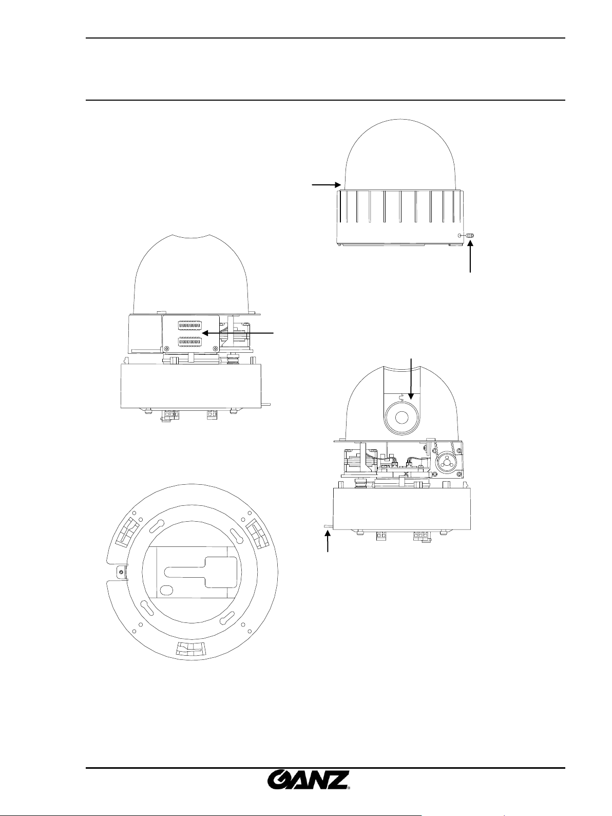
Lock Screw
Bubble
Lock Holder
Dip Switch
Camera Lens
Ceiling Mount Bracket for indoor
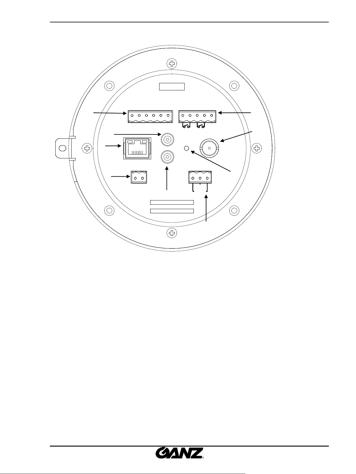
3. PART NAMES
06A.02 8
ZN-PTZ(W)xxVPIPE4100/IPE4500 Installation Guide
ALARM AUX
GND 1 2
1 2
D+
3 4 GND
D- GND
AC24VRS 485
GND
ON
VIDEO
OUT
LINE OUT
MIC/
100 BaseT
LINE IN
①
②
③
④
⑤
⑥
⑧
⑨
⑦
* Models herein and their appearance
are subject to change without any prior
notice.
06A.02 9

ZN-PTZ(W)xxVPIPE4100/IPE4500 Installation Guide
LED1 LED2
① LAN Connector (Ethernet)
This is a RJ45 LAN connector for 10/100 Base-T Ethernet.
This LED lights up as orange and turns green when the encoder is powered on.
LED operation setting:
For the factory default setting, LED 2 blinks for the heartbeat and LED 1 turns on for video signal. To
change its setting, refer to the section 4.5.11. LED Setting of the NVC Web Page User’s Manual.
② RS-485
The camera supports RS-485 Serial Communication Port.
③ 3 pin connector for power
The camera needs an AC24V for power supply. Refer to the section “5.1.Connectors” for more specific
information.
④ External video
It is an analog video output port.
⑤ 5 pin connector for D/O
The camera provides 2 channel D/O. Refer to the section “5.1.Connectors” for more specific
information.
⑥ 6 pin connector for D/I
The camera provides 4 channel D/I. Refer to the section “5.1.Connectors” for more specific information.
⑦ Audio Output
The camera has a mono audio output.
⑧ Audio Input
The camera has a mono audio input.
⑨ Reset
Reset switch is used for restarting or resetting the camera as Factory Default (FD). Refer to the section
“6.3. Reset” for more specific information.
06A.02 10
ZN-PTZ(W)xxVPIPE4100/IPE4500 Installation Guide
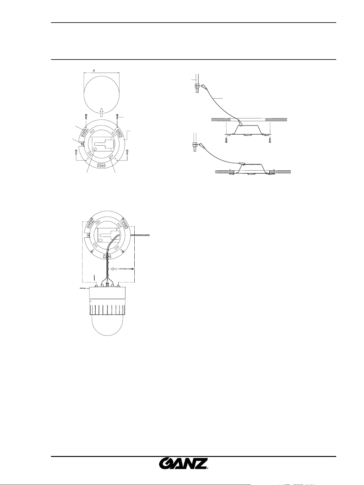
Before you install the camera, you should set
the DIP switches to configure the camera ID,
communication protocol. Please refer to the
page15. DIP Switch
1. Find the places which are strong enough to
support the camera, about 2kg.
2. Make a hole, Ø 147mm, on the ceiling.
3. Hook the safety wire to suspension and the
safety wire hold on the bracket.
4. Install the ceiling mount bracket by driving 4
screws, Ø 4mm tapping screws.
5. You can make wires simple by cable ties.
SAFETY WIRE
CABLE TIE
LOCK HOLDER 2
MOUNT HOLDER
147.0 mm
COVER HOLE
LOCK HOLDER 1
SAFETY WIRE HOLE
MOUNTING HOLE
CELING BRACKET
SCREW(Ø4.0)
A
B
C
4. INSTALLATION
06A.02 11
 Loading...