

Ganz ZN-PTZ202XE User Manual
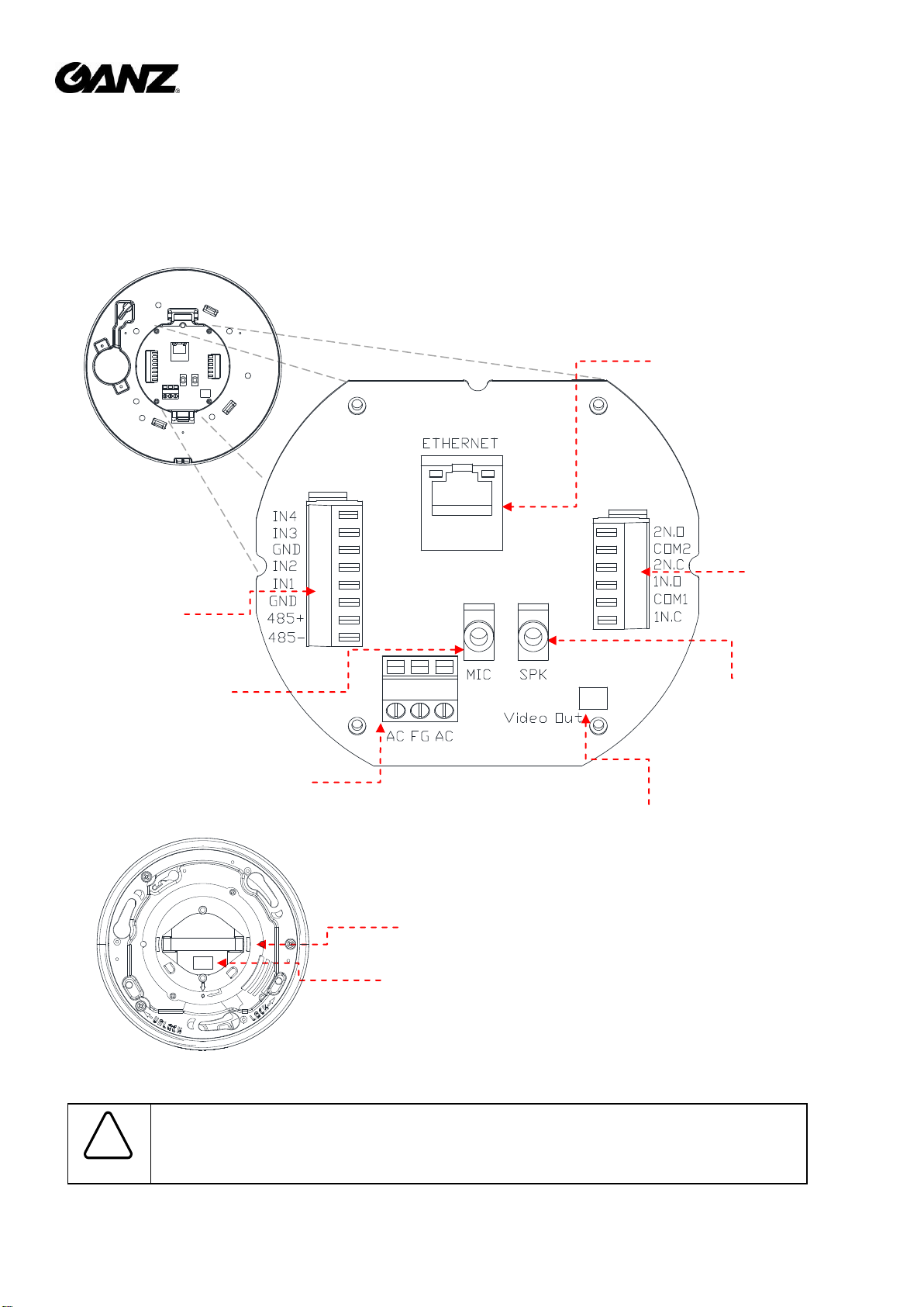
Incorrect connection may cause malfunction or damage to the IP device.
Caution
!
* Model design and appearance are subject to change without any prior notice
6-pin
Terminal
Connect
(Digital Out)
3.5 mm Microphone
Stereo Jack
3.5 mm Speaker
Stereo Jack
Video Out
32-pin socket
microSD slot
PCB Top View
Main Camera Body Top View
LAN Cable
3-pin Power
Terminal Connect
③
8-pin
Terminal
Connect
(Digital In)
ZN-PTZ202XE Quick Installation Guide
This manual provides instructions for quick installation and basic configuration of your IP device.
Step1. Connect cables to IP device
Connect required cables to the device including the power cable and LAN cable. To see the correct positions
of all connectors, refer to the following image below.
XC4202 Ver1.1
1
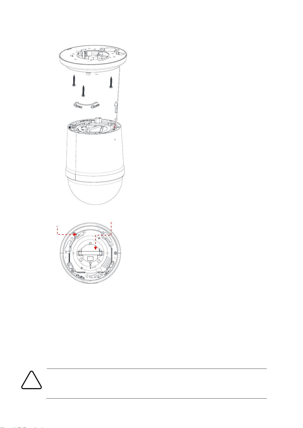
1) Secure three screws inside a PCB board shield’s
three unit holders with metal rings attached in the
end.
2) Connect all necessary cables to a PCB board
before attaching the shield to an installation spot.
3) Under the PCB board shield has a 32-pin
connector which matches the main camera body’s
32-pin socket; The shield’s three unit holders also
align with the main camera body’s three unit
holder holes.
4) Once cable connect is complete along with
brackets and poles on an installation spot,
hook the roll-up string that is attached to a
board shield to the main body. Main body has
a secured string holder hole.
5) Align the connector and socket, and then push
the main body to conjoin.
6) Once two units are attached, rotate the main
camera body counterclockwise to secure the lock.
Caution
!
To prevent products from damaging, place the camera on stable and non-vibrating surfaces. If
the stability is in doubt, consult with safety personnel for reinforcements, and then proceed
with the installation.
Roll-up
String hole
32-pin socket
Step2. Install IP device
XC4202 Ver1.1
2
Convert the last two set of hexadecimal numbers to decimal numbers.
Step3. Set the lens position
The device is 360° rotating camera and fully controlled by web user interface.
Once the unit’s installation is complete and connected properly, please refer to ZN-XE Series Web User’s
Manual for the device’s PAN/TILT configuration instructions.
Step4. Set up network environment
The default IP address of the device is 192.168.XXX.XXX. Users can identify the IP address of the device from
converting the MAC address’s hexadecimal numbers, which is attached to the device. Be sure that the device
and PC are on a same area network before running the installation.
Generic IP Environment
In case of generic private network environment where IP address 192.168.XXX.XXX are used, users may view
the live streaming images on a web page using the device’s default IP address:
1. Convert the device’s MAC address to the IP address. Refer to the Hexadecimal-Decimal Conversion Chart
at the end of the manual.
(The MAC address of the device is attached on the side or bottom of the device.)
2. Start the Microsoft® Internet Explorer web browser and enter the IP address of the device.
3. Web streaming and device configurations are supported through ActiveX program. When the ActiveX
installation pop-up window appears, authorize and install the ActiveX setup.exe,
XC4202 Ver1.1
3
 Loading...